EP0033096B1 - Membranpumpe - Google Patents
Membranpumpe Download PDFInfo
- Publication number
- EP0033096B1 EP0033096B1 EP81100270A EP81100270A EP0033096B1 EP 0033096 B1 EP0033096 B1 EP 0033096B1 EP 81100270 A EP81100270 A EP 81100270A EP 81100270 A EP81100270 A EP 81100270A EP 0033096 B1 EP0033096 B1 EP 0033096B1
- Authority
- EP
- European Patent Office
- Prior art keywords
- diaphragm
- stem
- plate
- housing
- motor
- Prior art date
- Legal status (The legal status is an assumption and is not a legal conclusion. Google has not performed a legal analysis and makes no representation as to the accuracy of the status listed.)
- Expired
Links
Images
Classifications
-
- F—MECHANICAL ENGINEERING; LIGHTING; HEATING; WEAPONS; BLASTING
- F04—POSITIVE - DISPLACEMENT MACHINES FOR LIQUIDS; PUMPS FOR LIQUIDS OR ELASTIC FLUIDS
- F04B—POSITIVE-DISPLACEMENT MACHINES FOR LIQUIDS; PUMPS
- F04B43/00—Machines, pumps, or pumping installations having flexible working members
- F04B43/0009—Special features
- F04B43/0054—Special features particularities of the flexible members
-
- F—MECHANICAL ENGINEERING; LIGHTING; HEATING; WEAPONS; BLASTING
- F04—POSITIVE - DISPLACEMENT MACHINES FOR LIQUIDS; PUMPS FOR LIQUIDS OR ELASTIC FLUIDS
- F04B—POSITIVE-DISPLACEMENT MACHINES FOR LIQUIDS; PUMPS
- F04B43/00—Machines, pumps, or pumping installations having flexible working members
- F04B43/02—Machines, pumps, or pumping installations having flexible working members having plate-like flexible members, e.g. diaphragms
- F04B43/06—Pumps having fluid drive
-
- F—MECHANICAL ENGINEERING; LIGHTING; HEATING; WEAPONS; BLASTING
- F16—ENGINEERING ELEMENTS AND UNITS; GENERAL MEASURES FOR PRODUCING AND MAINTAINING EFFECTIVE FUNCTIONING OF MACHINES OR INSTALLATIONS; THERMAL INSULATION IN GENERAL
- F16J—PISTONS; CYLINDERS; SEALINGS
- F16J3/00—Diaphragms; Bellows; Bellows pistons
- F16J3/02—Diaphragms
Definitions
- the invention relates to a diaphragm pump operated by fluid under pressure comprising a diaphragm assembly dividing a housing into pumping and propellant chambers, and including a rigid motor stem extending from the diaphragm rear side to a spring motor and a molded relatively flexible elastomeric diaphragm having an imperforate monolithic front layer secured to the stem and covering the entirety of the front side.
- a diaphragm pump is known in accordance with the prior art portion of claim 1 (US-A-2,675,758) in which the head of the stem is molded into a thickened central portion of the elastomeric diaphragm. Due to the non-rigid connection of the flexible diaphragm to the motor stem the response time is necessarily long and this connection will be destroyed by a rapid movement of the diaphragm.
- a diaphragm pump comprising a housing which includes a stem guide extending from the rear side of the housing and including a bore for slidably receiving the elongate rigid motor stem and a seal disposed on said motor stem is known from US-A-3,672,791.
- a diaphragm pump wherein the spring motor includes a coil spring disposed concentrically around the elongate rigid motor stem outboard of the housing and a spring retainer on an outboard end of said stem and having a cup shaped opening for receiving one end of the coil spring therein is known from US-A-3,299,826.
- the invention as claimed in claim 1 solves the problem of how to design a diaphragm pump having a fast response time.
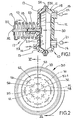
- the pump 10 is a pneumatically powerable single action device having a two-piece housing 11, coupled together by a V-clamp-ring 54, and a diaphragm assembly 30 which divides the interior of the housing 11 into a pumping chamber 12 and a propellant chamber 13.
- the pumping chamber 12 has a fluid inlet 14 with an inlet check valve 21 and a fluid outlet 15 with an outlet check valve 22.
- Fluid outlet 15 is disposed at the highest possible point in housing 11, as viewed in Figure 1, to preclude the entrapment of air in chamber 12 above outlet 15. With such a location of outlet 15 pump 10 will operate in either the horizontal position of Figure 1, or a vertical position without entrapping and pumping air from chamber 12. Housing 11 also has a circumferential groove 11 B adjacent inlet 14 and outlet 15 to preclude any possibility of diaphragm assembly 30 from sealing off said inlet or outlet.
- the propellant chamber 13 has a fluid port 16 through which pressurized propellant fluid, for example compressed carbon dioxide gas, may be admitted or released.
- the diaphragm assembly 30 includes a reinforcing plate 31, a motor stem 32 and the diaphragm 33.
- the plate 31 is substantially planar or flat, is relatively rigid under the forces it is subjected to, and is preferably made of metal.
- the plate 31 has a front side 34 facing towards the pumping chamber 12, and a rear side 35 facing towards the propellant chamber 13.
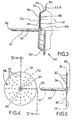
- a central aperture 36 is in the middle of the plate 31, and perforations 37 in the form of round holes through the plate 31 are in a pattern 38 around and generally concentric to the aperture 36.
- the motor stem 32 is an elongate member, preferably of metal, and is mounted to the plate 31.
- An elongate body 40 of the stem 32 is passed through the aperture 36 and a diametrically enlarged head 42 abuttingly engages against the plate front side 34.
- the elongate stem axis 41 is substantially perpendicular to the plane of the plate 31.
- the stem 32 projects from the plate rear side 35, through the propellant chamber 13, and through a bore 23 defined by a stem guide 11 A in the rear side of the housing 11.
- the stem 32 is reciprocable in the bore 23 and a seal 43 fluid tightly seals the stem 32 to the bore 23.
- seal 43 is advantageous to place seal 43 on stem 32 rather than in the stem guide 11 A because it is easier to repair and assemble. Seal 43 may be replaced merely by removing stem 32 and the diaphragm assembly 30 from the pump with the construction of the present invention. In addition, if seal 43 were placed within the stem guide 11A a retaining clip would be needed to hold it in place.
- Stem guide 11 A and housing 11 are fabricated from a thermoplastic polyester of low friction material to permit the reciprocation of stem 32 and seal 43 therein.
- An example of a suitable material is, ValoxO, manufactured by the General Electric Company.
- a spring motor 17 biases the motor stem 32, plate 31, and most of the diaphragm 33 towards the rear of the housing 11 and towards the propellant chamber 13.
- the spring motor 17 has a spring 18 compressed between the housing 11 and a spring retainer 19 held on and to the motor stem 32 by a keeper 20 in the stem.
- Retainer 19 in conjunction with spring 18 has a self-centering action on stem 32. That is, it tends to direct stem 32 along the central axis of bore 23 in stem guide 11 A.
- the diaphragm 33 is continuous, specifically it is of integral one-piece construction and has a front layer 51 on the plate front side 34, a rear layer 52 on the plate rear side 35 and a resiliently flexible annular bellows 53 around and to the outside of the plate 31 and the front and rear layers 51, 52.
- an annular V-clamp ring 54 which clamps a bead 53A of bellows 53 in a fluid tight manner between the two respective pieces of the housing.
- the front layer 51 is imperforate and generally monolithic and completely covers the plate 31 and stem 32 from the pumping chamber 12.
- the front layer 51 has a convex section 55 projecting into the pumping chamber 12 and imperforately covering the stem enlarged head 42.
- the covered stem 32 may be welded to the plate 31 and this type of construction is particularly useful if the diaphragm assembly 30 is to be driven by a mechanical or electrical device such as a cam, lever or solenoid (not shown) operatively engaging the motor stem 32 and pushing it inwardly. In the illustrated pneumatically powerable mode, the stem 32 need not be welded to plate 31.
- the rear layer 52 is abutted against and secured to the stem 40 immediately adjacent the aperture 36.
- Enlarged head 42 is both mechanically abraded and adhesively secured to diaphragm convex section 55 thus forming a fluid tight seal. This precludes propellant gas from bleeding through diaphragm 33 in the region of head 42 and convex section 55.
- the diaphragm 33 is also both mechanically and adhesively secured to the plate 31 and stem 32.
- the plate 31 is mechanically abraded on both of the front and rear sides 34, 35 and covered with a thin layer of adhesive (not shown).
- the elastomeric diaphragm 33 is molded in-situ about the stem 32 and plate 31 and integral elastomeric pins 58 are molded through the perforations 37. These pins 58 are integral with both the front layer 51 and the rear layer 52 and mechanically retain the layers 51, 52 against the plate 31.
- the rear layer 52 has a plurality of perforations 56 which open to the propellant chamber. These perforations 56 enable mechanical support of the plate 31 during molding of the diaphragm 33.
- the perforations 37 and the pins 58 therein are laterally spaced from any of the perforations 56 so that every diaphragm pin 58 is adjoined to both the front and rear layers 51, 52 and neither of the diaphragm layers can be pulled from the plate 31 without putting all adjacent pins 58 under tensile stress.
- the layers 51, 52 and plate 31 are intended to be substantially perpendicular to the motor stem 32, and are held off but closely spaced from the housing 11 by concentric C-shaped arcuate ribs 25 standing off the inside of the housing 11 in the propellant chamber and between the housing 11 and the rear side 35.
- the ribs 25 support the plate 31 and diaphragm layers 51, 52 in a position perpendicular to the stem 32 in the position illustrated in Figure 1.
- the propellant fluid port 16 is radially within the opening between ends of the C-shaped ribs 25.
- the space behind diaphragm 33 at the beginning of a pumping stroke is kept to a minimum, namely it is defined by the height of ribs 25.
- This small space provides definite advantages. For example, it shortens the response time of the pump to incoming propellant pressure and it maximizes the volume of fluid pumped per stroke for a housing of a given size.
- the ribs 25 evenly distribute the propellant behind diaphragm 33 further shortening the response time of the pump to the driving force of the propellant.
- the diaphragm assembly 30 has been fabricated as an assembly of the plate 31, stem 32 and diaphragm 33 and it is one component, and cannot be broken down or taken apart.
- the diaphragm assembly 30 is placed in the housing 11, the spring motor 17 is operatively connected, and the diaphragm V-clamp ring 54 secures the two pieces of housing 11 together in a fluid tight manner.
- the fluid inlet 14 is fluidly connected to a source of fluid intended to be pumped, the fluid outlet 15 is connected to a destination to which fluid from the source is to be pumped, and the fluid port 16 is connected to a source of pressurized propellant fluid, preferably but not necessarily a gas, under the control of suitable valving for intermittent application and relief of propellant pressure.
- a source of pressurized propellant fluid preferably but not necessarily a gas
- the diaphragm assembly 30 When the pump 10 is on standby and awaiting use, the diaphragm assembly 30 is in the position and configuration shown best in Figure 1.
- the spring motor 17 exerts a constant bias on the diaphragm assembly 30 and keeps the layers 51, 52 and plate 31 against the ribs 25 and perpendicular to the stem 32. As stated hereinbefore, this minimizes the volume of the propellant chamber 13 and maximizes the volume of the pumping chamber 12.
- the enlarged head 42 is positively abutted against the plate 31 and cannot come apart. There is no metal exposed to fluid in the pumping chamber 12.
- Propellant pressure is selectively applied through the port 16 and is evenly and rapidly distributed in the propellant chamber 13 by ribs 25 behind diaphragm 33.
- the pumping chamber 12 is reduced in volume and the inlet check valve 21 closes and the outlet check valve 22 opens and fluid is pumped out of the fluid outlet 15.
- the propellant pressure is applied equally on the rear layer 52 and bellows 53. Under this pressure the rear layer 52 retains the bellows 53 and the plate 31.
- the propellant force is taken by the plate 31, transferred through the head 42 to the stem 32 which is then drawn into the housing 11 as the spring motor 17 is compressed during pumping.
- the spring motor 17 begins to pull the diaphragm assembly 30 back.
- the outlet check valve 22 closes and the inlet check valve 21 opens and new fluid is drawn from the source and into the pump chamber 12. This new fluid is drawn by suction and the diaphragm 33 and plate 31 will be negatively pressurized.
- the spring motor 17 pushes the motor stem 32 outward, the stem head 42 pulls the plate 31, and the plate pulls the front layer 51 and pushes the rear layer 52.
- the front and rear layers 51, 52 both pull the bellows 53.
- the front layer 51 cannot separate from the plate 31 under vacuum because of the bonding and the pins 58 which tie the front and rear layers 51, 52 together and to the plate 31.
- the pump 10 and diaphragm assembly 30 offer substantial advantages in the handling of food fluids or corrosives. There is no metal to fluid contact, no possibility of failure between the plate 31 and the stem 32, and the diaphragm 33 is virtually inseparable from the plate 31 and stem 32. There are no crevices for contamination and cleanability is enhanced.
- the problem of the diaphragm bellows being blown over the front side of the rigid plate has been solved without the necessity for a rigid block or other device on the front side of the diaphragm.
- the pump 10 is able to be pressurized at 345 kPa without the erratic collapse of diaphragm and short delivery of pumped fluid.
- a very high strength spring motor may be used with this improved diaphragm and pump and the suction capabilities are sufficient for lifting beverage syrup concentrates at least 6.1 meters.
Landscapes
- Engineering & Computer Science (AREA)
- General Engineering & Computer Science (AREA)
- Mechanical Engineering (AREA)
- Reciprocating Pumps (AREA)
Claims (4)
Priority Applications (1)
| Application Number | Priority Date | Filing Date | Title |
|---|---|---|---|
| AT81100270T ATE10669T1 (de) | 1980-01-29 | 1981-01-15 | Membranpumpe. |
Applications Claiming Priority (2)
| Application Number | Priority Date | Filing Date | Title |
|---|---|---|---|
| US06/116,505 US4334838A (en) | 1980-01-29 | 1980-01-29 | Diaphragm type fluid pump having a flexible diaphragm with an internal reinforcing plate |
| US116505 | 1980-01-29 |
Publications (3)
| Publication Number | Publication Date |
|---|---|
| EP0033096A2 EP0033096A2 (de) | 1981-08-05 |
| EP0033096A3 EP0033096A3 (en) | 1981-08-19 |
| EP0033096B1 true EP0033096B1 (de) | 1984-12-05 |
Family
ID=22367571
Family Applications (1)
| Application Number | Title | Priority Date | Filing Date |
|---|---|---|---|
| EP81100270A Expired EP0033096B1 (de) | 1980-01-29 | 1981-01-15 | Membranpumpe |
Country Status (12)
| Country | Link |
|---|---|
| US (1) | US4334838A (de) |
| EP (1) | EP0033096B1 (de) |
| JP (1) | JPS56113082A (de) |
| AR (1) | AR224921A1 (de) |
| AT (1) | ATE10669T1 (de) |
| AU (1) | AU543721B2 (de) |
| BR (1) | BR8100432A (de) |
| DE (1) | DE3167518D1 (de) |
| ES (1) | ES8204809A1 (de) |
| MX (1) | MX152769A (de) |
| NZ (1) | NZ196141A (de) |
| SU (1) | SU1355135A3 (de) |
Cited By (8)
| Publication number | Priority date | Publication date | Assignee | Title |
|---|---|---|---|---|
| US6769231B2 (en) | 2001-07-19 | 2004-08-03 | Baxter International, Inc. | Apparatus, method and flexible bag for use in manufacturing |
| US8066671B2 (en) | 2002-05-24 | 2011-11-29 | Baxter International Inc. | Automated dialysis system including a piston and stepper motor |
| US8070709B2 (en) | 2003-10-28 | 2011-12-06 | Baxter International Inc. | Peritoneal dialysis machine |
| US8172789B2 (en) | 2000-02-10 | 2012-05-08 | Baxter International Inc. | Peritoneal dialysis system having cassette-based-pressure-controlled pumping |
| US8206338B2 (en) | 2002-12-31 | 2012-06-26 | Baxter International Inc. | Pumping systems for cassette-based dialysis |
| US8992462B2 (en) | 2002-07-19 | 2015-03-31 | Baxter International Inc. | Systems and methods for performing peritoneal dialysis |
| US9514283B2 (en) | 2008-07-09 | 2016-12-06 | Baxter International Inc. | Dialysis system having inventory management including online dextrose mixing |
| US9582645B2 (en) | 2008-07-09 | 2017-02-28 | Baxter International Inc. | Networked dialysis system |
Families Citing this family (36)
| Publication number | Priority date | Publication date | Assignee | Title |
|---|---|---|---|---|
| US4466339A (en) * | 1981-07-23 | 1984-08-21 | William R. Selwood Limited | Diaphragm assembly |
| US4567814A (en) * | 1983-11-04 | 1986-02-04 | Jodel Associates, Inc. | Interchangeable connector and diaphragm assembly |
| US4681518A (en) * | 1985-02-19 | 1987-07-21 | The Coca-Cola Company | Single-acting, gas operated pump |
| IL77935A (en) * | 1986-02-19 | 1990-04-29 | Tmb Fertilizer Pumps | Liquid driven reciprocating pump |
| US5006104A (en) * | 1988-11-07 | 1991-04-09 | The Cleveland Clinic Foundation | Heart pump having contractible guide mechanism for pusher plate |
| DE3931516C2 (de) * | 1989-09-21 | 1993-10-14 | Ott Kg Lewa | Membranpumpe mit mechanisch angetriebener Membran |
| US5186615A (en) * | 1990-06-26 | 1993-02-16 | Karldom Corporation | Diaphragm pump |
| US5438510A (en) * | 1993-03-03 | 1995-08-01 | Deka Products Limited Partnership | User interface and monitoring functions for automated peritoneal dialysis systems |
| US5431626A (en) * | 1993-03-03 | 1995-07-11 | Deka Products Limited Partnership | Liquid pumping mechanisms for peritoneal dialysis systems employing fluid pressure |
| US5350357A (en) * | 1993-03-03 | 1994-09-27 | Deka Products Limited Partnership | Peritoneal dialysis systems employing a liquid distribution and pumping cassette that emulates gravity flow |
| US5540568A (en) * | 1993-07-26 | 1996-07-30 | National Instrument Co., Inc. | Disposable rolling diaphragm filling unit |
| US5634391A (en) * | 1996-07-09 | 1997-06-03 | Westinghouse Air Brake Co. | Inert plastic coated flexible type diaphragm for application in a sanitary type pump |
| US5687633A (en) * | 1996-07-09 | 1997-11-18 | Westinghouse Air Brake Company | Insert type member for use in a flexible type pump diaphragm |
| US5765466A (en) * | 1997-01-24 | 1998-06-16 | Indian Head Industries | Brake actuator with self-centering diaphram |
| US6230609B1 (en) * | 1999-06-03 | 2001-05-15 | Norton Performance Plastics Corporation | Fluoropolymer diaphragm with integral attachment device |
| US6905314B2 (en) | 2001-10-16 | 2005-06-14 | Baxter International Inc. | Pump having flexible liner and compounding apparatus having such a pump |
| US6814547B2 (en) | 2002-05-24 | 2004-11-09 | Baxter International Inc. | Medical fluid pump |
| US7175606B2 (en) | 2002-05-24 | 2007-02-13 | Baxter International Inc. | Disposable medical fluid unit having rigid frame |
| US7007824B2 (en) | 2003-01-24 | 2006-03-07 | Baxter International Inc. | Liquid dispenser and flexible bag therefor |
| AU2004252114B2 (en) * | 2003-06-09 | 2010-09-09 | Dako Denmark A/S | Diaphram metering chamber dispensing systems |
| JP4226427B2 (ja) * | 2003-09-29 | 2009-02-18 | 京三電機株式会社 | ダイヤフラムポンプ装置 |
| DE102005010291A1 (de) * | 2005-03-02 | 2006-09-07 | Ami-Agrolinz Melamine International Gmbh | Membranpumpe und ein Verfahren zur Herstellung einer Pumpenmembran |
| JP5274172B2 (ja) * | 2008-09-17 | 2013-08-28 | 株式会社日立産機システム | インクジェット記録装置 |
| US10626939B2 (en) * | 2010-07-07 | 2020-04-21 | Haldex Brake Products Corporation | Adhesive attachment of the disc brake pushrod plate to the diaphragm |
| US8715238B2 (en) * | 2010-07-23 | 2014-05-06 | Medela Holding Ag | Pumping device, as for enteral feeding assembly |
| CN103133301B (zh) * | 2013-03-06 | 2015-12-09 | 肖立峰 | 高压隔膜泵的耐高压复合式隔膜 |
| US10267303B2 (en) * | 2013-08-30 | 2019-04-23 | Flow Control Llc. | High viscosity portion pump |
| US10697447B2 (en) * | 2014-08-21 | 2020-06-30 | Fenwal, Inc. | Magnet-based systems and methods for transferring fluid |
| JP7039477B2 (ja) * | 2015-11-10 | 2022-03-22 | レプリゲン・コーポレイション | 交互接線流の使い捨て濾過ユニット |
| US10422331B2 (en) | 2016-08-12 | 2019-09-24 | Ingersoll-Rand Company | One piece diaphragm |
| US11179516B2 (en) | 2017-06-22 | 2021-11-23 | Baxter International Inc. | Systems and methods for incorporating patient pressure into medical fluid delivery |
| CN109578287B (zh) * | 2019-01-25 | 2020-08-07 | 卡川尔流体科技(上海)有限公司 | 一种输送泵 |
| US11209058B2 (en) | 2019-11-19 | 2021-12-28 | Tse Brakes, Inc. | Spring brake actuator |
| US12455026B2 (en) | 2020-11-30 | 2025-10-28 | Graco Minnesota Inc. | Sanitary clamp for diaphragm pump covers |
| US11906007B2 (en) * | 2021-07-27 | 2024-02-20 | Hyundai Motor Company | S-cam brake |
| WO2024039879A1 (en) * | 2022-08-19 | 2024-02-22 | Applied Materials, Inc. | Liquid metal metering valves |
Family Cites Families (20)
| Publication number | Priority date | Publication date | Assignee | Title |
|---|---|---|---|---|
| FR513215A (fr) * | 1919-10-08 | 1921-02-10 | Charles Scotte | Système de diaphragme étanche pour pompes |
| FR46022E (fr) * | 1934-10-17 | 1936-02-15 | Perfectionnement aux compresseurs ou pompes à membrane | |
| US2675758A (en) * | 1949-01-06 | 1954-04-20 | Infilco Inc | Chemical feeder |
| US2711134A (en) * | 1950-07-26 | 1955-06-21 | Infilco Inc | Chemical feeder |
| US2724410A (en) * | 1950-12-29 | 1955-11-22 | Bendix Westinghouse Automotive | Fluid pressure diaphragm securing assembly |
| US2690859A (en) * | 1951-11-21 | 1954-10-05 | Snyder Jacob Rush | Dispensing apparatus for multiple fluids |
| US2741187A (en) * | 1952-05-31 | 1956-04-10 | Clifford B Moller | Pump head mounting |
| US2869585A (en) * | 1954-02-15 | 1959-01-20 | Gen Motors Corp | Flexible diaphragm |
| FR1136478A (fr) * | 1954-10-11 | 1957-05-23 | Girdlestone Pumps Ltd | Perfectionnements aux diaphragmes de pompes |
| US3000320A (en) * | 1957-07-18 | 1961-09-19 | Ring Sandiford | Pump |
| US3299826A (en) * | 1965-06-28 | 1967-01-24 | Pacific Lighting Gas Supply Co | Diaphragm pump |
| US3386345A (en) * | 1966-08-01 | 1968-06-04 | John F. Taplin | Rolling diaphragm device having centering button on diaphragm and having piston rod rotatable relative to piston |
| US3672791A (en) * | 1970-07-17 | 1972-06-27 | Ladish Co | Pumping system with controlled liquid addition |
| FR2255586A1 (en) * | 1973-12-21 | 1975-07-18 | Poudres & Explosifs Ste Nale | Dosing pump for dispensing viscous (explosive) materials - using a flexible elastic membrane pressure driven |
| US4022114A (en) * | 1974-07-05 | 1977-05-10 | Refrigerating Specialties Company | Flexible diaphragm construction |
| US4086036A (en) * | 1976-05-17 | 1978-04-25 | Cole-Parmer Instrument Company | Diaphragm pump |
| CA1077406A (en) * | 1976-07-16 | 1980-05-13 | Paul A. S. Charles | Filtering elements |
| DE2649989C3 (de) * | 1976-10-30 | 1981-07-02 | Daimler-Benz Ag, 7000 Stuttgart | Stellantrieb |
| DE2815212A1 (de) * | 1978-04-08 | 1979-10-11 | Brumme Kg Effbe Werk | Membrananordnung mit einer bewegungsmembran |
| US4231721A (en) * | 1978-10-12 | 1980-11-04 | General Motors Corporation | Diaphragm pump |
-
1980
- 1980-01-29 US US06/116,505 patent/US4334838A/en not_active Expired - Lifetime
-
1981
- 1981-01-06 AU AU66026/81A patent/AU543721B2/en not_active Ceased
- 1981-01-15 AT AT81100270T patent/ATE10669T1/de not_active IP Right Cessation
- 1981-01-15 EP EP81100270A patent/EP0033096B1/de not_active Expired
- 1981-01-15 DE DE8181100270T patent/DE3167518D1/de not_active Expired
- 1981-01-23 MX MX185678A patent/MX152769A/es unknown
- 1981-01-26 JP JP911781A patent/JPS56113082A/ja active Granted
- 1981-01-27 BR BR8100432A patent/BR8100432A/pt unknown
- 1981-01-28 NZ NZ196141A patent/NZ196141A/en unknown
- 1981-01-28 SU SU813235304A patent/SU1355135A3/ru active
- 1981-01-28 AR AR284094A patent/AR224921A1/es active
- 1981-01-28 ES ES498887A patent/ES8204809A1/es not_active Expired
Cited By (22)
| Publication number | Priority date | Publication date | Assignee | Title |
|---|---|---|---|---|
| US8206339B2 (en) | 2000-02-10 | 2012-06-26 | Baxter International Inc. | System for monitoring and controlling peritoneal dialysis |
| US9474842B2 (en) | 2000-02-10 | 2016-10-25 | Baxter International Inc. | Method and apparatus for monitoring and controlling peritoneal dialysis therapy |
| US8323231B2 (en) | 2000-02-10 | 2012-12-04 | Baxter International, Inc. | Method and apparatus for monitoring and controlling peritoneal dialysis therapy |
| US8172789B2 (en) | 2000-02-10 | 2012-05-08 | Baxter International Inc. | Peritoneal dialysis system having cassette-based-pressure-controlled pumping |
| US6769231B2 (en) | 2001-07-19 | 2004-08-03 | Baxter International, Inc. | Apparatus, method and flexible bag for use in manufacturing |
| US8529496B2 (en) | 2002-05-24 | 2013-09-10 | Baxter International Inc. | Peritoneal dialysis machine touch screen user interface |
| US8684971B2 (en) | 2002-05-24 | 2014-04-01 | Baxter International Inc. | Automated dialysis system using piston and negative pressure |
| US8075526B2 (en) | 2002-05-24 | 2011-12-13 | Baxter International Inc. | Automated dialysis system including a piston and vacuum source |
| US8376999B2 (en) | 2002-05-24 | 2013-02-19 | Baxter International Inc. | Automated dialysis system including touch screen controlled mechanically and pneumatically actuated pumping |
| US8506522B2 (en) | 2002-05-24 | 2013-08-13 | Baxter International Inc. | Peritoneal dialysis machine touch screen user interface |
| US9511180B2 (en) | 2002-05-24 | 2016-12-06 | Baxter International Inc. | Stepper motor driven peritoneal dialysis machine |
| US8066671B2 (en) | 2002-05-24 | 2011-11-29 | Baxter International Inc. | Automated dialysis system including a piston and stepper motor |
| US8740837B2 (en) | 2002-07-19 | 2014-06-03 | Baxter International Inc. | Pumping systems for cassette-based dialysis |
| US8740836B2 (en) | 2002-07-19 | 2014-06-03 | Baxter International Inc. | Pumping systems for cassette-based dialysis |
| US8992462B2 (en) | 2002-07-19 | 2015-03-31 | Baxter International Inc. | Systems and methods for performing peritoneal dialysis |
| US9283312B2 (en) | 2002-07-19 | 2016-03-15 | Baxter International Inc. | Dialysis system and method for cassette-based pumping and valving |
| US8679054B2 (en) | 2002-07-19 | 2014-03-25 | Baxter International Inc. | Pumping systems for cassette-based dialysis |
| US8206338B2 (en) | 2002-12-31 | 2012-06-26 | Baxter International Inc. | Pumping systems for cassette-based dialysis |
| US8900174B2 (en) | 2003-10-28 | 2014-12-02 | Baxter International Inc. | Peritoneal dialysis machine |
| US8070709B2 (en) | 2003-10-28 | 2011-12-06 | Baxter International Inc. | Peritoneal dialysis machine |
| US9514283B2 (en) | 2008-07-09 | 2016-12-06 | Baxter International Inc. | Dialysis system having inventory management including online dextrose mixing |
| US9582645B2 (en) | 2008-07-09 | 2017-02-28 | Baxter International Inc. | Networked dialysis system |
Also Published As
| Publication number | Publication date |
|---|---|
| SU1355135A3 (ru) | 1987-11-23 |
| AR224921A1 (es) | 1982-01-29 |
| US4334838A (en) | 1982-06-15 |
| NZ196141A (en) | 1984-03-16 |
| ES498887A0 (es) | 1982-05-01 |
| AU6602681A (en) | 1981-08-06 |
| BR8100432A (pt) | 1981-08-11 |
| ATE10669T1 (de) | 1984-12-15 |
| JPS56113082A (en) | 1981-09-05 |
| EP0033096A2 (de) | 1981-08-05 |
| MX152769A (es) | 1986-05-09 |
| ES8204809A1 (es) | 1982-05-01 |
| AU543721B2 (en) | 1985-05-02 |
| DE3167518D1 (en) | 1985-01-17 |
| JPH0255635B2 (de) | 1990-11-27 |
| EP0033096A3 (en) | 1981-08-19 |
Similar Documents
| Publication | Publication Date | Title |
|---|---|---|
| US4334838A (en) | Diaphragm type fluid pump having a flexible diaphragm with an internal reinforcing plate | |
| US5002471A (en) | Disposable cell and diaphragm pump for use of same | |
| EP1490598B1 (de) | Kopfdruckentlastungsanordnung | |
| US4865521A (en) | Vacuum breaking device for ejector pump | |
| US6901961B2 (en) | Double diaphragm pump having a spool valve | |
| US20040047748A1 (en) | Double diaphragm pump including spool valve air motor | |
| JPS60175800A (ja) | エゼクタポンプ | |
| WO2005024281A1 (ja) | 方向制御弁 | |
| JPS6388282A (ja) | 定量ポンプ | |
| JP2007504396A (ja) | ディーゼルエンジンのための排ガス後処理媒体、特に尿素水溶液を搬送するためのポンプ | |
| EP1730403B1 (de) | Membranpumpe | |
| US4610192A (en) | Reciprocable device | |
| US5104299A (en) | Electromagnetic reciprocating pump | |
| US4824337A (en) | Valve assembly for an oscillating pump | |
| US6776591B1 (en) | Membrane pump comprising an inlet opening that is controlled by the membrane | |
| EP1094261A2 (de) | Magnetventil | |
| US4480969A (en) | Fluid operated double acting diaphragm pump housing and method | |
| US20180313454A1 (en) | Check valve and liquid delivery pump | |
| CA1164727A (en) | Fast acting fluid pump and diaphragm assembly therefor | |
| US7367785B2 (en) | Reduced icing valves and gas-driven motor and reciprocating pump incorporating same | |
| TWI839451B (zh) | 螺線管泵 | |
| US8568112B2 (en) | Reciprocating piston pump with air valve, detent and poppets | |
| US2877715A (en) | Double-diaphragm pump | |
| US3936245A (en) | Fluid compressing apparatus | |
| US4828465A (en) | Single-acting, gas-operated pump |
Legal Events
| Date | Code | Title | Description |
|---|---|---|---|
| PUAI | Public reference made under article 153(3) epc to a published international application that has entered the european phase |
Free format text: ORIGINAL CODE: 0009012 |
|
| PUAL | Search report despatched |
Free format text: ORIGINAL CODE: 0009013 |
|
| AK | Designated contracting states |
Designated state(s): AT BE DE FR GB IT NL SE |
|
| AK | Designated contracting states |
Designated state(s): AT BE DE FR GB IT NL SE |
|
| 17P | Request for examination filed |
Effective date: 19820219 |
|
| RAP1 | Party data changed (applicant data changed or rights of an application transferred) |
Owner name: THE CORNELIUS COMPANY Owner name: THE COCA-COLA COMPANY |
|
| ITF | It: translation for a ep patent filed | ||
| GRAA | (expected) grant |
Free format text: ORIGINAL CODE: 0009210 |
|
| AK | Designated contracting states |
Designated state(s): AT BE DE FR GB IT NL SE |
|
| REF | Corresponds to: |
Ref document number: 10669 Country of ref document: AT Date of ref document: 19841215 Kind code of ref document: T |
|
| PGFP | Annual fee paid to national office [announced via postgrant information from national office to epo] |
Ref country code: FR Payment date: 19841220 Year of fee payment: 5 |
|
| BECN | Be: change of holder's name |
Effective date: 19841205 |
|
| PGFP | Annual fee paid to national office [announced via postgrant information from national office to epo] |
Ref country code: BE Payment date: 19841231 Year of fee payment: 5 |
|
| RAP2 | Party data changed (patent owner data changed or rights of a patent transferred) |
Owner name: THE CORNELIUS COMPANY Owner name: THE COCA-COLA COMPANY |
|
| REF | Corresponds to: |
Ref document number: 3167518 Country of ref document: DE Date of ref document: 19850117 |
|
| ET | Fr: translation filed | ||
| PLBE | No opposition filed within time limit |
Free format text: ORIGINAL CODE: 0009261 |
|
| STAA | Information on the status of an ep patent application or granted ep patent |
Free format text: STATUS: NO OPPOSITION FILED WITHIN TIME LIMIT |
|
| 26N | No opposition filed | ||
| PGFP | Annual fee paid to national office [announced via postgrant information from national office to epo] |
Ref country code: AT Payment date: 19870131 Year of fee payment: 7 |
|
| PG25 | Lapsed in a contracting state [announced via postgrant information from national office to epo] |
Ref country code: FR Free format text: LAPSE BECAUSE OF NON-PAYMENT OF DUE FEES Effective date: 19870930 |
|
| REG | Reference to a national code |
Ref country code: FR Ref legal event code: ST |
|
| PG25 | Lapsed in a contracting state [announced via postgrant information from national office to epo] |
Ref country code: AT Effective date: 19880115 |
|
| PG25 | Lapsed in a contracting state [announced via postgrant information from national office to epo] |
Ref country code: SE Effective date: 19880116 |
|
| BERE | Be: lapsed |
Owner name: THE CORNELIUS CY Effective date: 19880131 Owner name: THE COCA-COLA CY Effective date: 19880131 |
|
| PG25 | Lapsed in a contracting state [announced via postgrant information from national office to epo] |
Ref country code: BE Effective date: 19890131 |
|
| PGFP | Annual fee paid to national office [announced via postgrant information from national office to epo] |
Ref country code: NL Payment date: 19890131 Year of fee payment: 11 |
|
| PG25 | Lapsed in a contracting state [announced via postgrant information from national office to epo] |
Ref country code: NL Effective date: 19900801 |
|
| NLV4 | Nl: lapsed or anulled due to non-payment of the annual fee | ||
| PGFP | Annual fee paid to national office [announced via postgrant information from national office to epo] |
Ref country code: GB Payment date: 19901231 Year of fee payment: 11 |
|
| PGFP | Annual fee paid to national office [announced via postgrant information from national office to epo] |
Ref country code: DE Payment date: 19910130 Year of fee payment: 11 |
|
| ITTA | It: last paid annual fee | ||
| PG25 | Lapsed in a contracting state [announced via postgrant information from national office to epo] |
Ref country code: GB Effective date: 19920115 |
|
| GBPC | Gb: european patent ceased through non-payment of renewal fee | ||
| PG25 | Lapsed in a contracting state [announced via postgrant information from national office to epo] |
Ref country code: DE Effective date: 19921001 |
|
| EUG | Se: european patent has lapsed |
Ref document number: 81100270.8 Effective date: 19880913 |