EP0033187A2 - Elément de structure mis sous tension interne - Google Patents
Elément de structure mis sous tension interne Download PDFInfo
- Publication number
- EP0033187A2 EP0033187A2 EP81300022A EP81300022A EP0033187A2 EP 0033187 A2 EP0033187 A2 EP 0033187A2 EP 81300022 A EP81300022 A EP 81300022A EP 81300022 A EP81300022 A EP 81300022A EP 0033187 A2 EP0033187 A2 EP 0033187A2
- Authority
- EP
- European Patent Office
- Prior art keywords
- structural member
- body shell
- tensioning
- band
- anchor
- Prior art date
- Legal status (The legal status is an assumption and is not a legal conclusion. Google has not performed a legal analysis and makes no representation as to the accuracy of the status listed.)
- Ceased
Links
Images
Classifications
-
- E—FIXED CONSTRUCTIONS
- E04—BUILDING
- E04C—STRUCTURAL ELEMENTS; BUILDING MATERIALS
- E04C3/00—Structural elongated elements designed for load-supporting
- E04C3/30—Columns; Pillars; Struts
- E04C3/36—Columns; Pillars; Struts of materials not covered by groups E04C3/32 or E04C3/34; of a combination of two or more materials
-
- E—FIXED CONSTRUCTIONS
- E04—BUILDING
- E04C—STRUCTURAL ELEMENTS; BUILDING MATERIALS
- E04C3/00—Structural elongated elements designed for load-supporting
- E04C3/02—Joists; Girders, trusses, or trusslike structures, e.g. prefabricated; Lintels; Transoms; Braces
- E04C3/28—Joists; Girders, trusses, or trusslike structures, e.g. prefabricated; Lintels; Transoms; Braces of materials not covered by groups E04C3/04 - E04C3/20
Definitions
- the present Invention relates to structural members, and, more particularly, to such members that Include an outer shell of fiberglass or a similar material and to a method of assembling such members.
- Structural members such as tower legs and other columns are frequently made of steel or other metal and sometimes of wood. These conventional materials have become increasingly costly but, to date, little use has been made of alternative materials, such as fiberglass. Fiberglass has sufficient strength for many applications and has the advantage of being light In weight, which reduces shipping costs and makes the material easier to handle when a structure Is being erected. In addition, It can be fabricated In a large variety of sizes and configurations, short production runs being feasible. Moreover, the amount of fiberglass incorporated in a member and the resulting load bearing capacity can be varied considerably without changing external dimensions.
- a primary objective of the present invention is to provide an improved fiberglass structural member which overcomes the attachment difficulties previously associated with this material.
- a further objective Is to provide such a member of increased strength and rigidity.
- the present invention resides in a structural member that accomplishes the above objectives and in a method for the assembly of such a member. It includes an elongated body shell formed of fibers and a bonding medium, the shell having an open interior extending throughout. A pair of end caps are disposed across the ends of the shell and pulled toward each other by one or more bands in tension. The caps are thus secured to the shell.
- the bands are filament wound loops.
- the shell Is a multi-sided, box-like enclosure.
- the body shell can advantageously be formed of fiberglass, It is desirable to use metal for the end caps.
- the end caps Preferably, the end caps carry external fastening means.
- the bands are attached to the end caps by anchor pieces, one of the anchor pieces being movable to apply tension to the bands.
- a preferred arrangement employs a movable anchor piece threadedly engaged by a tensioning member.
- the tensioning member which has a head received by a recess In the corresponding end cap, can be rotated by a drive member attached In such a manner that it breaks away once a predetermined tension has been applied.
- serrations on the head of the tensioning member can engage the end cap to prevent counter-rotation that would result In a loss of tension.
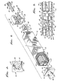
- a column 10, shown In FIG. 1 of the accompanying drawings, Is suitable for use as, for example, a tower leg. It is exemplary of the many structural members that can be constructed In accordance with the present Invention.
- the beam 10 Includes a four-sided, box-like, fiberglass body shell 12.
- the shell 12 is formed by an inner layer 12A that is filament wound parallel to the longitudinal axis of the column 10 and an outer layer 12B that is filament wound perpendicular to the longitudinal axis of the column. This technique for arranging the fibers within the resinous bonding material provides a shell 12 of superior strength. An alternative method of forming the shell 12 would utilize pultrusion.
- each of the bands 14 extends longitudinally throughout the open interior of the shell 12 and is oriented so that one of Its two loop-shaped endless side edges is contiguous with the flat interior surface of a corresponding side of the shell 12. While this band construction is preferred, other types of band, such as woven steel cables, could be used.
- the first end cap 16 is basically a steel plate that interlocks with one end of the shell 12.
- the Inner layer 12A of the shell 12 projects slightly beyond the outer layer 12B and fits Into the end cap to interlock and prevent transverse relative movement (note the right hand side of FIG. 3).
- first end cap 16 On the inside of the first end cap 16 is an Internally formed anchor piece 20 that includes a rectangular support 22 projecting a short distance along the longitudinal axis of the shell 12 and four cylindrical lugs 24 that project radially from the support 22. Each of the lugs 24 is circled by an end of one of the bands 14, as shown In FIG. 3. On the outside of the first end cap 16 is a cross-shaped external fastener 26, the use of which will be explained below.
- the second end cap 18 interlocks with the shell in the same manner as the first end cap 16.
- the second end cap 18 Is of a different construction having two parallel plates 28 and 30 that define a cavity 31 between them.
- the inner plate 28 rests against the end of the shell 12.
- the outer plate 30 Is provided with a cross-shaped openIng 32 that serves as an external fastener.
- This opening 32 is of the same configuration as the male fastener 26 at the opposite end of the column 10, but Is rotationally displaced 45 degrees with respect to the male fastener. Accordingly, two similar columns 10 can be Interlocked by Inserting the male fastener 26 In the opening 32 and then rotating the flat sides of one column until they are aligned (see FIG. 3).
- a movable anchor piece 34 that Includes a large four-sided nut 36 having a threaded opening 38 aligned with the longitudinal axis of the column 10.
- Four radially projecting cylindrical lugs 40 extend from the nut 36 to engage the ends of the bands 14.
- the bands 14 extend between the two anchors 20 and 34.
- a tensioning member 42 that includes a threaded shank 44 and an enlarged convex head 46 at Its outer end.
- the shank 44 extends through a central aperture 48 In the inner plate 28 and is received by the threaded opening 38 of the anchor 34.
- a concave, counter-sunk recess 50 In the outer surface of the Inner plate 28 surrounds the aperture 48 and receives the head 46 of the tensioning member 42. Serrations 52 on the head 46 engage the surface of the recess 50 to prevent undesired rotation of the tensioning member 42.
- the bands 14 are placed within the body shell 12 so that they protrude from the open end where the second end cap 18 is to be positioned.
- the protruding ends can then be looped over the lugs 40 of the movable anchor piece 34.
- the free ends of the bands 14 are then withdrawn from the opposite end of the shell 12 so that the movable anchor piece 34 is pulled into the shell. It is then possible to connect the bands 14 to the lugs 24 of the fixed anchor piece 20.
- the bands 14 and movable anchor piece 34 are then moved back toward the second end cap 18 until the first end cap 16 interlocks with the body shell 12 as explained above.
- the second end cap 18 is then interlocked with the opposite end of the body shell 12 to close the column 10. At this point, the bands 14 are only loosely held. Next, the tensioning member 42 is inserted through the aperture 48 of the second end cap 18 so that the shank 42 engages the threads of the movable end anchor 34.
- the tensioning member 42 carries a break away drive piece 54 that, along with the head 46 to which it is attached, passes through the center of the cross-shaped opening 32 of the second end cap 18.
- the drive piece 54 (hexagonal In this example) is engaged by a suitable tool to rotate the tensioning member 42. Rotation In the proper direction causes the movable anchor 34 to be pulled . toward the second end cap 18. In this manner, the bands 14 are stretched between the two anchors 20 and 34.
- the drive piece 54 breaks off and can be extracted from the second end piece 18 through the cross-shaped opening 32.
- the serrations 52 do not Interfere with rotation of the tensioning member 42 In the direction that increases the tension on the bands 14. They do, however, bite into the surface of the recess 50 to prevent tension reducing counter-rotation.
- the metal end caps 16 and 18 are thus firmly and permanently secured to the body shell 12 by the tension of the bands 14. It Is not necessary to use glue or other mechanical fasteners that would necessarily depend on the strength and integrity of a relatively small portion of the fiberglass shell 12 at the point of attachment.
- the bands 14 strengthen and rigidify the column 10 to inhibit any type of twisting or bowing since at least one of the bands 14, which are in tension, would resist the elongation that would necessarily accompany any such deflection.
- Another function of the bands 14 is to strengthen the sidewalls of the shell 12 which are In contact with the endless loop-shaped side edges of the bands tact, thereby preventing the shell from collapsing.
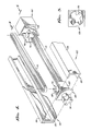
- Another column 60 is also constructed in accordance with the invention but omits the more complex tensioning arrangement of the column 10 described above. It has a multi-directionally wound fiberglass body shell 62 formed by two elongated channel-shaped members 63 that come together to form a four-sided, box-like structure wrapped by a decorative outer layer 64. It is closed at the ends by first and second end caps 65 and 66 that are similar to the end caps 16 and 18 of the beam 10.
- the two columns 10 and 60 differ, however, in that the end caps 65 and 66 of the second column 60 each carry two relatively large plate-like projections 68 that fit into the shall 62.
- the end caps 65 and 66 of the column 60 each carry an anchor piece 70 that forms only two such lugs.
- Each of these anchor pieces 70 Is integrally formed with one of the end caps 65, 66 and thus as a fixed position once a corresponding end cap is In place.
- the bands 72 are looped over the anchor 70 and the two end caps 65 and 66 are pulled apart, gripping them by two external fasteners 74 and 76 similar to the fasteners 26 and 32 of the column 10.
- the channel shaped members 63 are then positioned between the end caps 64 and 66 and the tension of the bands 72 is allowed to pull the end caps toward each other.
- the column 60 can, If desired, be disassembled by reversing these steps.
- the second column 60 retains the advantages of light weight and high strength associated with fiberglass.
- the parameters of the columns 10 and 60 can be varied with relative ease during the manufacturing process by changing the thickness of the fiberglass or varying the materials used without changing external dimensions significantly.
- the rigidity of the columns 10 and 60 can be altered by changing the tension of the bands 14 and 72.
Landscapes
- Engineering & Computer Science (AREA)
- Architecture (AREA)
- Civil Engineering (AREA)
- Structural Engineering (AREA)
- Rod-Shaped Construction Members (AREA)
- Joining Of Building Structures In Genera (AREA)
- Laminated Bodies (AREA)
Applications Claiming Priority (2)
| Application Number | Priority Date | Filing Date | Title |
|---|---|---|---|
| US06/115,502 US4313287A (en) | 1980-01-25 | 1980-01-25 | Internally tensioned structural member and method of assembling same |
| US115502 | 1987-10-30 |
Publications (2)
| Publication Number | Publication Date |
|---|---|
| EP0033187A2 true EP0033187A2 (fr) | 1981-08-05 |
| EP0033187A3 EP0033187A3 (fr) | 1981-09-23 |
Family
ID=22361817
Family Applications (1)
| Application Number | Title | Priority Date | Filing Date |
|---|---|---|---|
| EP81300022A Ceased EP0033187A3 (fr) | 1980-01-25 | 1981-01-06 | Elément de structure mis sous tension interne |
Country Status (4)
| Country | Link |
|---|---|
| US (1) | US4313287A (fr) |
| EP (1) | EP0033187A3 (fr) |
| AU (1) | AU555052B2 (fr) |
| CA (1) | CA1160421A (fr) |
Cited By (4)
| Publication number | Priority date | Publication date | Assignee | Title |
|---|---|---|---|---|
| WO1997010394A3 (fr) * | 1995-09-01 | 1997-03-20 | Juergen Sager | Element porteur sous forme de profile creux pour technique de construction |
| DE19613699C1 (de) * | 1996-03-29 | 1997-10-02 | Juergen Sager | Hohlprofilförmiges Tragelement für die Bautechnik |
| DE19619044C1 (de) * | 1996-05-02 | 1998-02-05 | Juergen Sager | Energiesparendes Fachwerkhaus |
| CN112282208A (zh) * | 2020-11-06 | 2021-01-29 | 安徽军瑶新型材料有限公司 | 一种装配建筑的组装梁结构及其生产方法 |
Families Citing this family (10)
| Publication number | Priority date | Publication date | Assignee | Title |
|---|---|---|---|---|
| US4685253A (en) * | 1981-03-06 | 1987-08-11 | Bitterly Jack G | Structural member |
| US5136822A (en) * | 1989-09-27 | 1992-08-11 | Blum Alan L | Prefabricated building elements |
| GB2283253B (en) * | 1993-10-25 | 1997-04-23 | Euro Stress Ltd | Struts |
| US6484469B2 (en) | 2000-10-19 | 2002-11-26 | William E. Drake | Column structures and methods for supporting compressive loads |
| FR2882421A1 (fr) * | 2005-02-22 | 2006-08-25 | Freyssinet Internat Stup Soc P | Procede de renforcement d'une structure tubulaire metallique et structure resultante |
| DE102009050518B4 (de) * | 2009-10-23 | 2012-09-27 | Audi Ag | Kraftfahrzeug-Strukturteil sowie Verfahren zur Herstellung des Strukturteils |
| US8756874B2 (en) * | 2011-03-21 | 2014-06-24 | The Texas A&M University System | Traffic signal supporting structures and methods |
| US8763320B1 (en) * | 2013-03-01 | 2014-07-01 | National Applied Research Laboratories | Dual-core self-centering buckling-restrained brace |
| CA3157478A1 (fr) * | 2019-11-05 | 2021-05-14 | Timothy P. Squires | Dispositif de mise sous tension et element entraine correspondant |
| US12195965B2 (en) * | 2021-02-19 | 2025-01-14 | University Of South Florida | Cost-effective bulk glass reinforced composite columns |
Family Cites Families (21)
| Publication number | Priority date | Publication date | Assignee | Title |
|---|---|---|---|---|
| US240387A (en) * | 1881-04-19 | Jbeemiah oowdy | ||
| US833263A (en) * | 1905-12-19 | 1906-10-16 | Thomas E Tracy | Foldable box-beam. |
| US1552300A (en) * | 1924-11-26 | 1925-09-01 | Harry G Hersey | Weatherproof pole or post |
| US2016273A (en) * | 1934-09-14 | 1935-10-08 | Harry N Atwood | Built-up composite cellular structure |
| US2303394A (en) * | 1940-02-21 | 1942-12-01 | Schorer Herman | Prestressing reinforced concrete |
| US2347879A (en) * | 1941-04-30 | 1944-05-02 | Selection Engineering Co Ltd | Hollow beam and column for use in buildings |
| BE491207A (fr) * | 1943-10-13 | |||
| US3111569A (en) * | 1958-06-20 | 1963-11-19 | Rubenstein David | Packaged laminated constructions |
| US3087581A (en) * | 1960-03-07 | 1963-04-30 | Pitman Mfg Company | Fiberglas structural member and method of making same |
| US3238690A (en) * | 1960-03-11 | 1966-03-08 | Reinforced Plastic Container C | Composite beam |
| US3237362A (en) * | 1961-07-11 | 1966-03-01 | Howard A Fromson | Structural unit for supporting loads and resisting stresses |
| US3300927A (en) * | 1963-01-21 | 1967-01-31 | Ruberoid Company | Laminated sheet material |
| US3158236A (en) * | 1963-03-12 | 1964-11-24 | Henry P Caligiuri | Fire resistant studs |
| US3327441A (en) * | 1963-12-27 | 1967-06-27 | Union Carbide Corp | Insulating panel assembly with a resinous impregnated support member |
| US3413775A (en) * | 1966-04-13 | 1968-12-03 | Tubular Products Inc | Building structure |
| US3405490A (en) * | 1967-01-10 | 1968-10-15 | Robert R. La Marr | Anchor structure for posttensioned tendons |
| US3698150A (en) * | 1970-06-04 | 1972-10-17 | Shell Oil Co | Bipartite tubular molded synthetic resin furniture part with internal reinforcement |
| US3810337A (en) * | 1970-10-28 | 1974-05-14 | S Pollard | An elongated stressed structural member |
| US3708380A (en) * | 1971-06-21 | 1973-01-02 | Ethyl Corp | Composite sandwich panel type construction |
| JPS523487B2 (fr) * | 1973-01-11 | 1977-01-28 | ||
| US3882650A (en) * | 1974-05-21 | 1975-05-13 | Paul F Gugliotta | Pipe-and-ball truss array |
-
1980
- 1980-01-25 US US06/115,502 patent/US4313287A/en not_active Expired - Lifetime
-
1981
- 1981-01-06 EP EP81300022A patent/EP0033187A3/fr not_active Ceased
- 1981-09-22 CA CA000386369A patent/CA1160421A/fr not_active Expired
- 1981-10-22 AU AU76730/81A patent/AU555052B2/en not_active Ceased
Cited By (5)
| Publication number | Priority date | Publication date | Assignee | Title |
|---|---|---|---|---|
| WO1997010394A3 (fr) * | 1995-09-01 | 1997-03-20 | Juergen Sager | Element porteur sous forme de profile creux pour technique de construction |
| DE19613699C1 (de) * | 1996-03-29 | 1997-10-02 | Juergen Sager | Hohlprofilförmiges Tragelement für die Bautechnik |
| DE19619044C1 (de) * | 1996-05-02 | 1998-02-05 | Juergen Sager | Energiesparendes Fachwerkhaus |
| CN112282208A (zh) * | 2020-11-06 | 2021-01-29 | 安徽军瑶新型材料有限公司 | 一种装配建筑的组装梁结构及其生产方法 |
| CN112282208B (zh) * | 2020-11-06 | 2022-01-25 | 安徽军瑶新型材料有限公司 | 一种装配建筑的组装梁结构及其生产方法 |
Also Published As
| Publication number | Publication date |
|---|---|
| AU7673081A (en) | 1983-04-28 |
| EP0033187A3 (fr) | 1981-09-23 |
| CA1160421A (fr) | 1984-01-17 |
| US4313287A (en) | 1982-02-02 |
| AU555052B2 (en) | 1986-09-11 |
Similar Documents
| Publication | Publication Date | Title |
|---|---|---|
| EP0033187A2 (fr) | Elément de structure mis sous tension interne | |
| JPH032946Y2 (fr) | ||
| US5231752A (en) | Wire rope termination | |
| US4641816A (en) | Apparatus for stretching, loosening, and fixing a wire member | |
| CA1198034A (fr) | Methode et dispositif de renflement d'une tige en acier pour son ancrage dans le beton | |
| KR200448095Y1 (ko) | 풀림 방지 너트 | |
| JP2706175B2 (ja) | 合成材料製連桿 | |
| US3877113A (en) | Anchoring system used in post stressing concrete | |
| US4398377A (en) | Structural member with equalized internal tension | |
| JP2884465B2 (ja) | Frp補強材の端末定着構造 | |
| US3559275A (en) | Method of forming an anchorage for prestress reinforced structural members | |
| KR20160109863A (ko) | 스트랜드별 외부 나사부가 형성된 재긴장 블럭을 이용한 재긴장 가능구성의 긴장재 정착장치 | |
| US4124321A (en) | Adjustable tie rod holder | |
| US3590474A (en) | Method of anchoring pre-stressed wire ropes | |
| DE2511855C3 (de) | Schwungrad mit mehreren Kränzen aus anisotropem Material | |
| US6719241B2 (en) | Cable tie-off device for cable lifts | |
| US4636104A (en) | Structural fixing devices for furniture | |
| CH681548A5 (fr) | ||
| US1738609A (en) | Means for fastening wire fabrics to fence or gate posts and the like | |
| JPH0438354A (ja) | Frpロッドの緊張方法 | |
| KR102427958B1 (ko) | 풍하중에 강한 케이블 보강형 막구조물 | |
| KR100470768B1 (ko) | 에어돔의 케이블시스템 | |
| EP1423327B1 (fr) | Dispositif de tension pour cables et similaires | |
| WO2006121301A1 (fr) | Ensemble boulon d'ancrage | |
| KR200351538Y1 (ko) | 인장케이블 턴버클 유니트 |
Legal Events
| Date | Code | Title | Description |
|---|---|---|---|
| PUAI | Public reference made under article 153(3) epc to a published international application that has entered the european phase |
Free format text: ORIGINAL CODE: 0009012 |
|
| PUAL | Search report despatched |
Free format text: ORIGINAL CODE: 0009013 |
|
| AK | Designated contracting states |
Designated state(s): BE CH DE FR GB IT NL SE |
|
| AK | Designated contracting states |
Designated state(s): BE CH DE FR GB IT NL SE |
|
| 17P | Request for examination filed |
Effective date: 19820202 |
|
| STAA | Information on the status of an ep patent application or granted ep patent |
Free format text: STATUS: THE APPLICATION HAS BEEN REFUSED |
|
| 18R | Application refused |
Effective date: 19840318 |