EP0033218A1 - Sende- und/oder Empfangssystem für Mitteilungen über Rundfunk - Google Patents
Sende- und/oder Empfangssystem für Mitteilungen über Rundfunk Download PDFInfo
- Publication number
- EP0033218A1 EP0033218A1 EP81300264A EP81300264A EP0033218A1 EP 0033218 A1 EP0033218 A1 EP 0033218A1 EP 81300264 A EP81300264 A EP 81300264A EP 81300264 A EP81300264 A EP 81300264A EP 0033218 A1 EP0033218 A1 EP 0033218A1
- Authority
- EP
- European Patent Office
- Prior art keywords
- signal
- message
- master
- transmitters
- frequency
- Prior art date
- Legal status (The legal status is an assumption and is not a legal conclusion. Google has not performed a legal analysis and makes no representation as to the accuracy of the status listed.)
- Granted
Links
- 238000006073 displacement reaction Methods 0.000 claims description 3
- 230000005540 biological transmission Effects 0.000 description 15
- 238000010586 diagram Methods 0.000 description 4
- 230000000694 effects Effects 0.000 description 2
- 230000002238 attenuated effect Effects 0.000 description 1
- 239000013078 crystal Substances 0.000 description 1
- 230000001934 delay Effects 0.000 description 1
- 230000002401 inhibitory effect Effects 0.000 description 1
- 230000000630 rising effect Effects 0.000 description 1
- 238000000926 separation method Methods 0.000 description 1
Images


Classifications
-
- G—PHYSICS
- G08—SIGNALLING
- G08G—TRAFFIC CONTROL SYSTEMS
- G08G1/00—Traffic control systems for road vehicles
- G08G1/09—Arrangements for giving variable traffic instructions
- G08G1/091—Traffic information broadcasting
- G08G1/094—Hardware aspects; Signal processing or signal properties, e.g. frequency bands
-
- H—ELECTRICITY
- H04—ELECTRIC COMMUNICATION TECHNIQUE
- H04H—BROADCAST COMMUNICATION
- H04H20/00—Arrangements for broadcast or for distribution combined with broadcast
- H04H20/65—Arrangements characterised by transmission systems for broadcast
- H04H20/71—Wireless systems
- H04H20/72—Wireless systems of terrestrial networks
-
- H—ELECTRICITY
- H04—ELECTRIC COMMUNICATION TECHNIQUE
- H04H—BROADCAST COMMUNICATION
- H04H40/00—Arrangements specially adapted for receiving broadcast information
- H04H40/18—Arrangements characterised by circuits or components specially adapted for receiving
-
- H—ELECTRICITY
- H04—ELECTRIC COMMUNICATION TECHNIQUE
- H04H—BROADCAST COMMUNICATION
- H04H60/00—Arrangements for broadcast applications with a direct linking to broadcast information or broadcast space-time; Broadcast-related systems
- H04H60/09—Arrangements for device control with a direct linkage to broadcast information or to broadcast space-time; Arrangements for control of broadcast-related services
- H04H60/14—Arrangements for conditional access to broadcast information or to broadcast-related services
- H04H60/15—Arrangements for conditional access to broadcast information or to broadcast-related services on receiving information
-
- H—ELECTRICITY
- H04—ELECTRIC COMMUNICATION TECHNIQUE
- H04H—BROADCAST COMMUNICATION
- H04H2201/00—Aspects of broadcast communication
- H04H2201/70—Aspects of broadcast communication characterised in that receivers can be addressed
Definitions
- the present invention relates to a selective message-broadcasting system.
- Selective message broadcasting systems are used to broadcast interrupting messages, e.g. traffic information messages, to specific geographical areas, whereby listeners hear only those messages relevant to the area within which they are situated.
- interrupting messages e.g. traffic information messages
- the invention is described largely in relation to a motoring service but the invention would be applicable to other services, such as selective paging systems or aircraft or other speech or data communications, where it is desirable to direct messages to particular areas.
- Known selective message-broadcasting systems can either be frequency-division multiplex systems (FMD),-in which a number of messages are broadcast each having a different carrier frequency, or time division multiplex systems (TDM), inwhich the messages have a common carrier frequency and are broadcast one at a time.
- FMD frequency-division multiplex systems
- TDM time division multiplex systems
- the object of the present invention is to provide a system which is suitable for use, inter alia, at very high frequencies.
- a message broadcasting and receiving system comprising a network of transmitters, control means arranged to select a master transmitter or transmitters to transmit a message signal and to cause the or each selected transmitter to preface its message signal with a master code signal, and to cause one or more other transmitters of the network to radiate a slave code signal which is distinct from the master code signal, and a fixed or mobile receiver including a detecting circuit which detects whether the master code signal is received before or after an-instant determined by the reception of a slave code signal and allows- the reception of the message signal, if, and only if, the master code signal is received before the said instant.
- a message-broadcasting system comprising a network of transmitters which, in operation, transmit messages in time division multiplex, a control means arranged to select a master transmitter or transmitters to transmit a message signal and to cause the or each selected transmitter to preface its message with a master code signal and to cause one or more other transmitters of the network to radiate a slave code signal, wherein the master code signal and slave code signal are carrier signals displaced by different amounts from the carrier frequency of the message signal.
- the receiver is able to determine whether or not it is in the master service area by recognising whether or not the code signal which it receives first originated from the or a master transmitter or from the or a slave transmitter. If the master code signal, originating from the nearest master transmitter, is the first signal to be received, the receiver is inside or on the boundary of the master service area and will be demuted, i.e. it will respond to the message following the master signal; if the slave code signal, originating from the nearest slave transmitter, is the first signal to be received, the receiver is outside the master service area and will remain muted, i.e. it will not respond to the message following the master signal. Subsequent arrivals from more distant transmitters during the period in which the code signals are evaluated will have no further effect on the receiver. Such receivers may be fitted in vehicles or may be at fixed locations such as in the homes or elsewhere.
- the present invention further provides a message broadcast receiver comprising a detecting circuit arranged to detect whether a first signal, having a given frequency, is received before an instant determined by the reception of a second signal, having a frequency different to that of the first signal, and allows the reception of a message signal if, and only if, the first signal is received before the said instant.
- the receiver is muted, i.e. it is prevented from receiving further messages. This may be accomplished by using the master transmitter to transmit a signal at the frequency of the slave signals, after the message signal.
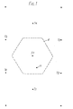
- a network of transmitters Tl, T2 etc. are arranged on an idealized equilateral triangular lattice.
- a practical transmitter to transmitter spacing may be 50km, although the lattice will be distorted to allow for the geographical, attributes of region served by the network.
- T7 is selected as a master transmitter and Tl to T6 are selected as slave-transmitters, defining a master service area 4.
- the master transmitter T7 transmits a master signal, one possible format of which is shown in Fig. 2a, consisting of an initial burst of an unmodulated carrier 6 at a frequency fo-100 kHz.
- the message signal 8 following the initial burst, uses a carrier frequency fo which is frequency modulated by ⁇ 50 kHz.
- the slave transmitters Tl to T6 (Fig. 1) transmit a slave signal, one possible format of which is shown in Figure 2b, consisting of an initial burst of an unmodulated carrier 10 at a different frequency, i.e. fo + 100 kHz, to that of the initial burst of the master signal 6.
- the duration of the master and slave transmission bursts6 and 10 is made longer than the time taken for a signal to travel between the master transmitter T7 and the slave transmitters Tl to T6, e.g., a transmission burst of 2ms for a master/slave transmitter separation of 60 km. This prevents erroneous operation of the receiver.
- a receiver 11 includes an aerial 12 and V.H.F. crystal controlled RF stages 14 which receive the transmitted signals 6, 8 and 10.
- the output from the RF stages 14 is applied to an FM discriminator 16.
- the discriminator 16 is so designed that, on receiving the master transmission burst 6 ( Figure 2a), at a frequency of fo-100 kHz, it will produce a positive d.c. voltage shift of say 1 volt whereas, on receiving the slave transmission burst 10 ( Figure 2b), at a frequency of fo+100 kHz, it will produce a negative d.c. voltage shift of similar amplitude.
- the presence of the message signal 8 at the input to the discriminator 16 will not cause the discriminator output to vary by more than say - 0.5 velts.
- the output of the FM discriminator 16 divides along two separate paths 30 and 36.
- the path 36 forms the input to a voltage comparator 18 which recognises the ⁇ 1 volt shifts of the FM discriminator 16 but ignores the - 0.5 volt variations caused by the message signal 8.
- the voltage comparator 18 receives an input from the discriminator 16. The input is applied to one terminal of two comparator amplifiers 38 and 40. The other terminal of each comparator amplifier 38 and 40 is connected to a potentiometer 42 and 44 respectively.
- Transistor amplifiers 46 and 48 are connected to the respective outputs of the comparator amplifiers 38 and 40.
- the potentiometer 42 is so adjusted that the master code signal fo-100 kHz produces a logic 1 level on the output 50 of the transistor amplifier 46.
- the potentiometer 44 is so adjusted that the slave code signal fo+100 kHz produces a logic 1 level on the output 52 of the transistor amplifier 48.
- the output 50 is connected through cascaded inverters 54 and 58 to the D input of aD-type flip-flep 62 in a timing comparator 20.
- the outputs 50 and 52 are connected to a NOR gate 56 whose output is connected through an inverter 60 to the clock terminal CK of the flip-flop.
- the Q output of the flip-flop is applied to an audio switch 22 (Fig. 3) and, when the flip-flop is set, the switch completes the audio path 30 between the discriminator 16 and AF stages 24 connected to a loudspeaker 32.
- the receiver is thus demuted.
- the switch 22 can simultaneously mute an alternative audio source normally feeding the speaker 32.
- the flip-flop 62 set provided that the master code signal was received about 5 ⁇ s before the slave code signal.
- the receiver 11 After the message signal 8 (Fig. 2) has been received, the receiver 11 is muted, i.e. the audio switch 22 is turned off. To do this the flip-flop 62 is reset, by broadcasting a transmission burst 13 (Fig. 2), from the master transmitter T7, at the frequency of fo+100 kHz after the message signal 8, i.e. the frequency normally considered to be that of the slave transmitters T1 to T6. The flip-flop is therefore clocked with the D-input false.
- each service area 4 may be varied by delaying the switch-on of the master or slave transmission bursts 6 and 10.
- the boundary will be moved towards the mastertransmitter, i.e. the master service area will be reduced.
- the switch-on of a slave transmission burst 10 the boundary will be moved towards the slave transmission in question, thus increasing the master service area.
- the system has the further advantage that, should a particular transmitter fail, the service areas of the transmitter surrounding it automatically expand and thus tend to take its place. Furthermore, since the system relies on the fact that the receiver 11 makes its decision on the first signal to arrive at its input and ignores subsequent arrivals, multipath reception at the receiver is unlikely to cause difficulties.
- Additional coded signals may be transmitted either immediately before or immediately after the start code or could form the start code signal that could indicate, for example, particular classes of recipient for whom the message that follows is intended, and/or whether the message is a repeat of one that has previously been broadcast, or other features of the message. Such additional signals would enable receivers to disregard irrelevant messages.
- a master controller 64 (Fig. 4) is able to communicate with all the transmitters in the network by means of land lines, or the equivalent, but is here shown linked to only one of the transmitters.
- the master controller distributes the messages which the different transmitters are to broadcast, in conjunction with a prefixed digital address code which selects the transmitter which is to broadcast the message.
- the address code is followed by a master transmission burst 6 (Fig. 2), then the message signal 8 (Fig. 2) itself and finally the second transmission burst 12 (Fig. 2).
- the controller 64 may be simply a preset device which emits the digital codes and messages to a predetermined time schedule or it may utilize a computer to determine the scheduling of transmitters in accordance with requirements.
- Each transmitter (Fig. 4) includes a control demodulator 66 which demodulates the digital codes in a manner well known in data communication.
- the digital codes are fed to a control decoder 68 which recognises, from the address code, whether its transmitter is to radiate the master transmission burst 6 and the message 8, or the slave transmission burst 10, or to remain quiescent.
- the transmitter comprises a drive stage 70 feeding RF output stages 72 and an aerial 74 through an FM message modulator 76, an oscillator 77 providing the carrier frequency fo to the drive circuits 70.
- a 100 kHz oscillator 88 and a mixer 85 modulate fo with 100 kHz to provide sidebands fo ⁇ 100 kHz which are separately filtered out- by lower and upper sideband band-pass filters 84 and 86.
- the control decoder 68 is used to control various switches as follows, as commanded by demodulated control signals. If the transmitter is to transmit switch 78 is closed. If the transmitter is selected as master transmitter, a switch 80 is then closed for 2 ms to radiate the master code signal fo-100 kHz. A switch 82 is then closed to enable the message sent over the land line to be applied to the modulator 76. At the conclusion of the message, a switch 83 is closed for 2 ms to radiate the slave code signal fo + 100 kHz, which re-mutes the receivers which were de-muted by the master code signal.
- the transmitter is selected as a slave, only the switch 83 is closed for 2 ms to radiate the slave code signal.
Landscapes
- Engineering & Computer Science (AREA)
- Signal Processing (AREA)
- Multimedia (AREA)
- Physics & Mathematics (AREA)
- General Physics & Mathematics (AREA)
- Computer Networks & Wireless Communication (AREA)
- Mobile Radio Communication Systems (AREA)
Applications Claiming Priority (2)
| Application Number | Priority Date | Filing Date | Title |
|---|---|---|---|
| GB8003003A GB2068685A (en) | 1980-01-29 | 1980-01-29 | Selective message broadcasting system |
| GB8003003 | 1980-01-29 |
Publications (2)
| Publication Number | Publication Date |
|---|---|
| EP0033218A1 true EP0033218A1 (de) | 1981-08-05 |
| EP0033218B1 EP0033218B1 (de) | 1983-11-23 |
Family
ID=10510976
Family Applications (1)
| Application Number | Title | Priority Date | Filing Date |
|---|---|---|---|
| EP81300264A Expired EP0033218B1 (de) | 1980-01-29 | 1981-01-21 | Sende- und/oder Empfangssystem für Mitteilungen über Rundfunk |
Country Status (3)
| Country | Link |
|---|---|
| EP (1) | EP0033218B1 (de) |
| DE (1) | DE3161447D1 (de) |
| GB (1) | GB2068685A (de) |
Cited By (3)
| Publication number | Priority date | Publication date | Assignee | Title |
|---|---|---|---|---|
| EP0347355A1 (de) * | 1988-06-17 | 1989-12-20 | France Telecom | Synchronisierter multi-thematischer Informationen-Rundfunk, der eine über einen Sendepark rekonfigurierbare Hörstrategie von Radioprogrammen erlaubt |
| AU595982B2 (en) * | 1987-02-04 | 1990-04-12 | Overseas Telecommunications Commission (Australia) | Communication link connection means |
| FR2662685A1 (fr) * | 1990-05-30 | 1991-12-06 | Us Energy | Methode d'extraction d'atomes de metal et d'explosifs d'une solution aqueuse a l'aide de cellules vegetales en suspension. |
Families Citing this family (1)
| Publication number | Priority date | Publication date | Assignee | Title |
|---|---|---|---|---|
| US4539707A (en) * | 1982-06-01 | 1985-09-03 | Aerotron, Inc. | Compressed single side band communications system and method |
Citations (2)
| Publication number | Priority date | Publication date | Assignee | Title |
|---|---|---|---|---|
| DE1183556B (de) * | 1963-01-16 | 1964-12-17 | Japan Radio Co Ltd | UEberlagerungsempfaenger fuer ein Hyperbelnavigationssystem |
| DE2801142B1 (de) * | 1978-01-12 | 1979-07-19 | Werner Ing Weisser | Verfahren zur Navigation und Standortbestimmung eines Fahrzeuges |
-
1980
- 1980-01-29 GB GB8003003A patent/GB2068685A/en not_active Withdrawn
-
1981
- 1981-01-21 EP EP81300264A patent/EP0033218B1/de not_active Expired
- 1981-01-21 DE DE8181300264T patent/DE3161447D1/de not_active Expired
Patent Citations (2)
| Publication number | Priority date | Publication date | Assignee | Title |
|---|---|---|---|---|
| DE1183556B (de) * | 1963-01-16 | 1964-12-17 | Japan Radio Co Ltd | UEberlagerungsempfaenger fuer ein Hyperbelnavigationssystem |
| DE2801142B1 (de) * | 1978-01-12 | 1979-07-19 | Werner Ing Weisser | Verfahren zur Navigation und Standortbestimmung eines Fahrzeuges |
Non-Patent Citations (3)
| Title |
|---|
| DR. INGO WILMANNS "RADAR UND FUNKNAVIGATION", VogelVerlag, Wurzburg, pages 105-114 * |
| FUNKSCHAU, Heft 14, Juli 1980, Franzis Verlag, Munchen ING. PETER ADVIAN "TI-9 900 - ein Loran-C-Navigationsautomat", pages 50-53 * |
| wireless world, vol. 84, january 1978, london, dorset house s.m. edwardson "traffic information broadcasting", pages 28-32 page 29, left column, line 52, right column, last line * |
Cited By (4)
| Publication number | Priority date | Publication date | Assignee | Title |
|---|---|---|---|---|
| AU595982B2 (en) * | 1987-02-04 | 1990-04-12 | Overseas Telecommunications Commission (Australia) | Communication link connection means |
| EP0347355A1 (de) * | 1988-06-17 | 1989-12-20 | France Telecom | Synchronisierter multi-thematischer Informationen-Rundfunk, der eine über einen Sendepark rekonfigurierbare Hörstrategie von Radioprogrammen erlaubt |
| FR2633122A1 (fr) * | 1988-06-17 | 1989-12-22 | France Etat | Diffusion synchronisee d'informations multithematiques permettant une strategie d'ecoute reconfigurable sur un parc d'emetteurs et de programmes hertziens |
| FR2662685A1 (fr) * | 1990-05-30 | 1991-12-06 | Us Energy | Methode d'extraction d'atomes de metal et d'explosifs d'une solution aqueuse a l'aide de cellules vegetales en suspension. |
Also Published As
| Publication number | Publication date |
|---|---|
| EP0033218B1 (de) | 1983-11-23 |
| DE3161447D1 (en) | 1983-12-29 |
| GB2068685A (en) | 1981-08-12 |
Similar Documents
| Publication | Publication Date | Title |
|---|---|---|
| EP0128209B1 (de) | Verfahren zum einstellen von funksendern für synchrone funkübertragung | |
| CA1059216A (en) | Vehicle repeater prioritization system | |
| GB550193A (en) | Improvements in and relating to multiplex frequency-modulation systems | |
| KR890004526A (ko) | 제어모듈 및 이를 구비한 무선통신 시스템 | |
| KR840006896A (ko) | 데이타 통신 시스템용 제어장치 | |
| ES476288A1 (es) | Un metodo para transmitir dos mensajes diferentes sobre una onda portadora por un unico canal de transmision de anchura de banda predeterminada. | |
| EP0853400A3 (de) | Funkübertragungsverfahren für digitale Multimediendatensignale zwischen Teilnehmerstationen in einem lokalen Netzwerk | |
| US2425066A (en) | Pulsed multiplex system employing different width and repetition frequencies for each channel | |
| US4584708A (en) | Communication system, and transmitter therefor, including special announcement recognition | |
| US5054113A (en) | Communication system with bit sampling method in portable receiver for simulcast communication | |
| US3534266A (en) | System for automatic transmission and reception of repetitive programs | |
| EP0033218B1 (de) | Sende- und/oder Empfangssystem für Mitteilungen über Rundfunk | |
| JPH06181460A (ja) | 共通周波数放送網で地域的に異なる情報を伝送する方法 | |
| US4800391A (en) | Method of and apparatus for message communication on Loran-C navigational signal broadcasts and the like with reduced navigation errors | |
| US2509218A (en) | Repeater link system | |
| GB1591159A (en) | Message-broadcasting systems | |
| GB2314237A (en) | Communications system | |
| GB1355803A (en) | Road traffic information communication system | |
| US4621262A (en) | Method of and a system for remote control of electronic equipments | |
| JPS6329860B2 (de) | ||
| EP2782266B1 (de) | Satelliten Kommunikationssystem unter Verwendung hierarchischer Modulation um eine Vielzahl von modulierten Signale von hoher und niedriger Priorität zu übertragen. | |
| KR100292952B1 (ko) | 이동통신 시스템에서 통화 권역 확장장치 | |
| JP6437594B1 (ja) | 同報通信システム、情報提供装置および信号送信方法 | |
| KR20250174223A (ko) | 차량용 라디오 장치 및 이의 제어방법 | |
| Shelswell et al. | Digital audio broadcasting |
Legal Events
| Date | Code | Title | Description |
|---|---|---|---|
| PUAI | Public reference made under article 153(3) epc to a published international application that has entered the european phase |
Free format text: ORIGINAL CODE: 0009012 |
|
| AK | Designated contracting states |
Designated state(s): CH DE FR NL |
|
| 17P | Request for examination filed |
Effective date: 19811118 |
|
| GRAA | (expected) grant |
Free format text: ORIGINAL CODE: 0009210 |
|
| AK | Designated contracting states |
Designated state(s): CH DE FR LI NL |
|
| PG25 | Lapsed in a contracting state [announced via postgrant information from national office to epo] |
Ref country code: NL Effective date: 19831123 |
|
| PGFP | Annual fee paid to national office [announced via postgrant information from national office to epo] |
Ref country code: FR Payment date: 19831201 Year of fee payment: 4 |
|
| REF | Corresponds to: |
Ref document number: 3161447 Country of ref document: DE Date of ref document: 19831229 |
|
| ET | Fr: translation filed | ||
| PG25 | Lapsed in a contracting state [announced via postgrant information from national office to epo] |
Ref country code: LI Effective date: 19840131 Ref country code: CH Effective date: 19840131 |
|
| PGFP | Annual fee paid to national office [announced via postgrant information from national office to epo] |
Ref country code: DE Payment date: 19840328 Year of fee payment: 4 |
|
| NLV1 | Nl: lapsed or annulled due to failure to fulfill the requirements of art. 29p and 29m of the patents act | ||
| PLBE | No opposition filed within time limit |
Free format text: ORIGINAL CODE: 0009261 |
|
| STAA | Information on the status of an ep patent application or granted ep patent |
Free format text: STATUS: NO OPPOSITION FILED WITHIN TIME LIMIT |
|
| REG | Reference to a national code |
Ref country code: CH Ref legal event code: PL |
|
| 26N | No opposition filed | ||
| PG25 | Lapsed in a contracting state [announced via postgrant information from national office to epo] |
Ref country code: FR Free format text: LAPSE BECAUSE OF NON-PAYMENT OF DUE FEES Effective date: 19850930 |
|
| PG25 | Lapsed in a contracting state [announced via postgrant information from national office to epo] |
Ref country code: DE Effective date: 19851001 |
|
| REG | Reference to a national code |
Ref country code: FR Ref legal event code: ST |