EP0033223A2 - Schwingungsdämpfer für aufgehängte Freileitungen und Kabel - Google Patents
Schwingungsdämpfer für aufgehängte Freileitungen und Kabel Download PDFInfo
- Publication number
- EP0033223A2 EP0033223A2 EP81300274A EP81300274A EP0033223A2 EP 0033223 A2 EP0033223 A2 EP 0033223A2 EP 81300274 A EP81300274 A EP 81300274A EP 81300274 A EP81300274 A EP 81300274A EP 0033223 A2 EP0033223 A2 EP 0033223A2
- Authority
- EP
- European Patent Office
- Prior art keywords
- conductor
- piston
- vibration absorber
- conductors
- cylinder
- Prior art date
- Legal status (The legal status is an assumption and is not a legal conclusion. Google has not performed a legal analysis and makes no representation as to the accuracy of the status listed.)
- Withdrawn
Links
Images


Classifications
-
- H—ELECTRICITY
- H02—GENERATION; CONVERSION OR DISTRIBUTION OF ELECTRIC POWER
- H02G—INSTALLATION OF ELECTRIC CABLES OR LINES, OR OF COMBINED OPTICAL AND ELECTRIC CABLES OR LINES
- H02G7/00—Overhead installations of electric lines or cables
- H02G7/14—Arrangements or devices for damping mechanical oscillations of lines, e.g. for reducing production of sound
Definitions
- the present invention relates to electrical power transmission and communication systems and in particular to vibration absorbers for use with aerially suspended conductors and cables.
- an aero-elastic system such as constituted by an overhead transmission, distribution and/or communication line is subject to three different types of vibration phenomenon. Unless these phenomenon are eliminated or severely reduced they may result in premature failure of the conductors or cables, (hereinafter referred to collectively as conductors), disruption of service or damage to the support structures.
- the vibrational modes are observed as standing waves and have been characterised in the art as follows.
- a low frequency, large amplitude motion of conductors that usually occurs under wind and ice conditions is known as conductor galloping.
- the amplitudes of the galloping motion can reach a value equal to twice the conductor sag and the frequency can range from a single loop or fundamental span frequency of 0.1 Hz to a 3 loop, third harmonic frequency of 1.0 Hz.
- a medium amplitude, medium frequency motion of bundle conductors is known as sub-conductor oscillation.
- the amplitude of this oscillation is mainly in a horizontal plane and can exceed the normal bundle spacing.
- the frequency of this oscillation is typically in the range of 1 to 3 Hz.
- a high frequency and small amplitude motion that occurs on both single and bundle conductors is known as aeolian vibration. This vibration can reach an amplitude of two or three times the conductor diameter.
- the frequency of aeolian vibration is typically in the range of about 5 Hz to 70 Hz.
- dampers used on bundle conductors invariably require a large mass and a resilient member within their mechanism to reduce the amplitude of vibration.
- This resilient member has conventionally taken the form of a spring although elastomeric members have also been used. Such members must be designed for a service life in the order of 20 years and are therefore relatively expensive.
- the spring-mass system is inherently frequency dependent so its effectiveness is limited to a certain range of frequencies of oscillation and the dampers also require careful and precise placement along the span of the conductor. To be effective, such dampers require placement at the lambda by four (k/4) wave point of the centre aeolian frequency of the conductor. Further, the use of a large mass imposes additional stresses on the conductors or cables which further limits the tension that may be applied to the conductors.
- spacer dampers have been developed which seek to combine within one structure the properties of a spacer and a damper. Although these have met with some success they are necessarily a compromise between the respective properties required from a spacer and a damper.
- a vibration absorber for an aero-elastic system comprising attachment means for connecting the absorber to a conductor system, a first member connected to the connecting means, a second member slidably supported on the first member and movable relative thereto and absorbing means operable between the first and second members upon relative movement therebetween, the absorbing means having a dissipative mechanical impedance of value R to inhibit reflection of a travelling wave propagated on the conductor whereby a travelling wave generated on the conductor is absorbed.
- the principle of the present invention is based upon a further understanding of the vibration phenomenon.
- the applicants have recognized that aeolian vibration and sub-conductor oscillation derive their excitation from the minute forces associated with the release of vortices on the leeward side of conductors and cables when conductors and cables are subjected to a steady air flow across their surface. It is believed that the excitation of aeolian vibration is derived from the detachment of the vortices and that sub-conductor oscillation is derived from the flow of the released vortices past the leeward conductor.
- This release of vortices produces a travelling wave which proceeds along the span in opposite directions from its origin towards the suspension points. This in turn releases other vortices to reinforce and amplify the wave motion.
- the travelling wave arrives at the suspension point of the conductor, that is the attachment point of the conductor to the supporting structure it is reflected as a negative wave due to the rigidity of the support point.
- the damping characteristics of the conductor and the suspension hardware are very small so that attenuation of the travelling waves is also very small. This allows the travelling wave to make a large number of passes in a given span to thereby generate a standing wave having an amplitude of constant value, the amplitude being determined by the damping of the system.
- the present invention provides an absorber which will absorb the travelling wave and prevent its reflection back along the conductor. This is achieved by matching the dissipative impedance of the absorber with the characteristic mechanical impedance of the conductor.
- the characteristic mechanical impedance of a conductor is defined as the ratio of force and velocity amplitudes of the travelling waves. Since the mechanical impedance of the conductor is a function of the tension in the conductor and the mass of the conductor per unit length, an absorber can be designed to match the mechanical impedance of the conductor for any given installation.
- the absorber may be placed at-any convenient location along the span of the conductor and not, as previously described, just at ⁇ /4 wavepoints of the centre aeolian frequency in the conductor.
- the absorber impedance R should be k ⁇ TM where T is the tension of the conductor and M is the mass of the conductor per unit length and k is the damping factor which, under the aforementioned ideal conditions, equals 2.0 to reflect the fact that the conductor extends in both directions from the absorber. It has been found that significant improvements in vibration control may be achieved by selecting an absorber impedance R in the range of 0.5 ⁇ TM to 2 rTM. Thus increases in T and M due to icing of the conductors will not unduly affect the operation of the absorber.
- the principle may be applied to sub-conductor oscillation by utilizing the inertial mass of other bundle conductors to provide support for the second member.
- a vibration absorber at an angle 45° in the range of 30 0 to 60° from the vertical and horizontal planes it will absorb the travelling waves associated with the build-up of both vertical aeolian vibration and horizontal sub-conductor oscillation.
- an electrical power transmission system 10 includes a number of towers 12 (two of which are shown) which are used to support conductors l4, 15 above the ground. It will be appreciated that whereas a two-conductor bundle has been shown in Figure 1, the arrangement is representative of aerially suspended power transmission systems in which a number of phases, each phase consisting of single or bundles of two, three, four or more conductors, are suspended between common support points on the towers.
- the conductors l4, 15 are connected to the towers 12 by means of insulator strings l6.
- insulator strings l6 Various arrangements are available for attaching the insulator strings to the towers and likewise for attaching the insulator strings to the conductors. Since these are of conventional design they will not be described in further detail herein.
- Vibration absorbers l8 are located at appropriate points on the conductors l4, 15 between the towers 12 and rigid spacers 20 of known construction.
- Wind blowing across the surface of the conductors l4, 15 will cause a vortex to form on the leeward side of the conductor. Detachment of the vortex will provide a small force impulse and a displacement of the conductor which will proceed as travelling waves towards each tower 12.
- the vibration absorber l8 comprises a pair of attachment means in the form of clamps 22, 23 which encompass the respective conductor l4, 15 to secure the absorber 18 to the conductors.
- the clamps 22, 23 may be of any suitable form such as are conventionally used for connecting support hardware to conductors.
- the clamp 22 is attached by means of an articulated joint 24 to a first member or body 26.
- the body 26 has end members 28 and 30 which are interconnected by a cylindrical wall portion 32.
- the body portion 26 provides an air tight sealed container.
- the wall portion 32 extends beyond the end member 30 to form a skirt 37.
- the skirt 37 protects the aperture 33 from icing and thereby ensures that the piston rod 36 is freely movable.
- a piston 34 is slidably received within the wall portion 32 and a piston rod 36 is connected to the piston 34.
- the piston rod 36 extends through the end member 30 by means of a tightly fitted aperture 33. Seals may be provided between the end member 30 and the piston rod 36 if desired.
- An orifice 38 is provided through the piston 34 and thereby interconnects chambers 40 and 42 formed between the piston 34 and the end members 28 and 30 respectively.
- the detachment of a vortex from the conductor l4 causes a travelling wave to be propagated.
- the travelling wave approaches the absorber it displaces the body 26.
- the piston 34 and rod 36 remain stationary.
- the volume of the chamber 42 is decreased and air or some other suitable fluid is displaced through the orifice 38 into the chamber 40.
- the energy required to displace the fluid is derived from the travelling wave and therefore the wave is largely absorbed by the absorber 18 having proper sizing of the orifice 38 for a given fluid.
- the travelling wave therefore is not reflected at the connection of the clamp 22.
- the wave travelling toward the tower is reflected at the tower and travels to the absorber where it is also absorbed. In the result, the formation of a standing wave is thereby avoided.
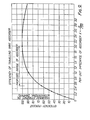
- absorber efficiencies vary as a function of the damping factor k.
- Known spacer dampers which typically have damping factors in the lower ranges as indicated can be seen to be relatively inefficient in absorbing travelling wave energy.
- the damping required from the vibration absorber to provide optimum absorption of the travelling waves on the conductor is equal to 2.0 ⁇ TM where T is the tension in the conductor in pounds and M is the conductor mass per unit length. It has been found however that satisfactory absorption of the travelling wave is achieved if the damping of the absorber is between 0.5 ⁇ TM and 2.0 ⁇ TM.
- the inertial mass of the conductor 15 provides a reasonably stationary working platform.
- the conductor 14 will provide a reasonably stationary working platform for absorption of a travelling wave in conductor 15.
- the vibration absorber 18 does not utilize a spring or resilient member and as such is not frequency dependent. This enables the absorber to be effective over a wide range of conditions. Where a rigid spacer frame is required between the towers the conductor is effectively divided into two sub-spans and an absorber is applied in each sub-span.
- FIG. 2 The embodiment shown in Figure 2 is useful for a two conductor bundle.
- the embodiments of Figures 3 and 4 show arrangements in which the same vibration absorbers are used with multiple conductor bundles to absorb the travelling waves associated with aeolian and sub-conductor oscillations.
- Figure 3 shows an arrangement in which the absorber l8 is employed with a three conductor bundle.
- the conductors 44, 45, 46 are located at the apexes of an equilateral triangle and rigid spacers 47 are used to maintain the desired spacing at appropriate intervals.
- An absorber 18a extends from the conductor 44 to the conductor 45 and similarly an absorber 18b extends from the conductor 44 to the conductor 46.
- Each absorber 18a, 18b is constructed in the manner shown in Figure 2.
- a travelling wave will move along the conductor 45 and will cause relative displacement of the body 26 of the damper 18a.
- the conductor 44 will provide a working platform for the absorber l8a so that the travelling wave is absorbed.
- Figure 4 shows an arrangement in which absorbers are mounted on a four-conductor bundle.
- the conductors are arranged on the corners of a square and the absorbers extend between diagonally opposed conductors. In this manner a working platform is provided for each conductor by the diagonally opposed conductor.
- Figures 5 to 8 show arrangements in which a plurality of absorbers are mounted on a common support frame.
- Figure 5 shows a vibration absorber 50 which is used to control vibrations in a pair of conductors 52 and 54.
- the absorber 50 includes a pair of piston and cylinder devices, 56 and 58, connected respectively to the conductors 52 and 54.
- the piston and cylinder devices 56 and 58 are disposed at 45 0 to the horizontal and vertical planes and as such are effective in absorbing travelling waves in both the vertical and horizontal planes. Since each of the piston-cylinder devices 56 and 58 are identical, only one will be described herein.
- the piston and cylinder device 56 includes a clamp 60 which encompasses and is secured to the conductor 52.
- the clamp is connected to a first member or cylinder 66.
- a piston 68 is slidably received within the cylinder 66 and is attached to a piston rod 62 which extends through an end wall 64 of cylinder 66 by means of a tightly fitting aperture.
- An orifice 70 is provided in the piston 68 to permit flow of air or some other suitable fluid between chambers 72 and 74 defined in the cylinder 66 by the piston 68.
- the piston rod 62 is secured to a common suppr -t frame 76.
- the frame 76 should be as light as possiole to reduce the loading on the conductors. It is not necessary to provide a large mass since the conductors provide a stationary working platform.
- the support frame 76, piston and cylinder device 58 and the second conductor 54 constitute a relatively stationary inertial mass and the cylinder 66 is displaced relative to the piston 68 to cause a displacement of working fluid between the chambers 72 and 74. This absorbs the energy of the travelling wave and thereby inhibits the formation of a standing wave.
- FIG. 6 A similar arrangement is shown in Figure 6 in which a rotational piston and cylinder device is utilized.
- the piston and cylinder device comprises a peripheral wall 80 with a pair of radially extending end walls 82, 84.
- a shaft 86 extends between and is supported by the end walls 82, 84 and a radial vane 88 is integrally formed with the shaft 86.
- the vane 88 extends into sealing contact with the peripheral wall 80 and has an orifice 90 extending therethrough.
- a partition 92 is provided within the cylinder and is attached to the peripheral wall 80.
- a pair of chambers 94 and 96 are defined between the partition member 92 and the vane 88.
- a crank 98 is attached to one end of the shaft 86 and is connected to a clamp member 100 which encompasses the conductor.
- the piston and cylinder device is supported on a support frame 102.
- This embodiment of the invention is also useful in controlling conductor galloping.
- Conductor galloping is initiated by a travelling wave which results in a vertical displacement of a conductor. With a multiple conductor bundle, this induces a rocking of the bundle.
- the absorber shown in Figure 6 is effective in absorbing the rocking motion and thereby inhibits conductor galloping.
- Figure 7 shows an arrangement in which piston and cylinder devices similar to those described in Figure 5 are utilized with a three-conductor bundle. The details of the piston and cylinder devices will not be repeated since they are similar to those shown in Figure 3. It will be appreciated that with piston and cylinder devices extending upwards the piston and cylinder components are oriented so that the skirted portion of the cylinder projects downwardly. In this manner, accumulations of ice which could otherwise impede the operation of the piston and cylinder device are avoided.
- a support frame 76 is used to maintain the piston and cylinder devices at the apices of the triangle. With this arrangement the relatively stationary mass is provided by the undisturbed conductors.
- Figure 8 shows an arrangement for use with a four-conductor bundle. Again piston and cylinder devices similar to those shown in Figure 3 are utilized at the corners of a square support frame 110. This enables the undisturbed conductors to provide the necessary stationary platform to enable damping of the disturbed conductor.
- a four-conductor bundle could utilize a pair of diagonal struts similar to those shown in Figure 6 to provide damping between diametrically opposite conductors of the bundle.
- damper on a single conductor. In this situation it is necessary to provide a working platform by means of a mass.
- This mass may be located within the cylinder of the damper or could be attached to one end of the piston rod.
- the mass would be supported relative to the cylinder by means of a spring which would be chosen so that the resonant frequency of the spring mass system is below the excitation frequency of the vortex detachment frequency.
- a fluid such as silicone oil which offers less variation of viscosity over a wide temperature range, than hydrocarbon oils, thereby maintaining the impedance R within acceptable limits.
Landscapes
- Vibration Prevention Devices (AREA)
- Suspension Of Electric Lines Or Cables (AREA)
Applications Claiming Priority (2)
| Application Number | Priority Date | Filing Date | Title |
|---|---|---|---|
| CA000344328A CA1151256A (en) | 1980-01-24 | 1980-01-24 | Subspan oscillation and aeolian vibration absorber for single and bundle conductors |
| CA344328 | 1980-01-24 |
Publications (2)
| Publication Number | Publication Date |
|---|---|
| EP0033223A2 true EP0033223A2 (de) | 1981-08-05 |
| EP0033223A3 EP0033223A3 (de) | 1981-12-23 |
Family
ID=4116101
Family Applications (1)
| Application Number | Title | Priority Date | Filing Date |
|---|---|---|---|
| EP81300274A Withdrawn EP0033223A3 (de) | 1980-01-24 | 1981-01-21 | Schwingungsdämpfer für aufgehängte Freileitungen und Kabel |
Country Status (6)
| Country | Link |
|---|---|
| US (1) | US4346255A (de) |
| EP (1) | EP0033223A3 (de) |
| AR (1) | AR224798A1 (de) |
| AU (1) | AU6650381A (de) |
| BR (1) | BR8100389A (de) |
| CA (1) | CA1151256A (de) |
Cited By (6)
| Publication number | Priority date | Publication date | Assignee | Title |
|---|---|---|---|---|
| WO1986006560A1 (en) * | 1985-04-22 | 1986-11-06 | Riganti S.P.A. | Vibration damper for a conductor on an overhead electric line |
| DE4135120A1 (de) * | 1991-10-24 | 1993-04-29 | Abb Patent Gmbh | Daempfungseinrichtung |
| DE4400618A1 (de) * | 1993-01-13 | 1994-07-14 | Bergner Richard Gmbh Co | Hochspannungs-Freileitung mit Dämpfungsvorrichtung |
| US5801329A (en) * | 1993-01-13 | 1998-09-01 | Richard Bergner Gmbh & Co. | Outdoor power line having a damping device |
| CN110429542A (zh) * | 2019-07-19 | 2019-11-08 | 上海永大电器有限公司 | 一种用于真空断路器的减震固线装置 |
| CN120073583A (zh) * | 2025-04-29 | 2025-05-30 | 广州海洋地质调查局三亚南海地质研究所 | 一种用于固定海底线缆的锚固装置 |
Families Citing this family (16)
| Publication number | Priority date | Publication date | Assignee | Title |
|---|---|---|---|---|
| CA2450089A1 (en) * | 2003-11-19 | 2005-05-19 | Trevor Haskett | Stay cable damper |
| US7547843B2 (en) * | 2006-12-28 | 2009-06-16 | 3M Innovative Properties Company | Overhead electrical power transmission line |
| US7921005B2 (en) * | 2006-12-28 | 2011-04-05 | 3M Innovative Properties Company | Method for selecting conductors of an overhead power transmission line |
| US7687710B2 (en) * | 2006-12-28 | 2010-03-30 | 3M Innovative Properties Company | Overhead electrical power transmission line |
| CN101692567B (zh) * | 2009-09-24 | 2011-09-28 | 中国电力科学研究院 | 悬摆式阻尼型防舞装置 |
| CN101859988B (zh) * | 2010-03-12 | 2013-01-09 | 湖北省输变电工程公司 | 装配式架线施工工艺 |
| RU2462548C2 (ru) * | 2010-05-12 | 2012-09-27 | Солетанш Фрейсине | Способ демпфирования колебаний вант и соответствующая система |
| CN102545124B (zh) * | 2012-01-09 | 2014-03-26 | 广东电网公司电力科学研究院 | 一种具有自适应调频功能的输电线路防舞装置 |
| US20140021327A1 (en) * | 2012-07-18 | 2014-01-23 | Elwha Llc | Adjustable suspension of transmission lines |
| US9136683B2 (en) * | 2012-07-18 | 2015-09-15 | Elwha Llc | Adjustable suspension of transmission lines |
| CN107026420B (zh) * | 2016-02-02 | 2020-07-24 | 中国电力科学研究院 | 一种弹阻型的半分裂数间隔导线线夹间隔棒 |
| CN106356792B (zh) * | 2016-11-15 | 2017-12-22 | 温州电力设计有限公司 | 油气阻尼防舞器 |
| WO2021247982A1 (en) * | 2020-06-04 | 2021-12-09 | Virginia Tech Intellectual Properties Inc. | Autonomous robot for power line vibration control and inspection |
| US20230029221A1 (en) * | 2021-07-22 | 2023-01-26 | Nec Laboratories America, Inc | Galloping monitoring of overhead transmission lines using distributed fiber optic sensing |
| CN113696796B (zh) * | 2021-08-27 | 2023-03-31 | 中车青岛四方机车车辆股份有限公司 | 接触网防舞动装置及轨道车辆 |
| CN114156820A (zh) * | 2021-12-08 | 2022-03-08 | 中国电力工程顾问集团西北电力设计院有限公司 | 一种耗能的可变阻尼间隔棒 |
Family Cites Families (10)
| Publication number | Priority date | Publication date | Assignee | Title |
|---|---|---|---|---|
| US3128858A (en) * | 1964-04-14 | Ikuro | ||
| US1051054A (en) * | 1913-01-21 | Charles H Anderson | Car-door and operating means therefor. | |
| NL28178C (de) * | 1930-02-21 | |||
| DE587790C (de) * | 1930-07-18 | 1933-11-08 | Siemens Schuckertwerke Akt Ges | Anordnung zum Daempfen der mechanischen Schwingungen von Freileitungen |
| US2727085A (en) * | 1949-12-19 | 1955-12-13 | Earl L Tornquist | Suppressing galloping conductors |
| FR1061704A (fr) * | 1951-12-10 | 1954-04-14 | Amortisseur à émulsion pneumatique | |
| US2907811A (en) * | 1954-02-26 | 1959-10-06 | Bell Telephone Labor Inc | Apparatus for eliminating mechanical vibrations in aerial cables |
| AT217534B (de) * | 1959-08-03 | 1961-10-10 | Kronprinz Ag | Dämpfungseinrichtung für Hochspannungsarmaturen |
| CA1015825A (en) * | 1972-09-05 | 1977-08-16 | Aubrey T. Edwards | Transmission line conductor damping means |
| DE2510423C2 (de) * | 1975-03-11 | 1984-08-30 | Fa. Richard Bergner, 8540 Schwabach | Phasenabstandhalter für eine Hochspannungsfreileitung |
-
1980
- 1980-01-24 CA CA000344328A patent/CA1151256A/en not_active Expired
- 1980-05-07 US US06/147,096 patent/US4346255A/en not_active Expired - Lifetime
-
1981
- 1981-01-21 EP EP81300274A patent/EP0033223A3/de not_active Withdrawn
- 1981-01-21 AU AU66503/81A patent/AU6650381A/en not_active Abandoned
- 1981-01-23 AR AR284060A patent/AR224798A1/es active
- 1981-01-23 BR BR8100389A patent/BR8100389A/pt unknown
Cited By (9)
| Publication number | Priority date | Publication date | Assignee | Title |
|---|---|---|---|---|
| WO1986006560A1 (en) * | 1985-04-22 | 1986-11-06 | Riganti S.P.A. | Vibration damper for a conductor on an overhead electric line |
| DE4135120A1 (de) * | 1991-10-24 | 1993-04-29 | Abb Patent Gmbh | Daempfungseinrichtung |
| DE4400618A1 (de) * | 1993-01-13 | 1994-07-14 | Bergner Richard Gmbh Co | Hochspannungs-Freileitung mit Dämpfungsvorrichtung |
| US5801329A (en) * | 1993-01-13 | 1998-09-01 | Richard Bergner Gmbh & Co. | Outdoor power line having a damping device |
| DE4400618C2 (de) * | 1993-01-13 | 1999-06-10 | Bergner Richard Gmbh Co | Hochspannungs-Freileitung mit Dämpfungsvorrichtung |
| CN110429542A (zh) * | 2019-07-19 | 2019-11-08 | 上海永大电器有限公司 | 一种用于真空断路器的减震固线装置 |
| CN110429542B (zh) * | 2019-07-19 | 2020-09-18 | 上海永大电器有限公司 | 一种用于真空断路器的减震固线装置 |
| CN120073583A (zh) * | 2025-04-29 | 2025-05-30 | 广州海洋地质调查局三亚南海地质研究所 | 一种用于固定海底线缆的锚固装置 |
| CN120073583B (zh) * | 2025-04-29 | 2025-07-15 | 广州海洋地质调查局三亚南海地质研究所 | 一种用于固定海底线缆的锚固装置 |
Also Published As
| Publication number | Publication date |
|---|---|
| AR224798A1 (es) | 1982-01-15 |
| AU6650381A (en) | 1981-07-30 |
| BR8100389A (pt) | 1981-08-11 |
| EP0033223A3 (de) | 1981-12-23 |
| US4346255A (en) | 1982-08-24 |
| CA1151256A (en) | 1983-08-02 |
Similar Documents
| Publication | Publication Date | Title |
|---|---|---|
| US4346255A (en) | Overhead electrical conductor system including subspan oscillation and aeolian vibration absorber for single and bundle conductors | |
| US5647726A (en) | Rotor system vibration absorber | |
| EP0204330A2 (de) | Dynamischer Schwingungsdämpfer | |
| KR20100114016A (ko) | 풍력 터빈의 진동 감쇠 방법 | |
| US4261441A (en) | Wind turbine damper | |
| US3432610A (en) | Vibration dampers for suspended members | |
| CN101944713A (zh) | 一种分裂导线防舞器 | |
| US4365771A (en) | Inplane nodalization system | |
| CN111130040B (zh) | 一种用于控制导线整体舞动的复合间隔环-章动阻尼器 | |
| CN110649551A (zh) | 一种惯性放大式输电线减振阻尼索 | |
| CN87100111A (zh) | 动力消(吸)振器 | |
| CN108598998B (zh) | 一种架空地线防震锤复位装置 | |
| US3553345A (en) | Vibration dampers | |
| RU2316865C1 (ru) | Усовершенствованный гаситель пляски проводов воздушной линии электропередачи | |
| CN217601205U (zh) | 一种带冲击耗能功能的悬索桥吊索刚性减振架 | |
| US3804210A (en) | Cancellating device for suppressing oscillations of structures in fluid flow | |
| CN112879476B (zh) | 一种烟囱悬挂内筒被动调频阻尼减振止晃装置及烟囱 | |
| RU2249893C1 (ru) | Ограничитель гололедообразования и колебаний проводов воздушных линий электропередачи | |
| CN210838892U (zh) | 一种惯性放大式输电线减振阻尼索 | |
| CN109578481A (zh) | 一种串联多周期结构的减振降噪弹簧 | |
| JP2021032208A (ja) | 風力発電装置の制振装置及び風力発電装置 | |
| RU2185537C2 (ru) | Виброизолирующая опора двигателя внутреннего сгорания | |
| SU962502A1 (ru) | Динамический гаситель колебаний | |
| JPS5997342A (ja) | 振り子式動吸振器 | |
| US2219893A (en) | Method of and means for damping cable vibration |
Legal Events
| Date | Code | Title | Description |
|---|---|---|---|
| PUAI | Public reference made under article 153(3) epc to a published international application that has entered the european phase |
Free format text: ORIGINAL CODE: 0009012 |
|
| AK | Designated contracting states |
Designated state(s): BE GB NL SE |
|
| PUAL | Search report despatched |
Free format text: ORIGINAL CODE: 0009013 |
|
| AK | Designated contracting states |
Designated state(s): BE GB NL SE |
|
| 17P | Request for examination filed |
Effective date: 19820614 |
|
| STAA | Information on the status of an ep patent application or granted ep patent |
Free format text: STATUS: THE APPLICATION HAS BEEN WITHDRAWN |
|
| 18W | Application withdrawn |
Withdrawal date: 19831108 |
|
| RIN1 | Information on inventor provided before grant (corrected) |
Inventor name: NIGOL, OLAF |