EP0033273A2 - Stromunterbrechungsrelais - Google Patents
Stromunterbrechungsrelais Download PDFInfo
- Publication number
- EP0033273A2 EP0033273A2 EP81400089A EP81400089A EP0033273A2 EP 0033273 A2 EP0033273 A2 EP 0033273A2 EP 81400089 A EP81400089 A EP 81400089A EP 81400089 A EP81400089 A EP 81400089A EP 0033273 A2 EP0033273 A2 EP 0033273A2
- Authority
- EP
- European Patent Office
- Prior art keywords
- power
- load shedding
- relay
- threshold
- circuit breaker
- Prior art date
- Legal status (The legal status is an assumption and is not a legal conclusion. Google has not performed a legal analysis and makes no representation as to the accuracy of the status listed.)
- Withdrawn
Links
Images

Classifications
-
- H—ELECTRICITY
- H01—ELECTRIC ELEMENTS
- H01H—ELECTRIC SWITCHES; RELAYS; SELECTORS; EMERGENCY PROTECTIVE DEVICES
- H01H71/00—Details of the protective switches or relays covered by groups H01H73/00 - H01H83/00
- H01H71/74—Means for adjusting the conditions under which the device will function to provide protection
- H01H71/7427—Adjusting only the electrothermal mechanism
-
- H—ELECTRICITY
- H02—GENERATION; CONVERSION OR DISTRIBUTION OF ELECTRIC POWER
- H02J—ELECTRIC POWER NETWORKS; CIRCUIT ARRANGEMENTS OR SYSTEMS FOR SUPPLYING OR DISTRIBUTING ELECTRIC POWER; SYSTEMS FOR STORING ELECTRIC ENERGY
- H02J13/00—Circuit arrangements for providing remote monitoring or remote control of equipment in a power distribution network
- H02J13/13—Circuit arrangements for providing remote monitoring or remote control of equipment in a power distribution network characterised by the transmission of data to equipment in the power network
- H02J13/1311—Circuit arrangements for providing remote monitoring or remote control of equipment in a power distribution network characterised by the transmission of data to equipment in the power network using the power network as support for the transmission
- H02J13/1313—Circuit arrangements for providing remote monitoring or remote control of equipment in a power distribution network characterised by the transmission of data to equipment in the power network using the power network as support for the transmission using pulsed signals
-
- H—ELECTRICITY
- H02—GENERATION; CONVERSION OR DISTRIBUTION OF ELECTRIC POWER
- H02J—ELECTRIC POWER NETWORKS; CIRCUIT ARRANGEMENTS OR SYSTEMS FOR SUPPLYING OR DISTRIBUTING ELECTRIC POWER; SYSTEMS FOR STORING ELECTRIC ENERGY
- H02J13/00—Circuit arrangements for providing remote monitoring or remote control of equipment in a power distribution network
- H02J13/13—Circuit arrangements for providing remote monitoring or remote control of equipment in a power distribution network characterised by the transmission of data to equipment in the power network
- H02J13/1311—Circuit arrangements for providing remote monitoring or remote control of equipment in a power distribution network characterised by the transmission of data to equipment in the power network using the power network as support for the transmission
- H02J13/1315—Circuit arrangements for providing remote monitoring or remote control of equipment in a power distribution network characterised by the transmission of data to equipment in the power network using the power network as support for the transmission using modification of a parameter of the network power signal
-
- H—ELECTRICITY
- H02—GENERATION; CONVERSION OR DISTRIBUTION OF ELECTRIC POWER
- H02J—ELECTRIC POWER NETWORKS; CIRCUIT ARRANGEMENTS OR SYSTEMS FOR SUPPLYING OR DISTRIBUTING ELECTRIC POWER; SYSTEMS FOR STORING ELECTRIC ENERGY
- H02J13/00—Circuit arrangements for providing remote monitoring or remote control of equipment in a power distribution network
- H02J13/18—Circuit arrangements for providing remote monitoring or remote control of equipment in a power distribution network characterised by the remotely-controlled equipment, e.g. converters or transformers
- H02J13/34—Circuit arrangements for providing remote monitoring or remote control of equipment in a power distribution network characterised by the remotely-controlled equipment, e.g. converters or transformers the equipment being switches, relays or circuit breakers
-
- Y—GENERAL TAGGING OF NEW TECHNOLOGICAL DEVELOPMENTS; GENERAL TAGGING OF CROSS-SECTIONAL TECHNOLOGIES SPANNING OVER SEVERAL SECTIONS OF THE IPC; TECHNICAL SUBJECTS COVERED BY FORMER USPC CROSS-REFERENCE ART COLLECTIONS [XRACs] AND DIGESTS
- Y02—TECHNOLOGIES OR APPLICATIONS FOR MITIGATION OR ADAPTATION AGAINST CLIMATE CHANGE
- Y02B—CLIMATE CHANGE MITIGATION TECHNOLOGIES RELATED TO BUILDINGS, e.g. HOUSING, HOUSE APPLIANCES OR RELATED END-USER APPLICATIONS
- Y02B90/00—Enabling technologies or technologies with a potential or indirect contribution to GHG emissions mitigation
- Y02B90/20—Smart grids as enabling technology in buildings sector
-
- Y—GENERAL TAGGING OF NEW TECHNOLOGICAL DEVELOPMENTS; GENERAL TAGGING OF CROSS-SECTIONAL TECHNOLOGIES SPANNING OVER SEVERAL SECTIONS OF THE IPC; TECHNICAL SUBJECTS COVERED BY FORMER USPC CROSS-REFERENCE ART COLLECTIONS [XRACs] AND DIGESTS
- Y02—TECHNOLOGIES OR APPLICATIONS FOR MITIGATION OR ADAPTATION AGAINST CLIMATE CHANGE
- Y02E—REDUCTION OF GREENHOUSE GAS [GHG] EMISSIONS, RELATED TO ENERGY GENERATION, TRANSMISSION OR DISTRIBUTION
- Y02E60/00—Enabling technologies; Technologies with a potential or indirect contribution to GHG emissions mitigation
-
- Y—GENERAL TAGGING OF NEW TECHNOLOGICAL DEVELOPMENTS; GENERAL TAGGING OF CROSS-SECTIONAL TECHNOLOGIES SPANNING OVER SEVERAL SECTIONS OF THE IPC; TECHNICAL SUBJECTS COVERED BY FORMER USPC CROSS-REFERENCE ART COLLECTIONS [XRACs] AND DIGESTS
- Y04—INFORMATION OR COMMUNICATION TECHNOLOGIES HAVING AN IMPACT ON OTHER TECHNOLOGY AREAS
- Y04S—SYSTEMS INTEGRATING TECHNOLOGIES RELATED TO POWER NETWORK OPERATION, COMMUNICATION OR INFORMATION TECHNOLOGIES FOR IMPROVING THE ELECTRICAL POWER GENERATION, TRANSMISSION, DISTRIBUTION, MANAGEMENT OR USAGE, i.e. SMART GRIDS
- Y04S10/00—Systems supporting electrical power generation, transmission or distribution
- Y04S10/50—Systems or methods supporting the power network operation or management, involving a certain degree of interaction with the load-side end user applications
- Y04S10/52—Outage or fault management, e.g. fault detection or location
-
- Y—GENERAL TAGGING OF NEW TECHNOLOGICAL DEVELOPMENTS; GENERAL TAGGING OF CROSS-SECTIONAL TECHNOLOGIES SPANNING OVER SEVERAL SECTIONS OF THE IPC; TECHNICAL SUBJECTS COVERED BY FORMER USPC CROSS-REFERENCE ART COLLECTIONS [XRACs] AND DIGESTS
- Y04—INFORMATION OR COMMUNICATION TECHNOLOGIES HAVING AN IMPACT ON OTHER TECHNOLOGY AREAS
- Y04S—SYSTEMS INTEGRATING TECHNOLOGIES RELATED TO POWER NETWORK OPERATION, COMMUNICATION OR INFORMATION TECHNOLOGIES FOR IMPROVING THE ELECTRICAL POWER GENERATION, TRANSMISSION, DISTRIBUTION, MANAGEMENT OR USAGE, i.e. SMART GRIDS
- Y04S40/00—Systems for electrical power generation, transmission, distribution or end-user application management characterised by the use of communication or information technologies, or communication or information technology specific aspects supporting them
- Y04S40/12—Systems for electrical power generation, transmission, distribution or end-user application management characterised by the use of communication or information technologies, or communication or information technology specific aspects supporting them characterised by data transport means between the monitoring, controlling or managing units and monitored, controlled or operated electrical equipment
- Y04S40/121—Systems for electrical power generation, transmission, distribution or end-user application management characterised by the use of communication or information technologies, or communication or information technology specific aspects supporting them characterised by data transport means between the monitoring, controlling or managing units and monitored, controlled or operated electrical equipment using the power network as support for the transmission
Definitions
- load shedding relays are electrical apparatuses making it possible to select priority apparatuses in an installation.
- the purpose of these devices is, when the maximum subscribed intensity tends to be exceeded, to cut off the power supply to non-priority devices in order to avoid either a penalty for exceeding, or the cut by the power circuit breaker.
- the present invention therefore relates to a method of operating an electrical network by modulating the power by remote setting of the tripping threshold of the power circuit breakers characterized in that a signal associated with the command signal for modifying the tripping threshold of the circuit breaker is sent, to modify the setpoint power or operating threshold of the load shedding relay associated.
- This signal can be different from the control signal for modifying the tripping threshold of the circuit breaker but, due to the reaction times of the power detectors, the same signal can control the modification of the operating thresholds of the two devices.
- the load shedding relay cuts off non-priority devices to reduce the power consumed within the limit of the power known as the setpoint power which will be the new power allocated after the modification of the power circuit breaker adjustment threshold.
- the present invention also relates to a load shedding relay, characterized in that it includes a control signal detector which modifies the operating threshold of the power consumption detector of the load shedding relay.
- the modification of the operating threshold can be obtained either by opening a calibrated shunt mounted in parallel with the power detector, or by opening a co-circuiting shunt, among a plurality of power detectors, those whose threshold operation is lower than the authorized power, either by switching the control circuits between the power detectors and the circuit breakers controlling the supply circuits of the various groups of devices.
- the remote control device and the power detector (s) are common to the power circuit breaker and to the load shedding relay, a delay being introduced into the operation of the circuit breaker. power.
- the exceeding of the setpoint power for the lowest allocated power is pre-detected during operation at the maximum allocated power in order to relieve pressure, upon receipt of the signal for modification of the allocated power.
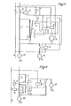
- the load shedding relay of FIG. 1 comprises a power detector ccnstituted by a bimetallic strip 1, this bimetallic strip being shunted by a resistor 2 which can be a resistance bridge in parallel. In series with resistor 2, the normally closed armature 3 of the remote control relay is mounted.
- the value of the shunt is such that the ratio between the resistance of the bimetallic strip and the shunt in parallel and the resistance of the bimetallic strip alone corresponds to the ratio between the set power of the load shedding in crisis period (minimum power) and that in normal period (power subscribed).
- the deformation of the bimetallic strip will therefore be a function of the ratio of the power consumed to the set power when the armature 3 is open and a function of a fraction of this ratio when the armature is closed, this fraction being equal to the resistance ratio of the bimetallic strip and shunt in parallel on resistance of the bimetallic strip.
- the deformation of the bimetallic strip is detected by an oscillating blade 4 which amplifies its deformations and which cooperates with elastic contacts of adjustable positions 5, 6, 7, 8 and 9 in the present case.
- Contact 5 is closed when the setpoint power is exceeded.
- Contact 6 is a reset contact when the power consumed falls to a fraction re-authorizing the recirculation of cut consumer devices after the relay has shed power, regardless of the set power.
- Contact 7 corresponds to the deformation of the bimetallic strip in the case where the power consumed exceeds the minimum setpoint power while the load shedding relay operates with the maximum load shedding setpoint power and contact 8 corresponds to the deformation of the bimetallic strip in the case where the power consumed corresponds to the value for establishing contact 7 increased by the nominal power of non-priority consumer devices and contact 9 is an additional contact closed when the intensity exceeds by a few percent the intensity closing the contact 5 and constituting a contact for controlling the trip device of the circuit breaker.
- a subscribed power of 9kw reduced to 3 kw in a crisis hour priority devices of nominal power 2kw, second priority devices of nominal power 8kw and non-priority devices having a nominal power of 4kw.
- the devices are immediately cut non-priority reils to avoid that the bimetallic strip of the circuit breaker which is now crossed by the totality of the current instead of being crossed by a third of the current, does not heat up and passes by inertia the point of tripping of the circuit breaker. This cut will bring down the power consumed but at most 4 kW, power of non-priority devices. If it is greater than 7 kw, situation detected by contact 8, it is therefore necessary to switch off the second priority devices.
- the load-shedding relay is allowed to operate normally with the load-shedding contact 5 which, when it is established, switches off non-priority devices or devices of second priority if the non-priority devices have already been switched off and the contact 6 which, when it is switched off, resets the second priority devices or non-priority devices if the second priority devices were already switched off.
- the electromagnetic circuit comprises a circuit breaker 10, the tripping coil 11 of which is controlled by the contact 9 and a remote control relay 12 which comprises, in addition to the armature 3 which cuts the shunt comprising the resistor 2, two armatures 13 and 14, the one of the pads is connected to the contacts 7 and 8 respectively, these plates closing their contacts when the relay is energized.
- This remote control relay is powered by a known type of remote-controlled contactor 15.
- the second pad of the armatures 13 and 14 is connected to the coil of the circuit breakers 16 and 17 respectively, these circuit breakers respectively controlling the supply of the non-priority devices 18 and of the second priority devices 19, the priority devices 20 being supplied directly by the phase .
- Relay 16 is a delayed relay on closing and relay 17 a delayed relay on opening, this delay being of the order of several seconds and fixed according to the inertia of the power detector 1 as will be explained below .
- the plates 13 and 14 and the relay coils 16 and 17 are connected the plates 22 of the relay 21 delayed on opening, the duration of this delay corresponding to the time required for the power detector 1 to take its position d balance after cutting the shunt.
- This relay is supplied by contact 7 because it only has to intervene if at least this contact is closed.
- the relays 16 and 17 are self-powered by the contact 6 and their armature 23 in the open position and they are powered by the closure of the contact 5 by their armature 23 in the closed position.
- the contact 5 For 9 kW the contact 5 is closed and it supplies the relays 16 and 17.
- the relay 17 being delayed on opening, the relay 16 opens first and cuts non-priority devices 18. Reducing the power consumed can reverse the movement of detector 1 after a delay due to the thermal inertia which is less than the delay of relay 17. Otherwise, relay 17 also opens and cuts second priority devices. If the consumption by the priority circuit remains too high, the contact 9 closes and the circuit breaker 10 trips. If on the other hand the consumption drops below 8 kw, the contact 6 which kept the relays 16 and 17 self-energized opens, which removes the power supply from the relays. The relay 17 closes and if the overall consumption remains below 8kw, the relay 16 also closes with a delay which takes into account the inertia of the power detector to react to the consumption of the devices 19 after the relay 17 closes.
- relay 12 If during operation and at any time the remote-controlled contactor closes, relay 12 is energized, it opens its armature 3 and closes its armatures 13 and 14. All of the consumption goes into bimetal 1. It exists at this moment three possibilities. The instantaneous consumption at the time of switching was more than 7 kW and the contacts 7 and 8 were closed; the closing of the frames 13 and 14 will open the relay 16 then, after a delay, the relay 17 unless the opening of the relay 16 has caused a sufficient reduction in the load. The instantaneous consumption at the time of consumption was between 3 and 7 kw and the contact 7 was closed, the closure of relay 12 will cause the closure of only relay 16 and the shutdown of non-priority devices 18.
- the relay 21 will open with a certain delay which is fixed to be sufficient to allow the bimetallic strip 1 to deform so that contact is established on contact 6, which will take place if the overall consumption is greater than 2 kw6. If it is less than 2 kw 6, the relay 21 opens, the relay 17 not supplied with power closes again, which authorizes an increase in consumption by the devices of second priority 1 9, but if the consumption then becomes greater than 3 kw, contact 5 closed reopens relay 17. If the overall consumption of priority and second priority devices 19 and 20 is less than 2kw6 during the delay in closing relay 16, it closes and authorizes the supply of non-priority devices 18.
- a load-shedding relay with power circuit breaker with remote-adjustable threshold which has the advantage of not cutting the shunt of the power detector is shown in Figure 2.
- the system with second priority devices has been eliminated. to keep only the priority 20 and non-priority 18 devices.
- the essential difference is that there are two sets of contacts 5, 6 - 5 ', 6' which correspond first to the detection of 9 and 8 kw and the seconds at, for example, 3 and 2.6 kw, these values can obviously be modified by adjusting the position of the contacts, by modifying the value of the shunt resistance 2, etc.
- the relay 12 is a rocker which selects the commissioning either of the contacts 5 and 6 when the allocated power is the maximum subscribed power, or of the contacts 5 ′, 6 ′ when the allocated power is the crisis power.
- Relay 24 is a closing delay relay, the armature of which closes the circuit breaker 10 supply circuit.
- the detector 1 is crossed by a fraction of the current consumed and in case of exceeding the set power, the load shedding is controlled by the contacts 5 and 6. If the armature 3 is open and the resistance 2 ′ being higher than the resistance 2, the current passing through the detector is higher than that passing through the detector 1 and it corresponds to the entire current consumed if 2 'does not exist. So will be the active detector which, for 3 kw with the figures above, will ensure contact on 5 '. and load shedding of non-priority devices.
Landscapes
- Engineering & Computer Science (AREA)
- Power Engineering (AREA)
- Supply And Distribution Of Alternating Current (AREA)
- Remote Monitoring And Control Of Power-Distribution Networks (AREA)
Applications Claiming Priority (2)
| Application Number | Priority Date | Filing Date | Title |
|---|---|---|---|
| FR8001607 | 1980-01-25 | ||
| FR8001607A FR2474777B1 (fr) | 1980-01-25 | 1980-01-25 | Perfectionnement aux relais de delestage |
Publications (2)
| Publication Number | Publication Date |
|---|---|
| EP0033273A2 true EP0033273A2 (de) | 1981-08-05 |
| EP0033273A3 EP0033273A3 (de) | 1981-08-19 |
Family
ID=9237864
Family Applications (1)
| Application Number | Title | Priority Date | Filing Date |
|---|---|---|---|
| EP81400089A Withdrawn EP0033273A3 (de) | 1980-01-25 | 1981-01-22 | Stromunterbrechungsrelais |
Country Status (4)
| Country | Link |
|---|---|
| US (1) | US4392064A (de) |
| EP (1) | EP0033273A3 (de) |
| CA (1) | CA1154858A (de) |
| FR (1) | FR2474777B1 (de) |
Cited By (2)
| Publication number | Priority date | Publication date | Assignee | Title |
|---|---|---|---|---|
| EP0040146A1 (de) * | 1980-05-14 | 1981-11-18 | Rosette Alberti | Leistungsschalter mit ferngesteuerter Tätigkeitsschwelle |
| FR2516303A1 (fr) * | 1981-11-06 | 1983-05-13 | Merlin Gerin | Disjoncteur de branchement a basse tension equipe d'un commutateur de calibre telecommande |
Families Citing this family (2)
| Publication number | Priority date | Publication date | Assignee | Title |
|---|---|---|---|---|
| US4472640A (en) * | 1983-02-16 | 1984-09-18 | Elmer Bayard W | Peak load limiting |
| CN103389655B (zh) * | 2013-07-25 | 2016-07-27 | 中国船舶重工集团公司第七二二研究所 | 一种远程断电装置和系统 |
Family Cites Families (8)
| Publication number | Priority date | Publication date | Assignee | Title |
|---|---|---|---|---|
| FR1147621A (fr) * | 1956-04-10 | 1957-11-27 | Bresson Faille Marchand Ets | Perfectionnement apporté aux disjoncteurs à calibres multiples par shunts incorporés |
| US3643160A (en) * | 1970-03-19 | 1972-02-15 | Westinghouse Electric Corp | Three-frequency relaying system |
| FR2147841B1 (de) * | 1971-08-02 | 1974-03-29 | Merlin Gerin | |
| US3894244A (en) * | 1973-10-03 | 1975-07-08 | Ross K Hill | Power limit and control system |
| DE2404234C2 (de) * | 1974-01-30 | 1983-02-03 | Licentia Patent-Verwaltungs-Gmbh, 6000 Frankfurt | Anordnung zur Lastverteilung in Niederspannungsnetzen |
| US4023043A (en) * | 1974-08-16 | 1977-05-10 | Megatherm Corporation | Computerized peak-shaving system for alleviating electric utility peak loads |
| US4152605A (en) * | 1977-10-03 | 1979-05-01 | Conde Hector O | Automatic load control system and method for a power distribution network |
| FR2464588A1 (fr) * | 1979-08-31 | 1981-03-06 | Alberti Rosette | Reseau de distribution electrique avec telereglage des disjoncteurs de puissance |
-
1980
- 1980-01-25 FR FR8001607A patent/FR2474777B1/fr not_active Expired
-
1981
- 1981-01-22 EP EP81400089A patent/EP0033273A3/de not_active Withdrawn
- 1981-01-23 CA CA000369153A patent/CA1154858A/fr not_active Expired
- 1981-01-26 US US06/228,087 patent/US4392064A/en not_active Expired - Fee Related
Cited By (3)
| Publication number | Priority date | Publication date | Assignee | Title |
|---|---|---|---|---|
| EP0040146A1 (de) * | 1980-05-14 | 1981-11-18 | Rosette Alberti | Leistungsschalter mit ferngesteuerter Tätigkeitsschwelle |
| FR2516303A1 (fr) * | 1981-11-06 | 1983-05-13 | Merlin Gerin | Disjoncteur de branchement a basse tension equipe d'un commutateur de calibre telecommande |
| EP0079270A1 (de) * | 1981-11-06 | 1983-05-18 | Merlin Gerin | Niederspannungsabzweigschalter mit einem ferngesteuerten Einstellschalter |
Also Published As
| Publication number | Publication date |
|---|---|
| CA1154858A (fr) | 1983-10-04 |
| FR2474777A1 (fr) | 1981-07-31 |
| US4392064A (en) | 1983-07-05 |
| FR2474777B1 (fr) | 1985-10-04 |
| EP0033273A3 (de) | 1981-08-19 |
Similar Documents
| Publication | Publication Date | Title |
|---|---|---|
| FR2637744A1 (fr) | Disjoncteur numerique avec parametres de declenchement pour moteur electrique | |
| FR2661588A1 (fr) | Circuit d'eclairage pour lampe a decharge pour vehicules. | |
| EP1225673B1 (de) | Elektrische Energieverteilungsvorrichtung, Anlage mit einer solchen Vorrichtung und Verfahren zum elektrischen Schutz | |
| EP0806781B1 (de) | Schaltung zur geschützten Versorgung einer elektrischen Last | |
| EP0224535B1 (de) | Statischer schalter oder schaltgerät zur geschützten versorgung einer last und ihrer leitung | |
| EP3694068B1 (de) | Statisches schaltsystem und system zur begrenzung eines gleichstroms | |
| EP1009004B1 (de) | Einrichtung zur Steuerung eines Elektromagneten, mit Erfassung von unbeabsichtigtem Bewegen des beweglichen Kerns eines Elektromagneten | |
| EP0033273A2 (de) | Stromunterbrechungsrelais | |
| EP0688080B1 (de) | Verwaltungsvorrichtung für elektrische Energieverteilungsanlage | |
| FR2482774A1 (fr) | Disjoncteur de puissance a seuil de fonctionnement telereglable | |
| FR2625861A1 (fr) | Dispositif photosensible de commutation, et ensemble et procede d'eclairage le comportant | |
| EP0424283A1 (de) | Steuervorrichtung für einen ferngesteuerten Schalter | |
| FR2733648A1 (fr) | Relais statique protege | |
| EP4016777B1 (de) | Stromschutzgerät einer elektrischen anlage mit wechselstrom | |
| EP0237444A1 (de) | Stromunterbrechungsrelais, insbesondere "zum Ausschalten bei spitzen Zeiten" | |
| EP0034979A1 (de) | Mit einem elektrischen Motor ausgerüsteter Treibstoffbrenner | |
| EP0330581B1 (de) | Verfahren und Vorrichtung zur Speisung einer Elektroinstallation und ihre Anwendung bei Lampen | |
| EP0192540A1 (de) | Zerhackerspeisung mit Schutz gegen sehr hohe Überlasten | |
| EP0031734A2 (de) | Verfahren und Vorrichtung zur Ausnützung eines Elektrizitätsversorgungsnetzes mit Fernsteuerung von Leistungsschaltern | |
| BE898516A (fr) | Montage de commande d'un organe de réglage électromagnétique à haute inductance pour machines textiles. | |
| BE407626A (de) | ||
| FR2622750A1 (fr) | Systeme de controle du fonctionnement d'un groupe electrogene | |
| BE567707A (de) | ||
| FR2538158A1 (fr) | Transformateur utilisable comme une source de fourniture continue et sans defaillance d'une tension alternative | |
| BE365236A (de) |
Legal Events
| Date | Code | Title | Description |
|---|---|---|---|
| PUAI | Public reference made under article 153(3) epc to a published international application that has entered the european phase |
Free format text: ORIGINAL CODE: 0009012 |
|
| PUAL | Search report despatched |
Free format text: ORIGINAL CODE: 0009013 |
|
| AK | Designated contracting states |
Designated state(s): AT BE CH DE GB IT LU NL SE |
|
| AK | Designated contracting states |
Designated state(s): AT BE CH DE GB IT LU NL SE |
|
| 17P | Request for examination filed |
Effective date: 19811028 |
|
| STAA | Information on the status of an ep patent application or granted ep patent |
Free format text: STATUS: THE APPLICATION HAS BEEN WITHDRAWN |
|
| 18W | Application withdrawn |
Withdrawal date: 19840223 |