EP0033281B1 - Vorrichtung zum Spritzen eines Wandbelages, insbesondere für eine Aushöhlung - Google Patents
Vorrichtung zum Spritzen eines Wandbelages, insbesondere für eine Aushöhlung Download PDFInfo
- Publication number
- EP0033281B1 EP0033281B1 EP81400115A EP81400115A EP0033281B1 EP 0033281 B1 EP0033281 B1 EP 0033281B1 EP 81400115 A EP81400115 A EP 81400115A EP 81400115 A EP81400115 A EP 81400115A EP 0033281 B1 EP0033281 B1 EP 0033281B1
- Authority
- EP
- European Patent Office
- Prior art keywords
- centrifugal wheel
- pipework
- filler
- whirling
- admission
- Prior art date
- Legal status (The legal status is an assumption and is not a legal conclusion. Google has not performed a legal analysis and makes no representation as to the accuracy of the status listed.)
- Expired
Links
Images

Classifications
-
- B—PERFORMING OPERATIONS; TRANSPORTING
- B05—SPRAYING OR ATOMISING IN GENERAL; APPLYING FLUENT MATERIALS TO SURFACES, IN GENERAL
- B05B—SPRAYING APPARATUS; ATOMISING APPARATUS; NOZZLES
- B05B3/00—Spraying or sprinkling apparatus with moving outlet elements or moving deflecting elements
- B05B3/02—Spraying or sprinkling apparatus with moving outlet elements or moving deflecting elements with rotating elements
- B05B3/10—Spraying or sprinkling apparatus with moving outlet elements or moving deflecting elements with rotating elements discharging over substantially the whole periphery of the rotating member
-
- E—FIXED CONSTRUCTIONS
- E21—EARTH OR ROCK DRILLING; MINING
- E21B—EARTH OR ROCK DRILLING; OBTAINING OIL, GAS, WATER, SOLUBLE OR MELTABLE MATERIALS OR A SLURRY OF MINERALS FROM WELLS
- E21B33/00—Sealing or packing boreholes or wells
- E21B33/10—Sealing or packing boreholes or wells in the borehole
- E21B33/13—Methods or devices for cementing, for plugging holes, crevices or the like
- E21B33/138—Plastering the borehole wall; Injecting into the formation
-
- E—FIXED CONSTRUCTIONS
- E21—EARTH OR ROCK DRILLING; MINING
- E21B—EARTH OR ROCK DRILLING; OBTAINING OIL, GAS, WATER, SOLUBLE OR MELTABLE MATERIALS OR A SLURRY OF MINERALS FROM WELLS
- E21B41/00—Equipment or details not covered by groups E21B15/00 - E21B40/00
- E21B41/0078—Nozzles used in boreholes
-
- E—FIXED CONSTRUCTIONS
- E21—EARTH OR ROCK DRILLING; MINING
- E21D—SHAFTS; TUNNELS; GALLERIES; LARGE UNDERGROUND CHAMBERS
- E21D11/00—Lining tunnels, galleries or other underground cavities, e.g. large underground chambers; Linings therefor; Making such linings in situ, e.g. by assembling
-
- E—FIXED CONSTRUCTIONS
- E21—EARTH OR ROCK DRILLING; MINING
- E21D—SHAFTS; TUNNELS; GALLERIES; LARGE UNDERGROUND CHAMBERS
- E21D5/00—Lining shafts; Linings therefor
-
- Y—GENERAL TAGGING OF NEW TECHNOLOGICAL DEVELOPMENTS; GENERAL TAGGING OF CROSS-SECTIONAL TECHNOLOGIES SPANNING OVER SEVERAL SECTIONS OF THE IPC; TECHNICAL SUBJECTS COVERED BY FORMER USPC CROSS-REFERENCE ART COLLECTIONS [XRACs] AND DIGESTS
- Y10—TECHNICAL SUBJECTS COVERED BY FORMER USPC
- Y10S—TECHNICAL SUBJECTS COVERED BY FORMER USPC CROSS-REFERENCE ART COLLECTIONS [XRACs] AND DIGESTS
- Y10S118/00—Coating apparatus
- Y10S118/10—Pipe and tube inside
Definitions
- the subject of the invention is a device for simultaneously projecting a liquid or pasty product and a pulverulent, granular or fibrous filler to produce a reinforced plastic wall covering or coating, in which the product is pumped to a centrifugal projection with central feed.
- the published German patent application number 2808903 describes a device intended to project two components of a plastic material against the interior surface of a pipe.
- This device essentially comprises a shaft at one end of which is fixed in rotation a centrifugal disc with a convex or conical face opposite which open two parallel pipes, arranged symmetrically with the shaft in the same diametral plane.
- the two components are sent under pressure and they meet in the same annular zone the centrifugal disc which projects them against the interior surface of the pipeline.
- This device is useful when it comes to projecting components which are not very different and above all, which support or require to be mixed at the same time of their projection.
- the coating can be a mortar, plaster or a resin setting on the projected surface.
- a pulverulent, grainy or fibrous filler in particular a glass fiber filler, is sprayed onto this first layer.
- a coating is commonly used for the sealing of rock walls and to prevent falls of granular or pulverulent materials.
- aminoplast resin sprayed with shredded glass fibers Of course, the applications of the invention will not be limited to this particular application, nor to the products mentioned.
- the known devices used for the application of this process require the presence, in the immediate vicinity, of an operator.
- the object of the invention is to provide a new device which is easier to use than known devices, which can be used conveniently in excavations, even if they are inaccessible or difficult for a man to access, and therefore can be operated remotely and operate safely, which requires no risk of blockage.
- the turnstile and the centrifugal wheel are rotated on the same shaft.
- the means of supplying the load is a pneumatic transport pipe which opens into the axis of the centrifugal wheel on the side opposite the turnstile and the centrifugal wheel is conical with its apex directed towards the discharge end of this pipe.
- the device of the invention comprises means of support in translation on the walls, which means advantageously serve as centering means and cause that the axis of the turnstile and the direction of translation are parallel.
- the speed of coating of the constituent material will be improved.
- the load by orienting the device so that the centrifugal wheel is upstream aerating relative to the turnstile.
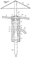
- a housing 1 consists of a sealed rolling bearing with two ball bearings 2 and 3, provided in the vicinity of its ends, for a shaft 4 which passes right through it.
- the shaft 4 carries a hub 13 traversed by tubes 6 at regular angular distances, for example two tubes at 180 ° from one another, substantially radial from the hub, then slightly bent , open at their ends remote from the axis and communicating on the axis with a central channel 7 provided in the axis of the shaft 4 and extending to an annular groove 8 of the shaft 4 delimiting an annular chamber 9 between the shaft and the housing.
- a transverse channel 10 puts the central channel 7 in communication with the annular chamber 8, into which opens a passage channel of the housing 1, itself connectable to a supply pipe 12.
- the assembly described hitherto constitutes a turnstile 20 with central feed for the projection of the product, which can be brought under pressure via the pipe 12.
- the hub 13 carries, on a side opposite the shaft 4, a short shaft 14 of axis extending the axis of the shaft and carrying at its end a wheel 15 in the form of an obtuse cone 16 whose apex 17 is directed opposite the turnstile.
- a pipe 18 opens into the axis of the wheel 15 near the apex 17 of the cone 16.
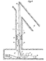
- the pipe 18 is a pipe for pneumatic transport of glass fiber supply previously shredded, or other suitable material that can be transported pneumatically, from a storage hopper 19 (FIG. 3) by suction in a pipe 21 by means of an ejector 22 supplied with compressed air by a pipe 23.
- the shaft 4 is shaped as a cone 24 for attachment to a motor 38 constituted by a rotary perforator 25 with compressed air supplied with compressed air by a pipe 37.
- a central tubular element 27 coaxial with the turnstile 20 is connected to the frame 26 and is arranged so as to release the projection planes of the turnstile and of the centrifugal wheel.
- FIG 1 the central tubular member opposite the housing and the punch relative to the turnstile, but it could just as easily surround the housing and the punch, provided that the projection planes are clear.
- the central tubular element 27 carries three skis 28 mounted on springs 29 to center the entire device in an excavation.
- the tubular element 27 ends in a cone and a ring 30 for coupling the entire device to a hauling cable 31.
- the frame 26 also carries a guide slide 32 for the return strand 33 of the hauling cable 31.
- FIG 3 there is shown an application to the remote spraying of a resin reinforced with glass fibers to consolidate the walls of a borehole 40 of 600 mm in coal ground and simultaneously prevent oxidation of the solid in coal areas.
- the purpose of drilling the borehole 40 was to improve the ventilation in a tracing track 41 from a gallery 42 of a neighborhood in operation and to serve as an emergency exit.
- a winch 43 was installed in the tracing 41 for an endless cable 34, 33, 31 returned by a pulley 35 installed in the gallery 42.
- the device of the invention is hauled into the borehole , thanks to the ring 30.
- the turnstile is supplied with resin from a pumping station 36 through the pipe 12 and the centrifugal wheel is supplied with shredded glass fibers as has already been explained.
- the survey also includes one or more compressed air pipes 23, 37, which have not been shown in FIG. 3 for the simplification of the drawings, but which are of the usual type in mines.
Landscapes
- Engineering & Computer Science (AREA)
- Mining & Mineral Resources (AREA)
- Life Sciences & Earth Sciences (AREA)
- Geology (AREA)
- General Life Sciences & Earth Sciences (AREA)
- Geochemistry & Mineralogy (AREA)
- Physics & Mathematics (AREA)
- Environmental & Geological Engineering (AREA)
- Fluid Mechanics (AREA)
- Civil Engineering (AREA)
- Architecture (AREA)
- Structural Engineering (AREA)
- Mechanical Engineering (AREA)
- Nozzles (AREA)
- Earth Drilling (AREA)
- Coating Apparatus (AREA)
- Lining And Supports For Tunnels (AREA)
- Bulkheads Adapted To Foundation Construction (AREA)
- Details Of Measuring And Other Instruments (AREA)
- Magnetic Resonance Imaging Apparatus (AREA)
- Light Guides In General And Applications Therefor (AREA)
Claims (10)
Priority Applications (1)
| Application Number | Priority Date | Filing Date | Title |
|---|---|---|---|
| AT81400115T ATE5912T1 (de) | 1980-01-29 | 1981-01-27 | Vorrichtung zum spritzen eines wandbelages, insbesondere fuer eine aushoehlung. |
Applications Claiming Priority (2)
| Application Number | Priority Date | Filing Date | Title |
|---|---|---|---|
| FR8001861A FR2474351B1 (fr) | 1980-01-29 | 1980-01-29 | Dispositif de projection d'enduit mural, notamment pour excavation |
| FR8001861 | 1980-01-29 |
Publications (2)
| Publication Number | Publication Date |
|---|---|
| EP0033281A1 EP0033281A1 (de) | 1981-08-05 |
| EP0033281B1 true EP0033281B1 (de) | 1984-01-18 |
Family
ID=9237981
Family Applications (1)
| Application Number | Title | Priority Date | Filing Date |
|---|---|---|---|
| EP81400115A Expired EP0033281B1 (de) | 1980-01-29 | 1981-01-27 | Vorrichtung zum Spritzen eines Wandbelages, insbesondere für eine Aushöhlung |
Country Status (8)
| Country | Link |
|---|---|
| US (1) | US4377127A (de) |
| EP (1) | EP0033281B1 (de) |
| JP (1) | JPS56121655A (de) |
| AT (1) | ATE5912T1 (de) |
| BR (1) | BR8100473A (de) |
| DE (1) | DE3161903D1 (de) |
| FR (1) | FR2474351B1 (de) |
| SU (1) | SU1242001A3 (de) |
Families Citing this family (8)
| Publication number | Priority date | Publication date | Assignee | Title |
|---|---|---|---|---|
| JPS60248256A (ja) * | 1984-05-25 | 1985-12-07 | Shinichi Matsuda | パイプのライニング装置 |
| US4704985A (en) * | 1986-05-30 | 1987-11-10 | Nordson Corporation | Spray gun mover |
| US5092265A (en) * | 1989-10-23 | 1992-03-03 | Hughes J David | Apparatus for applying resin coatings |
| DE19500470A1 (de) * | 1995-01-10 | 1996-07-11 | Huckfeldt & Thorlichen | Verfahren und Vorrichtung zum Herstellen von Wursthüllen sowie danach hergestellte Wursthülle |
| GB2503203A (en) * | 2012-05-02 | 2013-12-25 | Michael Pritchard | Wellbore lining using a directional nozzle |
| CN106193548B (zh) * | 2016-07-07 | 2019-01-29 | 上海筱臻金属制品有限公司 | 粘稠流体材料喷涂机 |
| WO2019070297A1 (en) * | 2017-10-06 | 2019-04-11 | Halliburton Energy Services, Inc. | DEVIATION ELEMENT FOR CEMENTING A CUT-OFF WINDOW IN A TUBING |
| CN120331819B (zh) * | 2025-06-19 | 2025-08-19 | 长春黄金研究院有限公司 | 大直径双向v字形贯通孔巷道顶板淋水防治方法 |
Citations (6)
| Publication number | Priority date | Publication date | Assignee | Title |
|---|---|---|---|---|
| US2297099A (en) * | 1940-02-08 | 1942-09-29 | John M Crom | Tunnel lining machine |
| FR1084168A (fr) * | 1953-01-10 | 1955-01-17 | Atomiseur | |
| US3810441A (en) * | 1968-12-12 | 1974-05-14 | Raymond Int Inc | Lining machine |
| FR2371627A1 (fr) * | 1976-11-22 | 1978-06-16 | Siargas | Procede pour realiser des joints etanches dans une canalisation enterree. dispositif pour le mettre en oeuvre |
| FR2371242A1 (fr) * | 1976-11-22 | 1978-06-16 | Siargas Spa | Procede et dispositif pour la formation de revetements etanches a l'interieur de conduites destinees au transport de fluides |
| DE2808903A1 (de) * | 1978-03-02 | 1979-09-06 | Karl Reinhard Zeiss | Verfahren zum aufbringen eines homogenen kunststoffmantels auf die innenwandung von rohren und vorrichtung zur durchfuehrung des verfahrens |
Family Cites Families (7)
| Publication number | Priority date | Publication date | Assignee | Title |
|---|---|---|---|---|
| DE437062C (de) | 1926-11-13 | Escher Wyss Maschf Ag | Dampf- oder Gasturbine mit Leitscheiben, insbesondere fuer hohe Druecke und Waermegrade | |
| US1971535A (en) * | 1931-12-08 | 1934-08-28 | Albert G Perkins | Apparatus for coating pipe |
| US2168917A (en) * | 1937-04-03 | 1939-08-08 | Albert G Perkins | Apparatus for coating pipes and the like |
| US2922583A (en) * | 1959-04-06 | 1960-01-26 | Perkins Pipe Linings Inc | Pipe lining machine |
| US3108348A (en) * | 1959-07-31 | 1963-10-29 | Raymond Int Inc | Lining of pipes including lining machine with belt drive trowels |
| CH437062A (de) * | 1965-09-09 | 1967-05-31 | Lechler Bautenschutzchemie Kg | Gerät zum Beschichten der Innenwand von Hohlräumen, insbesondere von Rohrinnenwänden |
| US3690560A (en) * | 1971-04-22 | 1972-09-12 | John A Boyd | Chute sanitizer and fire extinguisher |
-
1980
- 1980-01-29 FR FR8001861A patent/FR2474351B1/fr not_active Expired
-
1981
- 1981-01-27 DE DE8181400115T patent/DE3161903D1/de not_active Expired
- 1981-01-27 AT AT81400115T patent/ATE5912T1/de not_active IP Right Cessation
- 1981-01-27 EP EP81400115A patent/EP0033281B1/de not_active Expired
- 1981-01-28 BR BR8100473A patent/BR8100473A/pt unknown
- 1981-01-28 SU SU813245352A patent/SU1242001A3/ru active
- 1981-01-28 US US06/229,265 patent/US4377127A/en not_active Expired - Fee Related
- 1981-01-28 JP JP1032381A patent/JPS56121655A/ja active Pending
Patent Citations (6)
| Publication number | Priority date | Publication date | Assignee | Title |
|---|---|---|---|---|
| US2297099A (en) * | 1940-02-08 | 1942-09-29 | John M Crom | Tunnel lining machine |
| FR1084168A (fr) * | 1953-01-10 | 1955-01-17 | Atomiseur | |
| US3810441A (en) * | 1968-12-12 | 1974-05-14 | Raymond Int Inc | Lining machine |
| FR2371627A1 (fr) * | 1976-11-22 | 1978-06-16 | Siargas | Procede pour realiser des joints etanches dans une canalisation enterree. dispositif pour le mettre en oeuvre |
| FR2371242A1 (fr) * | 1976-11-22 | 1978-06-16 | Siargas Spa | Procede et dispositif pour la formation de revetements etanches a l'interieur de conduites destinees au transport de fluides |
| DE2808903A1 (de) * | 1978-03-02 | 1979-09-06 | Karl Reinhard Zeiss | Verfahren zum aufbringen eines homogenen kunststoffmantels auf die innenwandung von rohren und vorrichtung zur durchfuehrung des verfahrens |
Also Published As
| Publication number | Publication date |
|---|---|
| EP0033281A1 (de) | 1981-08-05 |
| US4377127A (en) | 1983-03-22 |
| FR2474351B1 (fr) | 1985-05-31 |
| JPS56121655A (en) | 1981-09-24 |
| SU1242001A3 (ru) | 1986-06-30 |
| DE3161903D1 (en) | 1984-02-23 |
| ATE5912T1 (de) | 1984-02-15 |
| BR8100473A (pt) | 1981-08-18 |
| FR2474351A1 (fr) | 1981-07-31 |
Similar Documents
| Publication | Publication Date | Title |
|---|---|---|
| EP0033281B1 (de) | Vorrichtung zum Spritzen eines Wandbelages, insbesondere für eine Aushöhlung | |
| US5096002A (en) | Method and apparatus for enlarging an underground path | |
| US10900286B2 (en) | Apparatus and method for drilling generally horizontal underground boreholes | |
| JPS62100321A (ja) | 粒状材料の運搬システム | |
| US20150376953A1 (en) | Vertical-screw-auger conveyer feeder | |
| CN102247011A (zh) | 将烟草加工业的杆状物品从储藏匣运送到输送线中的装置和方法 | |
| JPS5814920B2 (ja) | シ−ルドトンネル掘進装置 | |
| US3428363A (en) | Gallery driving machine | |
| US3905430A (en) | Apparatus for raise drilling | |
| JP2675275B2 (ja) | 湿潤粘着性材料を空気搬送し噴射するための装置 | |
| US5257691A (en) | Arrangement for transferring castable material without pipes from a feeding means to a destination | |
| FR2513604A1 (fr) | Procede et dispositif pour acheminer, de preference en continu, des matieres allant de l'etat pulverulent a l'etat de grains grossiers | |
| FR2513309A1 (fr) | Machine a bouclier pour forer des tunnels | |
| US2749102A (en) | Auger drill head | |
| KR102639984B1 (ko) | 분체 또는 입상체의 장거리 수송이 가능한 공기압 이송 장치 | |
| CN102713151A (zh) | 包括流体进给的用于边坡开采的部件和设备 | |
| US2290809A (en) | Dust spraying apparatus | |
| JPH03158312A (ja) | 垂直式輸送装置 | |
| FI109928B (fi) | Menetelmä ja laite suolalietteen levittämiseksi | |
| CN111620053A (zh) | 矿用螺杆排渣器 | |
| EP0051544A1 (de) | Anlage mit einem oder mehreren Aufnahmeköpfen für lose schlammartige, körnige, feuchte oder nichtfeuchte Massen | |
| SU1678719A1 (ru) | Метательное устройство | |
| SU1015841A1 (ru) | Центробежный метатель дл сыпучих материалов | |
| CN207920613U (zh) | 一种低功耗地铁盾构施工运料机 | |
| CH318676A (fr) | Appareil destiné au transport de matières pulvérulentes |
Legal Events
| Date | Code | Title | Description |
|---|---|---|---|
| PUAI | Public reference made under article 153(3) epc to a published international application that has entered the european phase |
Free format text: ORIGINAL CODE: 0009012 |
|
| AK | Designated contracting states |
Designated state(s): AT BE DE GB IT LU |
|
| ITCL | It: translation for ep claims filed |
Representative=s name: BARZANO' E ZANARDO MILANO S.P.A. |
|
| TCAT | At: translation of patent claims filed | ||
| 17P | Request for examination filed |
Effective date: 19811008 |
|
| DET | De: translation of patent claims | ||
| ITF | It: translation for a ep patent filed | ||
| GRAA | (expected) grant |
Free format text: ORIGINAL CODE: 0009210 |
|
| AK | Designated contracting states |
Designated state(s): AT BE DE GB IT LU |
|
| PGFP | Annual fee paid to national office [announced via postgrant information from national office to epo] |
Ref country code: LU Payment date: 19840118 Year of fee payment: 4 |
|
| REF | Corresponds to: |
Ref document number: 5912 Country of ref document: AT Date of ref document: 19840215 Kind code of ref document: T |
|
| PG25 | Lapsed in a contracting state [announced via postgrant information from national office to epo] |
Ref country code: LU Free format text: LAPSE BECAUSE OF NON-PAYMENT OF DUE FEES Effective date: 19840131 |
|
| REF | Corresponds to: |
Ref document number: 3161903 Country of ref document: DE Date of ref document: 19840223 |
|
| PLBE | No opposition filed within time limit |
Free format text: ORIGINAL CODE: 0009261 |
|
| STAA | Information on the status of an ep patent application or granted ep patent |
Free format text: STATUS: NO OPPOSITION FILED WITHIN TIME LIMIT |
|
| 26N | No opposition filed | ||
| PGFP | Annual fee paid to national office [announced via postgrant information from national office to epo] |
Ref country code: AT Payment date: 19881222 Year of fee payment: 9 |
|
| PGFP | Annual fee paid to national office [announced via postgrant information from national office to epo] |
Ref country code: GB Payment date: 19890127 Year of fee payment: 9 |
|
| ITTA | It: last paid annual fee | ||
| PGFP | Annual fee paid to national office [announced via postgrant information from national office to epo] |
Ref country code: BE Payment date: 19890131 Year of fee payment: 9 |
|
| PG25 | Lapsed in a contracting state [announced via postgrant information from national office to epo] |
Ref country code: GB Effective date: 19900127 Ref country code: AT Effective date: 19900127 |
|
| PG25 | Lapsed in a contracting state [announced via postgrant information from national office to epo] |
Ref country code: BE Effective date: 19900131 |
|
| BERE | Be: lapsed |
Owner name: HOUILLERES DU BASSIN DE LORRAINE (ETABLISSEMENT P Effective date: 19900131 |
|
| GBPC | Gb: european patent ceased through non-payment of renewal fee | ||
| PGFP | Annual fee paid to national office [announced via postgrant information from national office to epo] |
Ref country code: DE Payment date: 19910327 Year of fee payment: 11 |
|
| PG25 | Lapsed in a contracting state [announced via postgrant information from national office to epo] |
Ref country code: DE Effective date: 19921001 |