EP0033304A1 - Vorrichtung für tragbare Schlagwerkzeuge - Google Patents
Vorrichtung für tragbare Schlagwerkzeuge Download PDFInfo
- Publication number
- EP0033304A1 EP0033304A1 EP81850005A EP81850005A EP0033304A1 EP 0033304 A1 EP0033304 A1 EP 0033304A1 EP 81850005 A EP81850005 A EP 81850005A EP 81850005 A EP81850005 A EP 81850005A EP 0033304 A1 EP0033304 A1 EP 0033304A1
- Authority
- EP
- European Patent Office
- Prior art keywords
- spring
- axle
- handles
- machine housing
- handle
- Prior art date
- Legal status (The legal status is an assumption and is not a legal conclusion. Google has not performed a legal analysis and makes no representation as to the accuracy of the status listed.)
- Withdrawn
Links
- 238000013016 damping Methods 0.000 claims description 3
- 230000006835 compression Effects 0.000 abstract 1
- 238000007906 compression Methods 0.000 abstract 1
- 238000004904 shortening Methods 0.000 abstract 1
- 238000002485 combustion reaction Methods 0.000 description 3
- 238000005553 drilling Methods 0.000 description 2
- 239000013013 elastic material Substances 0.000 description 1
- 229920001971 elastomer Polymers 0.000 description 1
- 229920002635 polyurethane Polymers 0.000 description 1
- 239000004814 polyurethane Substances 0.000 description 1
- 239000011435 rock Substances 0.000 description 1
Images

Classifications
-
- B—PERFORMING OPERATIONS; TRANSPORTING
- B25—HAND TOOLS; PORTABLE POWER-DRIVEN TOOLS; MANIPULATORS
- B25D—PERCUSSIVE TOOLS
- B25D17/00—Details of, or accessories for, portable power-driven percussive tools
- B25D17/04—Handles; Handle mountings
- B25D17/043—Handles resiliently mounted relative to the hammer housing
Definitions
- the present invention relates to a device for hand-held hammer machines for damping of vibrations transferred to the handles of the machine.
- the object of the present invention is to considerably damp the vibrations transferred from the machine housing to the handles. This is achieved by at least one spring being arranged such relative to the handles and the machine housing that the spring is compressed when the handles are pressed down and at the same time the moment arm of the spring force relative to the axis of rotation of the handle means is shortened in such a way that the moment of the spring force about this axis of rotation is substantially constant over the major part of the range of movement of the handles.
- fig. 1 shows a combined drilling and breaking machine in which the invention is used.
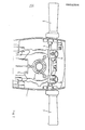
- Fig. 2 shows a part of the machine from behind with certain parts removed to show the invention.
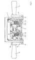
- Fig. 3 shows a corresponding view from above.
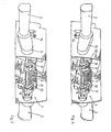
- Fig. 4 shows a perspective view from behind with the handles in one angular position.
- Fig. 5 shows a corresponding view with the handles in another angular position.
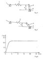
- Figs. 6 and 7 show schematically the operation of the invention.
- Fig. 8 shows how the force by which the handles are pressed down vary as a function of the downpressing of the handles.
- the machine shown in fig. 1 is a combined rock drilling and breaking machine which comprises a machine housing 1.
- a combustion engine is mounted in the machine housing in the usual way.
- the combustion chamber of the engine is situated between an engine piston connected to a crank shaft and the hammer piston of the machine. Since the driving of the hammer piston is not essential to the present invention other means , e.g. compressed air, could be incorporated for the driving of the hammer piston instead of the combustion engine.
- the machine is at its lower end provided with a tool, e.g. a drill rod 3.
- the machine is furthermore provided with a handle means, incorporating two handles 2, which is pivotally journalled in the machine housing 1.
- the machine is furthermore provided with a further handle 7 for more precise sideways control of the machine for certain types of operation, e.g. stamping.
- These handles are preferably made of an elastic material, e.g. polyurethane, in order to obtain good damping of high frequency vibrations.
- the upper part of the machine housing 1 is shown with certain parts removed to show a preferred embodiment of the invention.
- the upper part of the machine housing 1 comprises the crank housing 4 and a transverse axle 5 which is rotatably journalled in the machine housing.
- the axle 5 is by means of arms 13 connected with the handles 2.
- the axle 5 is furthermore provided with actuation means 6 in which short axles 8 are rotatably journalled.
- the arms 13 and the actuation means 6 are connected with the axle 5 by means of pins 14 or in another suitable way.
- Two helical springs 11 are supported at one end by cup- shaped support means 12 on the machine housing 1 and at the other end by nuts 10. If the machine is driven by compressed air springs 11 could be replaced by air springs.
- Nuts 10 are by means of adjustment screws connected with the short axles 8.
- Handles 2 are provided with pins 16 which cooperate with recesses 15 in the machine housing 1 in order to restrict the range of movement of the handles 2.
- Figs. 6 and 7 show schematically the operation of the vibration damper.
- Fig. 6 shows the position of the actuation means 6 when the handles 2 are not loaded.
- fig. 7 the actuation means 6 is shown in the position it takes when the handles 2 are near their lower limit position. In this position spring 11 has been compressed substantially so that the spring force has increased substantially.
- the moment arm A of the spring force relative to the axis 5 has been shortened. This occurs in such a way that the moment of the spring force about the axis 5 remains substantially constant over the major part of the range of movement of the handles 2.
- fig. 8 which shows how the feed force F applied against the handles 2 varies with the downpressing d in a tested case.
- the substantially constant force F which is obtained after a certain downpressing of the handles 2 can be changed by means of the adjustment screws 9.
- the machine housing 1 can oscillate in the working direction of the tool 3 without these vibrations being transferred to any substantial degree to the handles 2 and the machine operator.
Landscapes
- Engineering & Computer Science (AREA)
- Mechanical Engineering (AREA)
- Percussive Tools And Related Accessories (AREA)
- Vibration Prevention Devices (AREA)
- Portable Nailing Machines And Staplers (AREA)
Applications Claiming Priority (2)
| Application Number | Priority Date | Filing Date | Title |
|---|---|---|---|
| SE8000556A SE420058B (sv) | 1980-01-24 | 1980-01-24 | Svengningsdempande anordning vid handhallna slaende maskiner |
| SE8000556 | 1980-01-24 |
Publications (1)
| Publication Number | Publication Date |
|---|---|
| EP0033304A1 true EP0033304A1 (de) | 1981-08-05 |
Family
ID=20340052
Family Applications (1)
| Application Number | Title | Priority Date | Filing Date |
|---|---|---|---|
| EP81850005A Withdrawn EP0033304A1 (de) | 1980-01-24 | 1981-01-12 | Vorrichtung für tragbare Schlagwerkzeuge |
Country Status (3)
| Country | Link |
|---|---|
| EP (1) | EP0033304A1 (de) |
| JP (1) | JPS56107890A (de) |
| SE (1) | SE420058B (de) |
Cited By (14)
| Publication number | Priority date | Publication date | Assignee | Title |
|---|---|---|---|---|
| EP0115241A1 (de) * | 1983-02-03 | 1984-08-08 | MACO-MEUDON Société dite : | Schlagwerkzeug mit schwingenden Handgriffen |
| EP0194347A1 (de) * | 1984-12-24 | 1986-09-17 | Wacker-Werke GmbH & Co. KG | Gefederte Anbringung einer die Haltegriffe tragenden Schutzhaube an einem Schlagwerkzeug |
| GB2237528A (en) * | 1989-10-31 | 1991-05-08 | Breakers As | Vibration-damped hydraulic hammer |
| EP1529602A2 (de) | 2003-11-04 | 2005-05-11 | BLACK & DECKER INC. | Schwingungsdämpfungsvorrichtung für ein Elektrowerkzeug und Elektrowerkzeug mit einer solchen Vorrichtung |
| EP1529603A3 (de) * | 2003-11-04 | 2006-06-07 | BLACK & DECKER INC. | Schwingungsdämpfungsvorrichtung für ein Elektrowerkzeug und Elektrowerkzeug mit einer solchen Vorrichtung |
| EP1800804A2 (de) | 2005-12-23 | 2007-06-27 | HILTI Aktiengesellschaft | Handwerkzeuggerät mit gefederter Griffaufhängung |
| US7320369B2 (en) | 2003-11-04 | 2008-01-22 | Black & Decker Inc. | Vibration reduction apparatus for power tool and power tool incorporating such apparatus |
| US7322428B2 (en) | 2004-06-04 | 2008-01-29 | Black & Decker Inc. | Vibration reduction apparatus for power tool and power tool incorporating such apparatus |
| US7886838B2 (en) | 2008-03-18 | 2011-02-15 | Black & Decker Inc. | Hammer |
| US7987921B2 (en) | 2008-03-18 | 2011-08-02 | Black & Decker Inc. | Hammer |
| US10814468B2 (en) | 2017-10-20 | 2020-10-27 | Milwaukee Electric Tool Corporation | Percussion tool |
| US10926393B2 (en) | 2018-01-26 | 2021-02-23 | Milwaukee Electric Tool Corporation | Percussion tool |
| CN113905850A (zh) * | 2019-07-18 | 2022-01-07 | 喜利得股份公司 | 手持式电动工具 |
| DE102025103229A1 (de) * | 2025-01-29 | 2026-07-30 | Robert Bosch Gesellschaft mit beschränkter Haftung | Abbruchhammer mit zwei seitlichen Handgriffen |
Citations (2)
| Publication number | Priority date | Publication date | Assignee | Title |
|---|---|---|---|---|
| US1358486A (en) * | 1920-04-24 | 1920-11-09 | Ingersoll Rand Co | Handle for percussive tools |
| AT122752B (de) * | 1930-01-10 | 1931-05-11 | Ernst Ing Elster | Abfederung der Haltevorrichtung von Werzeugen mit hin und her gehender Arbeitsbewegung. |
-
1980
- 1980-01-24 SE SE8000556A patent/SE420058B/sv not_active IP Right Cessation
-
1981
- 1981-01-12 EP EP81850005A patent/EP0033304A1/de not_active Withdrawn
- 1981-01-23 JP JP806481A patent/JPS56107890A/ja active Pending
Patent Citations (2)
| Publication number | Priority date | Publication date | Assignee | Title |
|---|---|---|---|---|
| US1358486A (en) * | 1920-04-24 | 1920-11-09 | Ingersoll Rand Co | Handle for percussive tools |
| AT122752B (de) * | 1930-01-10 | 1931-05-11 | Ernst Ing Elster | Abfederung der Haltevorrichtung von Werzeugen mit hin und her gehender Arbeitsbewegung. |
Cited By (27)
| Publication number | Priority date | Publication date | Assignee | Title |
|---|---|---|---|---|
| EP0115241A1 (de) * | 1983-02-03 | 1984-08-08 | MACO-MEUDON Société dite : | Schlagwerkzeug mit schwingenden Handgriffen |
| EP0194347A1 (de) * | 1984-12-24 | 1986-09-17 | Wacker-Werke GmbH & Co. KG | Gefederte Anbringung einer die Haltegriffe tragenden Schutzhaube an einem Schlagwerkzeug |
| GB2237528A (en) * | 1989-10-31 | 1991-05-08 | Breakers As | Vibration-damped hydraulic hammer |
| US7320369B2 (en) | 2003-11-04 | 2008-01-22 | Black & Decker Inc. | Vibration reduction apparatus for power tool and power tool incorporating such apparatus |
| EP1529603A3 (de) * | 2003-11-04 | 2006-06-07 | BLACK & DECKER INC. | Schwingungsdämpfungsvorrichtung für ein Elektrowerkzeug und Elektrowerkzeug mit einer solchen Vorrichtung |
| US7472760B2 (en) | 2003-11-04 | 2009-01-06 | Black & Decker Inc. | Vibration reduction apparatus for power tool and power tool incorporating such apparatus |
| US7762348B2 (en) | 2003-11-04 | 2010-07-27 | Black & Decker Inc. | Vibration reduction apparatus for power tool and power tool incorporating such apparatus |
| EP1529602A2 (de) | 2003-11-04 | 2005-05-11 | BLACK & DECKER INC. | Schwingungsdämpfungsvorrichtung für ein Elektrowerkzeug und Elektrowerkzeug mit einer solchen Vorrichtung |
| US7322428B2 (en) | 2004-06-04 | 2008-01-29 | Black & Decker Inc. | Vibration reduction apparatus for power tool and power tool incorporating such apparatus |
| EP1800804A2 (de) | 2005-12-23 | 2007-06-27 | HILTI Aktiengesellschaft | Handwerkzeuggerät mit gefederter Griffaufhängung |
| US8342260B2 (en) | 2005-12-23 | 2013-01-01 | Hilti Aktiengesellschaft | Hand-held power tool with spring-loaded handle suspension |
| EP1800804A3 (de) * | 2005-12-23 | 2008-09-10 | HILTI Aktiengesellschaft | Handwerkzeuggerät mit gefederter Griffaufhängung |
| CN1986167B (zh) * | 2005-12-23 | 2010-12-08 | 希尔蒂股份公司 | 具有减振的手柄悬挂装置的手工工具机 |
| US7886838B2 (en) | 2008-03-18 | 2011-02-15 | Black & Decker Inc. | Hammer |
| US7987921B2 (en) | 2008-03-18 | 2011-08-02 | Black & Decker Inc. | Hammer |
| US11633843B2 (en) | 2017-10-20 | 2023-04-25 | Milwaukee Electric Tool Corporation | Percussion tool |
| US10814468B2 (en) | 2017-10-20 | 2020-10-27 | Milwaukee Electric Tool Corporation | Percussion tool |
| US11865687B2 (en) | 2018-01-26 | 2024-01-09 | Milwaukee Electric Tool Corporation | Percussion tool |
| US11141850B2 (en) | 2018-01-26 | 2021-10-12 | Milwaukee Electric Tool Corporation | Percussion tool |
| US11203105B2 (en) | 2018-01-26 | 2021-12-21 | Milwaukee Electric Tool Corporation | Percussion tool |
| US11059155B2 (en) | 2018-01-26 | 2021-07-13 | Milwaukee Electric Tool Corporation | Percussion tool |
| US11759935B2 (en) | 2018-01-26 | 2023-09-19 | Milwaukee Electric Tool Corporation | Percussion tool |
| US10926393B2 (en) | 2018-01-26 | 2021-02-23 | Milwaukee Electric Tool Corporation | Percussion tool |
| US12472613B2 (en) | 2018-01-26 | 2025-11-18 | Milwaukee Electric Tool Corporation | Percussion tool |
| CN113905850A (zh) * | 2019-07-18 | 2022-01-07 | 喜利得股份公司 | 手持式电动工具 |
| US12048993B2 (en) | 2019-07-18 | 2024-07-30 | Hilti Aktiengesellschaft | Hand-held power tool |
| DE102025103229A1 (de) * | 2025-01-29 | 2026-07-30 | Robert Bosch Gesellschaft mit beschränkter Haftung | Abbruchhammer mit zwei seitlichen Handgriffen |
Also Published As
| Publication number | Publication date |
|---|---|
| SE8000556L (sv) | 1981-07-25 |
| SE420058B (sv) | 1981-09-14 |
| JPS56107890A (en) | 1981-08-27 |
Similar Documents
| Publication | Publication Date | Title |
|---|---|---|
| US5398454A (en) | Surface grinding machine | |
| JP5405629B2 (ja) | 電動ハンマー装置用の振動低減装置 | |
| US4576241A (en) | Tool assembly and handle assembly therefor | |
| US3109354A (en) | Tamping device | |
| US7766096B2 (en) | Electrical power tool | |
| US3824417A (en) | Handle mounting construction for electric paving breaker | |
| US8162075B2 (en) | Vibration dampening mechanism for power tool | |
| US6267532B1 (en) | Handle assembly for a vibrating compactor | |
| US7886838B2 (en) | Hammer | |
| JP4819341B2 (ja) | 電動工具 | |
| JPH0375314B2 (de) | ||
| EP0457740A1 (de) | Handgeführte rotierende Schleifmaschine mit Schwingungsdämpfung | |
| US20030175078A1 (en) | Vibration isolation for a percussion rammer | |
| JP4022256B2 (ja) | 振動減衰型機械駆動工具 | |
| SE420058B (sv) | Svengningsdempande anordning vid handhallna slaende maskiner | |
| US4015909A (en) | Tamping machine | |
| CN101224572A (zh) | 具有可摆动地铰接的隔振手柄的手持式工具机 | |
| US4593579A (en) | Processing machine for surface treatment | |
| US2268015A (en) | Floor polisher | |
| US4458416A (en) | Vibration damped portable impact tool | |
| US12350808B2 (en) | Power tool | |
| US4135890A (en) | Machines for surfacing lenses | |
| CN1623738A (zh) | 一种冲击机构、一种活塞装置及一种工具机 | |
| JP2000308850A (ja) | 衝撃発生装置 | |
| US4126050A (en) | Vibrator |
Legal Events
| Date | Code | Title | Description |
|---|---|---|---|
| PUAI | Public reference made under article 153(3) epc to a published international application that has entered the european phase |
Free format text: ORIGINAL CODE: 0009012 |
|
| AK | Designated contracting states |
Designated state(s): AT BE CH DE FR GB IT NL |
|
| 17P | Request for examination filed |
Effective date: 19820125 |
|
| STAA | Information on the status of an ep patent application or granted ep patent |
Free format text: STATUS: THE APPLICATION IS DEEMED TO BE WITHDRAWN |
|
| 18D | Application deemed to be withdrawn |
Effective date: 19830723 |
|
| RIN1 | Information on inventor provided before grant (corrected) |
Inventor name: RAGNMARK, GOERAN |