EP0033357A1 - Absperrschieber - Google Patents
Absperrschieber Download PDFInfo
- Publication number
- EP0033357A1 EP0033357A1 EP80105280A EP80105280A EP0033357A1 EP 0033357 A1 EP0033357 A1 EP 0033357A1 EP 80105280 A EP80105280 A EP 80105280A EP 80105280 A EP80105280 A EP 80105280A EP 0033357 A1 EP0033357 A1 EP 0033357A1
- Authority
- EP
- European Patent Office
- Prior art keywords
- sealing surfaces
- slide
- housing
- gate valve
- spindle
- Prior art date
- Legal status (The legal status is an assumption and is not a legal conclusion. Google has not performed a legal analysis and makes no representation as to the accuracy of the status listed.)
- Granted
Links
- 238000007789 sealing Methods 0.000 claims abstract description 39
- 230000002411 adverse Effects 0.000 description 1
- 238000005253 cladding Methods 0.000 description 1
- 230000001771 impaired effect Effects 0.000 description 1
- 230000003993 interaction Effects 0.000 description 1
Images


Classifications
-
- F—MECHANICAL ENGINEERING; LIGHTING; HEATING; WEAPONS; BLASTING
- F16—ENGINEERING ELEMENTS AND UNITS; GENERAL MEASURES FOR PRODUCING AND MAINTAINING EFFECTIVE FUNCTIONING OF MACHINES OR INSTALLATIONS; THERMAL INSULATION IN GENERAL
- F16K—VALVES; TAPS; COCKS; ACTUATING-FLOATS; DEVICES FOR VENTING OR AERATING
- F16K3/00—Gate valves or sliding valves, i.e. cut-off apparatus with closing members having a sliding movement along the seat for opening and closing
- F16K3/02—Gate valves or sliding valves, i.e. cut-off apparatus with closing members having a sliding movement along the seat for opening and closing with flat sealing faces; Packings therefor
- F16K3/0227—Packings
-
- F—MECHANICAL ENGINEERING; LIGHTING; HEATING; WEAPONS; BLASTING
- F16—ENGINEERING ELEMENTS AND UNITS; GENERAL MEASURES FOR PRODUCING AND MAINTAINING EFFECTIVE FUNCTIONING OF MACHINES OR INSTALLATIONS; THERMAL INSULATION IN GENERAL
- F16K—VALVES; TAPS; COCKS; ACTUATING-FLOATS; DEVICES FOR VENTING OR AERATING
- F16K3/00—Gate valves or sliding valves, i.e. cut-off apparatus with closing members having a sliding movement along the seat for opening and closing
- F16K3/02—Gate valves or sliding valves, i.e. cut-off apparatus with closing members having a sliding movement along the seat for opening and closing with flat sealing faces; Packings therefor
- F16K3/16—Gate valves or sliding valves, i.e. cut-off apparatus with closing members having a sliding movement along the seat for opening and closing with flat sealing faces; Packings therefor with special arrangements for separating the sealing faces or for pressing them together
- F16K3/18—Gate valves or sliding valves, i.e. cut-off apparatus with closing members having a sliding movement along the seat for opening and closing with flat sealing faces; Packings therefor with special arrangements for separating the sealing faces or for pressing them together by movement of the closure members
- F16K3/188—Gate valves or sliding valves, i.e. cut-off apparatus with closing members having a sliding movement along the seat for opening and closing with flat sealing faces; Packings therefor with special arrangements for separating the sealing faces or for pressing them together by movement of the closure members by means of hydraulic forces
-
- F—MECHANICAL ENGINEERING; LIGHTING; HEATING; WEAPONS; BLASTING
- F16—ENGINEERING ELEMENTS AND UNITS; GENERAL MEASURES FOR PRODUCING AND MAINTAINING EFFECTIVE FUNCTIONING OF MACHINES OR INSTALLATIONS; THERMAL INSULATION IN GENERAL
- F16K—VALVES; TAPS; COCKS; ACTUATING-FLOATS; DEVICES FOR VENTING OR AERATING
- F16K3/00—Gate valves or sliding valves, i.e. cut-off apparatus with closing members having a sliding movement along the seat for opening and closing
- F16K3/30—Details
- F16K3/316—Guiding of the slide
Definitions
- the invention relates to a gate valve for closing pipelines, in the housing of which one or more slide plates are adjustably arranged by a spindle, the slide plates being provided with sealing surfaces which interact with sealing surfaces in the housing of the slide valve.
- the invention is therefore the object to create a gate valve in which a safe, straight guidance of the slide plates is possible even with an increased pressure difference.
- the opposite edges of a slide plate run parallel to the longitudinal axis of the spindle and their mutual distance corresponds to the greatest width of the sealing surfaces in the housing. It is preferably provided that the slide plates on their spindle facing half are provided with a rectangular outer contour and that the sealing surfaces on one half of the slide plates are formed by an annular surface and on the half facing away from the spindle by a surface which is between the circumferential line of the smaller one Circle of the circular ring surface and half a square with an edge length corresponding to the diameter of the larger circle.
- the sealing surface is increased by such an amount that a safe and straight guidance of the slide plates over the entire width is made possible during the entire slide movement. An inclination of the slide plates with their adverse consequences is avoided.
- the contact surface of the contacting sealing surfaces, which is effective during the slide movement, is increased, and thus the surface pressure is reduced.
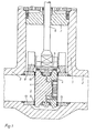
- the gate valve has a housing 1 with two pipe sockets 2, which delimit a through channel 3.
- the two pipe sockets 2 are separated from one another by a slide valve set.
- the slide assembly comprises two slide plates 4 arranged parallel to one another, one of which engages with a shoulder in a corresponding recess in the other slide plate 4.
- Each slide plate 4 is connected to a holding plate 5, which has a recess for receiving the base of a spindle 6.
- the spindle 6 is sealed by a cover 7 closing the housing 1.
- a drive not shown, via which the spindle 6 is adjusted in the axial direction. The spindle 6 moves the slide plates 4 in the open or in the closed position.
- Guide rings 8 are arranged above the through-channel 3 in the housing 1 on both sides of the slide assembly. When the gate valve is in the open position, the guide rings 8 ensure that the two slide plates 4 are properly guided, particularly when the valve is installed horizontally in a vertical pipeline.
- the slide plates 4 are guided within the housing 1 of the gate valve between the sealing surfaces 9 on the housing side, which are applied to the sealing rings 13 of the housing 1 by cladding.
- the housing-side sealing surfaces 9 are designed as circular surfaces, the smaller diameter of the circular ring corresponding to the diameter of the through-channel 3.
- the guide rings 8 also lie above the through-channel 3.
- the slide plates 4 are rectangular on their side facing away from the spindle 6, ie the lower half.
- the slide plates 4 are also provided with sealing surfaces 10 which cooperate with the sealing surfaces 9 on the housing side.
- these sealing surfaces 10 are circular. The diameters of this half circular surface correspond approximately to the diameters of the annular sealing surface 9 on the housing.
- the sealing surface 10 is enlarged beyond the surface size corresponding to the housing-side sealing surface.
- the sealing surface 10 is here limited on the one hand by the circumferential line of the smaller circle of the annular sealing surface in the upper half.
- the other boundary is formed by the circumferential line of half a square, the lower edge length of which corresponds to the diameter of the larger circle of the said circular surface.
- FIG. 3 The contact surfaces resulting from this enlargement of the sealing surfaces 10 of the slide plate 4 when the slide is open or closed are illustrated in FIG. 3.
- the previous embodiment of the sealing surfaces of the slide plate 4 is indicated as an annular surface by the dashed circle 12.
- the contact surface is enlarged by the portion of the surface 11 which extends beyond this circular line 12.
- the sliding plate 4 covers the entire width of the sealing surface 9 on the housing side in each slide position Guiding the slide plate 4 over its entire width.
- the invention is explained on a gate valve with two slide plates arranged in parallel. It can be applied in the same way to other plate shut-off systems with a single or several slide plates.
Landscapes
- Engineering & Computer Science (AREA)
- General Engineering & Computer Science (AREA)
- Mechanical Engineering (AREA)
- Sliding Valves (AREA)
- Packaging Of Annular Or Rod-Shaped Articles, Wearing Apparel, Cassettes, Or The Like (AREA)
Abstract
Description
- Die Erfindung betrifft einen Absperrschieber zum Verschließen von Rohrleitungen, in dessen Gehäuse eine oder mehrere Schieberplatten durch eine Spindel verstellbar angeordnet sind, wobei die Schieberplatten mit Dichtflächen versehen sind, die mit Dichtflächen im Gehäuse des Absperrschiebers zusammenwirken.
- Bei bekannten Absperrschiebern dieser Art sind die Dichtflächen auf den Schieberplatten und die gehäuseseitigen Dichtflächen etwa gleich groß. Muß ein solcher Absperrschieber, der zum Beispiel innerhalb einer Sicherheitsschaltung angeordnet ist, dann geschlossen werden, wenn zu beiden Seiten des Absperrschiebers unterschiedlich hohe Drücke anstehen, so treten Schwierigkeiten auf. Es besteht bei solchen hohen Druckunterschieden die Gefahr, daß sich die Schieberplatten innerhalb der gehäuseseitigen Führung schräg stellen. Diese Schrägstellung führt zu einer punktförmigen Auflage der Plattenkante des Absperrschiebers an der entsprechenden gehäuseseitigen Dichtfläche.
- Dadurch können diese Dichtflächen beschädigt werden, so daß die Dichtigkeit des Absperrschiebers beeinträchtigt werden kann. Weiterhin führt die Schrägstellung der Schieberplatten zu einer undefinierbaren Erhöhung der zum Schließen der Schieberplatten aufzuwendenden Stellkraft.
- Durch die vorliegende Erfindung sollen diese Nachteile vermieden werden. Der Erfindung liegt daher die Aufgabe zugrunde, einen Absperrschieber zu schaffen, bei dem eine sichere, gerade Führung der Schieberplatten auch bei einem erhöhten anstehenden Druckunterschied möglich ist.
- Diese Aufgabe wird erfindungsgemäß dadurch gelöst, daß die gegenüberliegenden Kanten einer Schieberplatte parallel zur Längsachse der Spindel verlaufen und ihr gegenseitiger Abstand der größten Breite der Dichtflächen im Gehäuse entspricht. Vorzugsweise ist vorgesehen, daß die Schieberplatten auf ihrer Spindel abgewandten Hälfte mit einer rechteckigen Außenkontur versehen sind und daß die Dichtflächen auf einer Hälfte der Schieberplatten durch eine kreisringförmige Fläche und auf der der Spindel abgewandten Hälfte durch eine Fläche gebildet sind, die zwischen der Umfangslinie des kleineren Kreises der Kreisringfläche und einem halben Quadrat mit einer dem Durchmesser des größeren Kreises entsprechenden Kantenlänge liegt.
- Durch die erfindungsgemäße Ausbildung der Schieberplatten ist die Dichtfläche um einen solchen Betrag vergrößert, daß während der gesamten Schieberbewegung eine sichere und gerade Führung der Schieberplatten über -die gesamte Breite ermöglicht wird. Eine Schrägstellung der Schieberplatten mit ihren nachteiligen Folgen ist dadurch vermieden. Zustätzlich wird die während der Schieberbewegung wirksame Auflagefläche der sich berührenden Dichtflächen vergrößert und damit die Flächenpressung herabgesetzt.
- Ein Ausführungsbeispiel der Erfindung ist in der Zeichnung dargestellt. Es zeigen:
- Fig. 1 einen Längsschnitt durch einen Absperrschieber gemäß der Erfindung,
- Fig. 2 den Schnitt II-II nach Fig. 1 und
- Fig. 3 das Zusammenwirken der Dichtflächen bei teilweise geschlossenem Schieber.
- Der Absperrschieber weist ein Gehäuse 1 mit zwei Rohrstutzen 2 auf, die einen Durchgangskanal 3 begrenzen. Die beiden Rohrstutzen 2 sind durch eine Schiebergarnitur voneinander getrennt. Die Schiebergarnitur umfaßt bei dem dargestellten Absperrschieber zwei parallel zueinander angeordnete Schieberplatten 4, von denen eine mit einem Absatz in eine entsprechende Ausnehmung in der anderen Schieberplatte 4 eingreift.
- Jede Schieberplatte 4 ist mit einer Halteplatte 5 verbunden, die eine Ausnehmung zur Aufnahme des Fußes einer Spindel 6 aufweist. Die Spindel 6 ist abgedichtet durch einen das Gehäuse 1 verschließenden Deckel 7 geführt. An das obere Ende der Spindel 6 greift ein nicht dargestellter Antrieb an, über den die Spindel 6 in axialer Richtung verstellt wird. Dabei fährt die Spindel 6 die Schieberplatten 4 in Offen- bzw. in Schließstellung.
- Oberhalb des Durchgangskanals 3 sind in dem Gehäuse 1 zu beiden Seiten der Schiebergarnitur Führungsringe 8 angeordnet. Die Führungsringe 8 sorgen bei Offenstellung des Absperrschiebers für eine ordnungsgemäße Führung der beiden Schieberplatten 4, insbesondere bei waagerechten Einbau der Armatur in eine senkrechte Rohrleitung.
- Die Schieberplatten 4 sind innerhalb des Gehäuses 1 des Absperrschiebers zwischen gehäuseseitigen Dichtflächen 9 geführt, die durch Auftragsschweißen auf Dichtringe 13 des Gehäuses 1 aufgebracht sind. Die gehäuseseitigen Dichtflächen 9 sind als kreisringförmige Flächen ausgebildet, wobei der kleinere Durchmesser des Kreisringes dem Durchmesser des Durchgangskanales 3 entspricht. In der gleichen Ebene wie die gehäuseseitigen Dichtflächen 9 liegen auch die Führungsringe 8 oberhalb des Durchgangskanales 3.
- Abweichend von der bisherigen Ausführungsform sind die Schieberplatten 4 auf ihrer der Spindel 6 abgewandten, also der unteren, Hälfte rechteckig ausgebildet. Die Schieberplatten 4 sind ebenfalls mit Dichtflächen 10 versehen, die mit den gehäuseseitigen Dichtflächen 9 zusammenwirken. Auf der oberen, der Spindel 6 zugewandten Hälfte der Schieberplatten 4 sind diese Dichtflächen 10 kreisringförmig ausgebildet. Die Durchmesser dieser halben Kreisringfläche stimmen etwa mit den Durchmessern der kreisringförmigen, gehäuseseitigen Dichtfläche 9 überein.
- Auf der unteren, rechteckig ausgebildeten Hälfte der Schieberplatten 4 ist die Dichtfläche 10 über die der gehäuseseitigen Dichtfläche entsprechende Flächengröße hinaus vergrößert. Die Dichtfläche 10 ist hier einerseits begrenzt von der Umfangslinie des kleineren Kreises der kreisringförmigen Dichtfläche in der oberen Hälfte. Die andere Umgrenzung ist gebildet durch die Umfangslinie eines halben Quadrates, dessen untere Kantenlänge dem Durchmesser des größeren Kreises der genannten Kreisringfläche entspricht.
- Die sich aus dieser Vergrößerung der Dichtflächen 10 der Schieberplatte 4 bei Offen- bzw. Schließstellung des Schiebers ergebenden Auflageflächen sind in der Fig. 3 verdeutlicht. In dieser Figur ist angenommen, daß sich der Schieber in einer teilweise geschlossenen Stellung befindet. Der Anteil der Dichtflächen 10 der Schieberplatte 4, der in dieser Stellung des Schiebers an der gehäuseseitigen Dichtfläche 9 anliegt, ist durch die doppelt schraffierte Fläche 11 wiedergegeben. In der Fig. 3 ist durch die gestrichelt gezeichnete Kreislinie 12 die bisherige Ausführungsform der Dichtflächen der Schieberplatte 4 als Kreisringfläche angedeutet. Um den über diese Kreislinie 12 hinausgehenden Anteil der Fläche 11 ist bei der erfindungsgemäßen Ausbildung der Schieberplatte 4 die Auflagefläche vergrößert. Da darüber hinaus die Breite der Dichtfläche 10 der erfindungsgemäßen Schieberplatte 4 gleich dem größeren Durchmesser der gehäuseseitigen Dichtfläche 9 entspricht, überdeckt die Schieberplatte 4 in jeder Schieberstellung die gesamte Breite der gehäuseseitigen Dichtfläche 9. Daraus ergibt sich im Gegensatz zu der bisherigen Ausbildung der Dichtflächen 10 eine Führung der Schieberplatte 4 über deren gesamte Breite.
- Die Erfindung ist an einem Absperrschieber mit zwei parallel angeordnete Schieberplatten erläutert. Sie läßt sich in gleicher Weise auf andere Plattenabsperrsysteme mit einer einzigen oder mehreren Schieberplatten anwenden.
Claims (2)
Applications Claiming Priority (2)
| Application Number | Priority Date | Filing Date | Title |
|---|---|---|---|
| DE19803003646 DE3003646A1 (de) | 1980-02-01 | 1980-02-01 | Absperrschieber |
| DE3003646 | 1980-02-01 |
Publications (2)
| Publication Number | Publication Date |
|---|---|
| EP0033357A1 true EP0033357A1 (de) | 1981-08-12 |
| EP0033357B1 EP0033357B1 (de) | 1985-04-24 |
Family
ID=6093482
Family Applications (1)
| Application Number | Title | Priority Date | Filing Date |
|---|---|---|---|
| EP80105280A Expired EP0033357B1 (de) | 1980-02-01 | 1980-09-04 | Absperrschieber |
Country Status (4)
| Country | Link |
|---|---|
| EP (1) | EP0033357B1 (de) |
| CS (1) | CS256306B1 (de) |
| DD (1) | DD153908A1 (de) |
| DE (1) | DE3003646A1 (de) |
Cited By (1)
| Publication number | Priority date | Publication date | Assignee | Title |
|---|---|---|---|---|
| CN105065700A (zh) * | 2015-07-13 | 2015-11-18 | 哈托利海托阀门(杭州)有限公司 | 一种自密封式闸阀结构 |
Citations (1)
| Publication number | Priority date | Publication date | Assignee | Title |
|---|---|---|---|---|
| DE1868900U (de) * | 1962-01-29 | 1963-03-14 | Siemens Schukkertwerke Ag | Flachschieber. |
Family Cites Families (8)
| Publication number | Priority date | Publication date | Assignee | Title |
|---|---|---|---|---|
| CH225217A (de) * | 1942-01-24 | 1943-01-15 | Oederlin Cie Ag | Absperrschieber. |
| US3193249A (en) * | 1962-01-26 | 1965-07-06 | A P Smith Mfg Company | Valve structure |
| GB1022884A (en) * | 1964-02-15 | 1966-03-16 | George Meagher | Improvements in or relating to fluid-controlling gate valves |
| US3349789A (en) * | 1965-05-24 | 1967-10-31 | Gray Tool Co | Lubricated wedge gate valve |
| US3559949A (en) * | 1967-02-16 | 1971-02-02 | Ernest Muller | Gate valve |
| FR2232710B1 (de) * | 1973-06-05 | 1976-09-17 | Z Im Leite | |
| US3893652A (en) * | 1973-10-05 | 1975-07-08 | Acf Ind Inc | Means connecting gate valve and valve stem |
| US4179099A (en) * | 1978-07-03 | 1979-12-18 | Petroleum Designers, Inc. | Expanding gate valve |
-
1980
- 1980-02-01 DE DE19803003646 patent/DE3003646A1/de active Granted
- 1980-09-04 EP EP80105280A patent/EP0033357B1/de not_active Expired
- 1980-10-29 DD DD22481180A patent/DD153908A1/de not_active IP Right Cessation
-
1981
- 1981-01-26 CS CS55981A patent/CS256306B1/cs unknown
Patent Citations (1)
| Publication number | Priority date | Publication date | Assignee | Title |
|---|---|---|---|---|
| DE1868900U (de) * | 1962-01-29 | 1963-03-14 | Siemens Schukkertwerke Ag | Flachschieber. |
Cited By (2)
| Publication number | Priority date | Publication date | Assignee | Title |
|---|---|---|---|---|
| CN105065700A (zh) * | 2015-07-13 | 2015-11-18 | 哈托利海托阀门(杭州)有限公司 | 一种自密封式闸阀结构 |
| CN105065700B (zh) * | 2015-07-13 | 2017-07-18 | 哈托利海托阀门(杭州)有限公司 | 一种自密封式闸阀结构 |
Also Published As
| Publication number | Publication date |
|---|---|
| CS8100559A2 (en) | 1987-06-11 |
| DD153908A1 (de) | 1982-02-10 |
| DE3003646A1 (de) | 1981-08-06 |
| CS254306B2 (en) | 1988-01-15 |
| EP0033357B1 (de) | 1985-04-24 |
| DE3003646C2 (de) | 1988-11-10 |
| CS256306B1 (en) | 1988-04-15 |
Similar Documents
| Publication | Publication Date | Title |
|---|---|---|
| DE3043871C2 (de) | ||
| DE2950182A1 (de) | Dichtungsanordnung | |
| DE69004873T2 (de) | Keramische Scheibe für Ventile und Ventile, ausgerüstet mit solchen Scheiben. | |
| DE3320809C2 (de) | ||
| DE69224895T2 (de) | Vakuumschieber | |
| DE1170735B (de) | Absperrschieber | |
| EP0195178B1 (de) | Durchgangs- und Absperrventil | |
| CH629882A5 (de) | Ventil zur steuerung fluidischer medien. | |
| EP0174486A2 (de) | Vorrichtung zum Absperren einer Rohrleitung | |
| EP0033357B1 (de) | Absperrschieber | |
| DE3542062A1 (de) | Tellerventil | |
| DE1450671B2 (de) | Rueckschlagventil mit einem ringfoermigen elastischen ventil verschlusstueck | |
| DE2606042A1 (de) | Ventil zum absperren, drosseln oder regeln | |
| DE2845072A1 (de) | Einschraubzapfen | |
| DE2749352C3 (de) | Druckmittelsteuereinrichtung, insbesondere für hydrostatische Lenkeinrichtungen von Kraftfahrzeugen | |
| DE2933545C2 (de) | ||
| DE2414632C2 (de) | Betätigungsvorrichtung für ein Wegeventil zur Druckmittelsteuerung | |
| EP0231754A1 (de) | Hubmagnet | |
| EP0102443A1 (de) | Mehrwege-Schieberventil | |
| DE3608577C2 (de) | ||
| EP0088881B1 (de) | Pneumatisches Doppelsitzventil | |
| DE1957560A1 (de) | Flachschieber | |
| EP0329800A1 (de) | Ventiloberteil | |
| DE3337652C2 (de) | ||
| DE3434696A1 (de) | Blendenregulierventil |
Legal Events
| Date | Code | Title | Description |
|---|---|---|---|
| PUAI | Public reference made under article 153(3) epc to a published international application that has entered the european phase |
Free format text: ORIGINAL CODE: 0009012 |
|
| AK | Designated contracting states |
Designated state(s): BE FR GB IT |
|
| 17P | Request for examination filed |
Effective date: 19810919 |
|
| ITF | It: translation for a ep patent filed | ||
| GRAA | (expected) grant |
Free format text: ORIGINAL CODE: 0009210 |
|
| AK | Designated contracting states |
Designated state(s): BE FR GB IT |
|
| ET | Fr: translation filed | ||
| PLBE | No opposition filed within time limit |
Free format text: ORIGINAL CODE: 0009261 |
|
| STAA | Information on the status of an ep patent application or granted ep patent |
Free format text: STATUS: NO OPPOSITION FILED WITHIN TIME LIMIT |
|
| 26N | No opposition filed | ||
| PGFP | Annual fee paid to national office [announced via postgrant information from national office to epo] |
Ref country code: BE Payment date: 19910731 Year of fee payment: 12 |
|
| PGFP | Annual fee paid to national office [announced via postgrant information from national office to epo] |
Ref country code: GB Payment date: 19920608 Year of fee payment: 13 |
|
| PGFP | Annual fee paid to national office [announced via postgrant information from national office to epo] |
Ref country code: FR Payment date: 19920805 Year of fee payment: 13 |
|
| PG25 | Lapsed in a contracting state [announced via postgrant information from national office to epo] |
Ref country code: BE Effective date: 19920930 |
|
| BERE | Be: lapsed |
Owner name: DEUTSCHE BABCOCK A.G. Effective date: 19920930 |
|
| PG25 | Lapsed in a contracting state [announced via postgrant information from national office to epo] |
Ref country code: GB Effective date: 19930904 |
|
| GBPC | Gb: european patent ceased through non-payment of renewal fee |
Effective date: 19930904 |
|
| PG25 | Lapsed in a contracting state [announced via postgrant information from national office to epo] |
Ref country code: FR Free format text: LAPSE BECAUSE OF NON-PAYMENT OF DUE FEES Effective date: 19940531 |
|
| REG | Reference to a national code |
Ref country code: FR Ref legal event code: ST |