EP0033379A1 - Valve relais pour installations de freinage à double circuit fonctionnant avec un fluide sous pression et qui sont réglées en fonction de la charge - Google Patents
Valve relais pour installations de freinage à double circuit fonctionnant avec un fluide sous pression et qui sont réglées en fonction de la charge Download PDFInfo
- Publication number
- EP0033379A1 EP0033379A1 EP80107796A EP80107796A EP0033379A1 EP 0033379 A1 EP0033379 A1 EP 0033379A1 EP 80107796 A EP80107796 A EP 80107796A EP 80107796 A EP80107796 A EP 80107796A EP 0033379 A1 EP0033379 A1 EP 0033379A1
- Authority
- EP
- European Patent Office
- Prior art keywords
- brake
- circuit
- control
- pressure
- chamber
- Prior art date
- Legal status (The legal status is an assumption and is not a legal conclusion. Google has not performed a legal analysis and makes no representation as to the accuracy of the status listed.)
- Granted
Links
- 230000001419 dependent effect Effects 0.000 title description 9
- 239000012530 fluid Substances 0.000 title 1
- 230000001105 regulatory effect Effects 0.000 claims abstract description 9
- 230000001276 controlling effect Effects 0.000 claims abstract 3
- 230000002950 deficient Effects 0.000 claims abstract 2
- 238000009423 ventilation Methods 0.000 claims description 4
- 238000009434 installation Methods 0.000 abstract description 2
- 230000004913 activation Effects 0.000 description 2
- 230000000694 effects Effects 0.000 description 2
- 239000002655 kraft paper Substances 0.000 description 1
- 230000001960 triggered effect Effects 0.000 description 1
- 238000013022 venting Methods 0.000 description 1
Images
Classifications
-
- B—PERFORMING OPERATIONS; TRANSPORTING
- B60—VEHICLES IN GENERAL
- B60T—VEHICLE BRAKE CONTROL SYSTEMS OR PARTS THEREOF; BRAKE CONTROL SYSTEMS OR PARTS THEREOF, IN GENERAL; ARRANGEMENT OF BRAKING ELEMENTS ON VEHICLES IN GENERAL; PORTABLE DEVICES FOR PREVENTING UNWANTED MOVEMENT OF VEHICLES; VEHICLE MODIFICATIONS TO FACILITATE COOLING OF BRAKES
- B60T15/00—Construction arrangement, or operation of valves incorporated in power brake systems and not covered by groups B60T11/00 or B60T13/00
- B60T15/02—Application and release valves
- B60T15/18—Triple or other relay valves which allow step-wise application or release and which are actuated by brake-pipe pressure variation to connect brake cylinders or equivalent to compressed air or vacuum source or atmosphere
- B60T15/20—Triple or other relay valves which allow step-wise application or release and which are actuated by brake-pipe pressure variation to connect brake cylinders or equivalent to compressed air or vacuum source or atmosphere controlled by two fluid pressures
-
- B—PERFORMING OPERATIONS; TRANSPORTING
- B60—VEHICLES IN GENERAL
- B60T—VEHICLE BRAKE CONTROL SYSTEMS OR PARTS THEREOF; BRAKE CONTROL SYSTEMS OR PARTS THEREOF, IN GENERAL; ARRANGEMENT OF BRAKING ELEMENTS ON VEHICLES IN GENERAL; PORTABLE DEVICES FOR PREVENTING UNWANTED MOVEMENT OF VEHICLES; VEHICLE MODIFICATIONS TO FACILITATE COOLING OF BRAKES
- B60T13/00—Transmitting braking action from initiating means to ultimate brake actuator with power assistance or drive; Brake systems incorporating such transmitting means, e.g. air-pressure brake systems
- B60T13/10—Transmitting braking action from initiating means to ultimate brake actuator with power assistance or drive; Brake systems incorporating such transmitting means, e.g. air-pressure brake systems with fluid assistance, drive, or release
- B60T13/58—Combined or convertible systems
- B60T13/581—Combined or convertible systems both hydraulic and pneumatic
- B60T13/583—Combined or convertible systems both hydraulic and pneumatic using converters
-
- B—PERFORMING OPERATIONS; TRANSPORTING
- B60—VEHICLES IN GENERAL
- B60T—VEHICLE BRAKE CONTROL SYSTEMS OR PARTS THEREOF; BRAKE CONTROL SYSTEMS OR PARTS THEREOF, IN GENERAL; ARRANGEMENT OF BRAKING ELEMENTS ON VEHICLES IN GENERAL; PORTABLE DEVICES FOR PREVENTING UNWANTED MOVEMENT OF VEHICLES; VEHICLE MODIFICATIONS TO FACILITATE COOLING OF BRAKES
- B60T8/00—Arrangements for adjusting wheel-braking force to meet varying vehicular or ground-surface conditions, e.g. limiting or varying distribution of braking force
- B60T8/18—Arrangements for adjusting wheel-braking force to meet varying vehicular or ground-surface conditions, e.g. limiting or varying distribution of braking force responsive to vehicle weight or load, e.g. load distribution
-
- B—PERFORMING OPERATIONS; TRANSPORTING
- B60—VEHICLES IN GENERAL
- B60T—VEHICLE BRAKE CONTROL SYSTEMS OR PARTS THEREOF; BRAKE CONTROL SYSTEMS OR PARTS THEREOF, IN GENERAL; ARRANGEMENT OF BRAKING ELEMENTS ON VEHICLES IN GENERAL; PORTABLE DEVICES FOR PREVENTING UNWANTED MOVEMENT OF VEHICLES; VEHICLE MODIFICATIONS TO FACILITATE COOLING OF BRAKES
- B60T8/00—Arrangements for adjusting wheel-braking force to meet varying vehicular or ground-surface conditions, e.g. limiting or varying distribution of braking force
- B60T8/18—Arrangements for adjusting wheel-braking force to meet varying vehicular or ground-surface conditions, e.g. limiting or varying distribution of braking force responsive to vehicle weight or load, e.g. load distribution
- B60T8/1881—Arrangements for adjusting wheel-braking force to meet varying vehicular or ground-surface conditions, e.g. limiting or varying distribution of braking force responsive to vehicle weight or load, e.g. load distribution characterised by failure-responsive means
Definitions
- the invention relates to a relay valve according to the preamble of claim 1.
- DE-OS 2 907 426 describes hydraulically controlled dual-circuit air brake systems whose brake pressure in the rear axle brake circuit is regulated in a load-dependent manner, with a hydraulically controlled pneumatic brake force regulator in a first embodiment and the load-dependent brake pressure in a second embodiment with a purely pneumatic brake force regulator.
- a relay valve is in DE-OS 2 907 426 Proposed, which is controlled by the hydraulic brake pressure sensor of the hydraulic control part of the brake system and the load-dependent controlled brake pressure of the rear axle brake circuit and whose controlled brake pressure in the front axle brake circuit is subject in a certain ratio to the load-dependent pressure conditions of the rear axle brake circuit.
- the present invention is therefore based on the object of creating a relay valve of the type mentioned which, in the event of failure of the load-dependent controlled rear axle brake circuit, controls a sufficient brake pressure in the front axle brake circuit.
- the brake pressure becomes the rule Piston acted upon reaction area reduced by the size of the third control surface, whereby the control pressure to be applied by the foot forces is reduced in the same ratio, so that despite failure of the rear axle brake circuit, the brake pressure in the front axle brake circuit achieves a sufficient braking effect.
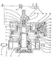
- a control piston 2 is arranged, the lower surface 3 of which forms an outlet valve 3, 4 with the upper surface 4 of a double valve body 5 guided in the lower part of the housing 1, the venting of which into the atmosphere takes place via a bore 6 of the double valve body 5 and a ventilation opening 7 takes place.
- the double valve body 5 forms, with an annular surface 8 and a housing-fixed stop 9 designed as a valve seat, an inlet valve 8, 9 which, via a housing chamber 14, establishes a connection between an inlet connection 11 connected to a compressed air source 10 and an outlet connection 13 connected to the brake cylinders 12.
- the double valve body 5 is supported on a spring 15 so that the outlet valve 3, 4 is biased by the spring 15 in the closed position.
- the control piston 2 has a first upper control surface 16, which is part of a first control chamber 17 located above this piston 2, which produces a connection to a hydraulic brake pressure transmitter 19 via a connection 18.
- a second control surface 20 of the relay piston 2 forms part of a second control chamber 21, which is connected via a connection 22 to the brake pressure of the rear axle brake circuit 24 which is regulated in a load-dependent manner by means of a brake force regulator 23.
- a third control surface 25, which is part of a third control chamber 26, can be connected via housing bores 27 and 28 to the housing chamber 14 located below the control piston 2.
- a piston-shaped valve body 29 is arranged in the housing 1 of the relay valve such that one end of the valve body 29 with a valve seat of a housing wall 30 forms a valve 29, 30, which connects the third control chamber 26 and the housing chamber 14 or between the Bores 27 and 28 interrupts or opens depending on its position.
- a chamber 31 arranged above the valve body 29 is connected to the second control chamber 21 via a housing bore 32, the pressure in the chamber 31, which acts on the surface 33 at the other end of the valve body 29, triggers a closed position of the valve.
- An annular surface 34 of the valve body 29, which forms part of an annular chamber 35, lies opposite the surface 33 and can be acted upon via the bore 28 by the pressure of the chamber 14 in the opening direction of the valve 29, 30.
- valve 29, 30 is closed during the braking operation, since the ratio of the surfaces 33 and 34 is designed such that the force acting on the surface 33 predominates.
Landscapes
- Engineering & Computer Science (AREA)
- Transportation (AREA)
- Mechanical Engineering (AREA)
- Physics & Mathematics (AREA)
- Fluid Mechanics (AREA)
- Valves And Accessory Devices For Braking Systems (AREA)
- Braking Systems And Boosters (AREA)
- Hydraulic Control Valves For Brake Systems (AREA)
Priority Applications (1)
| Application Number | Priority Date | Filing Date | Title |
|---|---|---|---|
| AT80107796T ATE2886T1 (de) | 1980-02-01 | 1980-12-11 | Relaisventil in lastabhaengig geregelten zweikreis-druckmittelbremsanlagen. |
Applications Claiming Priority (2)
| Application Number | Priority Date | Filing Date | Title |
|---|---|---|---|
| DE3003627 | 1980-02-01 | ||
| DE19803003627 DE3003627A1 (de) | 1980-02-01 | 1980-02-01 | Relaisventil in lastabhaengig geregelten zweikreis-druckmittelbremsanlagen |
Publications (2)
| Publication Number | Publication Date |
|---|---|
| EP0033379A1 true EP0033379A1 (fr) | 1981-08-12 |
| EP0033379B1 EP0033379B1 (fr) | 1983-03-30 |
Family
ID=6093470
Family Applications (1)
| Application Number | Title | Priority Date | Filing Date |
|---|---|---|---|
| EP80107796A Expired EP0033379B1 (fr) | 1980-02-01 | 1980-12-11 | Valve relais pour installations de freinage à double circuit fonctionnant avec un fluide sous pression et qui sont réglées en fonction de la charge |
Country Status (3)
| Country | Link |
|---|---|
| EP (1) | EP0033379B1 (fr) |
| AT (1) | ATE2886T1 (fr) |
| DE (2) | DE3003627A1 (fr) |
Cited By (11)
| Publication number | Priority date | Publication date | Assignee | Title |
|---|---|---|---|---|
| EP0088911A1 (fr) * | 1982-03-17 | 1983-09-21 | Robert Bosch Gmbh | Système de freinage à deux circuits avec fluide sous pression |
| RU2222444C2 (ru) * | 2002-04-05 | 2004-01-27 | ОАО "Транспневматика" | Авторегулятор давления воздуха в тормозном цилиндре |
| RU2232689C2 (ru) * | 2002-01-28 | 2004-07-20 | Гуляев Виктор Васильевич | Автоматический пневматический стояночный тормоз железнодорожного транспортного средства с регулируемой величиной тормозного нажатия |
| RU2232692C1 (ru) * | 2003-03-26 | 2004-07-20 | ООО "Желдорконсалтинг" | Система для управления тормозами поезда с локомотивной тягой |
| RU2235653C2 (ru) * | 2002-07-02 | 2004-09-10 | Маликов Николай Васильевич | Способ действия автоматического стояночного тормоза |
| RU2238204C1 (ru) * | 2003-01-04 | 2004-10-20 | Государственное унитарное предприятие "Уральское отделение Всероссийского научно-исследовательского института железнодорожного транспорта" | Устройство блокировки тормозов локомотива |
| RU2247045C2 (ru) * | 2002-10-11 | 2005-02-27 | Маликов Николай Васильевич | Способ блокировки тормозов железнодорожного тягового средства |
| RU2286897C1 (ru) * | 2005-04-04 | 2006-11-10 | Виктор Васильевич Гуляев | Автоматический механический стояночный тормоз железнодорожного подвижного состава с регулируемым тормозным нажатием и дистанционным ручным управлением |
| RU2299142C1 (ru) * | 2005-11-17 | 2007-05-20 | Денис Николаевич Маликов | Способ блокировки приборов управления тормозами железнодорожного тягового средства |
| RU2302954C1 (ru) * | 2006-04-06 | 2007-07-20 | Николай Васильевич Маликов | Способ прекращения действия автоматического стояночного тормоза железнодорожного подвижного состава и устройство для его реализации |
| RU186503U1 (ru) * | 2017-12-29 | 2019-01-22 | Федеральное государственное бюджетное образовательное учреждение высшего образования Иркутский государственный университет путей сообщения (ФГБОУ ВО ИрГУПС) | Устройство автоматической ликвидации сверхзарядного давления крана машиниста усл. N 394(395) |
Citations (1)
| Publication number | Priority date | Publication date | Assignee | Title |
|---|---|---|---|---|
| DE2907426A1 (de) * | 1979-02-26 | 1981-02-12 | Wabco Fahrzeugbremsen Gmbh | Zweikreis-druckmittelbremsanlage mit lastabhaengiger regelung fuer kraftfahrzeuge |
Family Cites Families (4)
| Publication number | Priority date | Publication date | Assignee | Title |
|---|---|---|---|---|
| DE1755953B1 (de) * | 1968-07-15 | 1971-11-04 | Graubremse Gmbh | Mehrkreisbremsventil fuer Fahrzeugbremsanlagen |
| DE2548992C3 (de) * | 1975-11-03 | 1978-07-27 | Graubremse Gmbh, 6900 Heidelberg | Zweileitungs-Druckluftbremsanlage für Kraftfahrzeuge mit Anhänger, mit einem Anhängersteuerventil und einem Sperrventil |
| NL181639C (nl) * | 1976-01-02 | 1987-10-01 | Bendix Westinghouse Ltd | Met een fluidum onder druk werkend voertuigremstelsel voor een motorvoertuig en een daardoor getrokken voertuig. |
| DE2820107B2 (de) * | 1978-05-09 | 1980-03-06 | Graubremse Gmbh, 6900 Heidelberg | Druckluft-Bremsanlage für Kraftfahrzeuge |
-
1980
- 1980-02-01 DE DE19803003627 patent/DE3003627A1/de not_active Withdrawn
- 1980-12-11 AT AT80107796T patent/ATE2886T1/de not_active IP Right Cessation
- 1980-12-11 DE DE8080107796T patent/DE3062554D1/de not_active Expired
- 1980-12-11 EP EP80107796A patent/EP0033379B1/fr not_active Expired
Patent Citations (1)
| Publication number | Priority date | Publication date | Assignee | Title |
|---|---|---|---|---|
| DE2907426A1 (de) * | 1979-02-26 | 1981-02-12 | Wabco Fahrzeugbremsen Gmbh | Zweikreis-druckmittelbremsanlage mit lastabhaengiger regelung fuer kraftfahrzeuge |
Cited By (11)
| Publication number | Priority date | Publication date | Assignee | Title |
|---|---|---|---|---|
| EP0088911A1 (fr) * | 1982-03-17 | 1983-09-21 | Robert Bosch Gmbh | Système de freinage à deux circuits avec fluide sous pression |
| RU2232689C2 (ru) * | 2002-01-28 | 2004-07-20 | Гуляев Виктор Васильевич | Автоматический пневматический стояночный тормоз железнодорожного транспортного средства с регулируемой величиной тормозного нажатия |
| RU2222444C2 (ru) * | 2002-04-05 | 2004-01-27 | ОАО "Транспневматика" | Авторегулятор давления воздуха в тормозном цилиндре |
| RU2235653C2 (ru) * | 2002-07-02 | 2004-09-10 | Маликов Николай Васильевич | Способ действия автоматического стояночного тормоза |
| RU2247045C2 (ru) * | 2002-10-11 | 2005-02-27 | Маликов Николай Васильевич | Способ блокировки тормозов железнодорожного тягового средства |
| RU2238204C1 (ru) * | 2003-01-04 | 2004-10-20 | Государственное унитарное предприятие "Уральское отделение Всероссийского научно-исследовательского института железнодорожного транспорта" | Устройство блокировки тормозов локомотива |
| RU2232692C1 (ru) * | 2003-03-26 | 2004-07-20 | ООО "Желдорконсалтинг" | Система для управления тормозами поезда с локомотивной тягой |
| RU2286897C1 (ru) * | 2005-04-04 | 2006-11-10 | Виктор Васильевич Гуляев | Автоматический механический стояночный тормоз железнодорожного подвижного состава с регулируемым тормозным нажатием и дистанционным ручным управлением |
| RU2299142C1 (ru) * | 2005-11-17 | 2007-05-20 | Денис Николаевич Маликов | Способ блокировки приборов управления тормозами железнодорожного тягового средства |
| RU2302954C1 (ru) * | 2006-04-06 | 2007-07-20 | Николай Васильевич Маликов | Способ прекращения действия автоматического стояночного тормоза железнодорожного подвижного состава и устройство для его реализации |
| RU186503U1 (ru) * | 2017-12-29 | 2019-01-22 | Федеральное государственное бюджетное образовательное учреждение высшего образования Иркутский государственный университет путей сообщения (ФГБОУ ВО ИрГУПС) | Устройство автоматической ликвидации сверхзарядного давления крана машиниста усл. N 394(395) |
Also Published As
| Publication number | Publication date |
|---|---|
| EP0033379B1 (fr) | 1983-03-30 |
| DE3003627A1 (de) | 1981-08-06 |
| DE3062554D1 (en) | 1983-05-05 |
| ATE2886T1 (de) | 1983-04-15 |
Similar Documents
| Publication | Publication Date | Title |
|---|---|---|
| EP0033379B1 (fr) | Valve relais pour installations de freinage à double circuit fonctionnant avec un fluide sous pression et qui sont réglées en fonction de la charge | |
| DE2520144C3 (de) | Relaisventil zur Begrenzung und Steuerung des Luftdrucks in einer Federspeicher-Bremsbetätigungseinrichtung | |
| DE2008025A1 (de) | Hydraulische Bremseinrichtung für Fahrzeuge | |
| DE2706786A1 (de) | Mit unter druck stehendem stroemungsmittel arbeitendes bremssystem fuer ein fahrzeug | |
| EP0046166B1 (fr) | Installation de frein à deux conduites réglée en fonction de la charge, pour une remorque | |
| EP0043894B1 (fr) | Installation pour la correction du freinage commandée en fonction de la charge | |
| DE2907426C2 (fr) | ||
| DE2739884B2 (de) | Lastabhängige Bremskraft-Regeleinrichtung für druckluftbetatigbare Kraftfahrzeug- und Anhängefahrzeug-Bremsanlagen | |
| DE2421915B2 (de) | Relaisventil für eine blockiergeschützte Fahrzeug-Druckluftbremsanlage | |
| DE2646288B2 (de) | Lastabhängige Bremskraft-Regeleinrichtung | |
| EP0090908B2 (fr) | Valve-pilote pour freins à pression | |
| DE69328877T2 (de) | Blockiergeschützte Bremseinrichtung für Kraftfahrzeuge | |
| DE2820142A1 (de) | Mehrkreisbremsventil fuer druckluftbremsanlagen von kraftfahrzeugen | |
| EP0312718B1 (fr) | Valve de commande de pression de freinage commandée par deux circuits | |
| EP0169303B1 (fr) | Valve de commande pour remorques | |
| DE2609018A1 (de) | Stroemungsmittelbetaetigte bremsanlage | |
| DE2939907A1 (de) | Zweikreis-bremsanlage | |
| DE2849762C2 (de) | Fluiddruckbetätigtes Zweikreisbremssystem für Kraftfahrzeuge | |
| DE2401337C3 (de) | Drucksteueranordnung für eine Fahrzeugbremsanlage | |
| EP0026346B1 (fr) | Valve de freinage à commande mécanique, en particulier valve de freinage actionnée au pied pour systèmes de freinage à double circuit dans des véhicules | |
| DE2814431C2 (de) | Bremskraftregler | |
| EP0163015B1 (fr) | Valve de commande de remorque | |
| EP0124726A1 (fr) | Valve de commande pour remorques | |
| DE2417613C3 (de) | Relaisventil zur Begrenzung und Steuerung des Luftdrucks in einer Federspeicher-Bremsbetätigungseinrichtung | |
| DE1814723A1 (de) | Bremsanlage fuer Fahrzeuge,insbesondere fuer Kraftfahrzeuge |
Legal Events
| Date | Code | Title | Description |
|---|---|---|---|
| PUAI | Public reference made under article 153(3) epc to a published international application that has entered the european phase |
Free format text: ORIGINAL CODE: 0009012 |
|
| AK | Designated contracting states |
Designated state(s): AT CH DE FR GB IT NL SE |
|
| 17P | Request for examination filed |
Effective date: 19810619 |
|
| RAP1 | Party data changed (applicant data changed or rights of an application transferred) |
Owner name: WABCO WESTINGHOUSE FAHRZEUGBREMSEN GMBH |
|
| ITF | It: translation for a ep patent filed | ||
| GRAA | (expected) grant |
Free format text: ORIGINAL CODE: 0009210 |
|
| AK | Designated contracting states |
Designated state(s): AT CH DE FR GB IT LI NL SE |
|
| REF | Corresponds to: |
Ref document number: 2886 Country of ref document: AT Date of ref document: 19830415 Kind code of ref document: T |
|
| REF | Corresponds to: |
Ref document number: 3062554 Country of ref document: DE Date of ref document: 19830505 |
|
| ET | Fr: translation filed | ||
| PGFP | Annual fee paid to national office [announced via postgrant information from national office to epo] |
Ref country code: CH Payment date: 19840109 Year of fee payment: 4 |
|
| PGFP | Annual fee paid to national office [announced via postgrant information from national office to epo] |
Ref country code: AT Payment date: 19841130 Year of fee payment: 5 |
|
| PGFP | Annual fee paid to national office [announced via postgrant information from national office to epo] |
Ref country code: NL Payment date: 19841231 Year of fee payment: 5 |
|
| PG25 | Lapsed in a contracting state [announced via postgrant information from national office to epo] |
Ref country code: AT Effective date: 19851211 |
|
| PG25 | Lapsed in a contracting state [announced via postgrant information from national office to epo] |
Ref country code: LI Effective date: 19851231 Ref country code: CH Effective date: 19851231 |
|
| PG25 | Lapsed in a contracting state [announced via postgrant information from national office to epo] |
Ref country code: NL Effective date: 19860701 |
|
| NLV4 | Nl: lapsed or anulled due to non-payment of the annual fee | ||
| REG | Reference to a national code |
Ref country code: CH Ref legal event code: PL |
|
| PGFP | Annual fee paid to national office [announced via postgrant information from national office to epo] |
Ref country code: SE Payment date: 19901213 Year of fee payment: 11 |
|
| ITTA | It: last paid annual fee | ||
| PG25 | Lapsed in a contracting state [announced via postgrant information from national office to epo] |
Ref country code: SE Effective date: 19911212 |
|
| PGFP | Annual fee paid to national office [announced via postgrant information from national office to epo] |
Ref country code: GB Payment date: 19921201 Year of fee payment: 13 |
|
| PGFP | Annual fee paid to national office [announced via postgrant information from national office to epo] |
Ref country code: FR Payment date: 19921221 Year of fee payment: 13 |
|
| PG25 | Lapsed in a contracting state [announced via postgrant information from national office to epo] |
Ref country code: GB Effective date: 19931211 |
|
| GBPC | Gb: european patent ceased through non-payment of renewal fee |
Effective date: 19931211 |
|
| PG25 | Lapsed in a contracting state [announced via postgrant information from national office to epo] |
Ref country code: FR Effective date: 19940831 |
|
| REG | Reference to a national code |
Ref country code: FR Ref legal event code: ST |
|
| EUG | Se: european patent has lapsed |
Ref document number: 80107796.7 Effective date: 19920704 |
|
| PGFP | Annual fee paid to national office [announced via postgrant information from national office to epo] |
Ref country code: DE Payment date: 19951220 Year of fee payment: 16 |
|
| PG25 | Lapsed in a contracting state [announced via postgrant information from national office to epo] |
Ref country code: DE Effective date: 19970902 |
|
| PLBE | No opposition filed within time limit |
Free format text: ORIGINAL CODE: 0009261 |
|
| STAA | Information on the status of an ep patent application or granted ep patent |
Free format text: STATUS: NO OPPOSITION FILED WITHIN TIME LIMIT |