EP0033491B1 - Châssis pour structures, en particulier pour vitrines et meubles d'exposition - Google Patents
Châssis pour structures, en particulier pour vitrines et meubles d'exposition Download PDFInfo
- Publication number
- EP0033491B1 EP0033491B1 EP81100476A EP81100476A EP0033491B1 EP 0033491 B1 EP0033491 B1 EP 0033491B1 EP 81100476 A EP81100476 A EP 81100476A EP 81100476 A EP81100476 A EP 81100476A EP 0033491 B1 EP0033491 B1 EP 0033491B1
- Authority
- EP
- European Patent Office
- Prior art keywords
- screw
- frame according
- frame
- profiled section
- screws
- Prior art date
- Legal status (The legal status is an assumption and is not a legal conclusion. Google has not performed a legal analysis and makes no representation as to the accuracy of the status listed.)
- Expired
Links
- XAGFODPZIPBFFR-UHFFFAOYSA-N aluminium Chemical compound [Al] XAGFODPZIPBFFR-UHFFFAOYSA-N 0.000 claims description 3
- 229910052782 aluminium Inorganic materials 0.000 claims description 3
- 239000004411 aluminium Substances 0.000 claims 1
- 230000003014 reinforcing effect Effects 0.000 claims 1
- 238000010276 construction Methods 0.000 abstract 1
- 230000000284 resting effect Effects 0.000 abstract 1
- 238000003780 insertion Methods 0.000 description 4
- 230000037431 insertion Effects 0.000 description 4
- 230000002093 peripheral effect Effects 0.000 description 4
- 239000000463 material Substances 0.000 description 3
- 238000009825 accumulation Methods 0.000 description 1
- 230000015572 biosynthetic process Effects 0.000 description 1
- 238000005352 clarification Methods 0.000 description 1
- 239000000356 contaminant Substances 0.000 description 1
- 230000006735 deficit Effects 0.000 description 1
- 239000000428 dust Substances 0.000 description 1
- 239000011521 glass Substances 0.000 description 1
- IHQKEDIOMGYHEB-UHFFFAOYSA-M sodium dimethylarsinate Chemical class [Na+].C[As](C)([O-])=O IHQKEDIOMGYHEB-UHFFFAOYSA-M 0.000 description 1
- 239000007779 soft material Substances 0.000 description 1
Images

Classifications
-
- E—FIXED CONSTRUCTIONS
- E06—DOORS, WINDOWS, SHUTTERS, OR ROLLER BLINDS IN GENERAL; LADDERS
- E06B—FIXED OR MOVABLE CLOSURES FOR OPENINGS IN BUILDINGS, VEHICLES, FENCES OR LIKE ENCLOSURES IN GENERAL, e.g. DOORS, WINDOWS, BLINDS, GATES
- E06B3/00—Window sashes, door leaves, or like elements for closing wall or like openings; Layout of fixed or moving closures, e.g. windows in wall or like openings; Features of rigidly-mounted outer frames relating to the mounting of wing frames
- E06B3/96—Corner joints or edge joints for windows, doors, or the like frames or wings
- E06B3/964—Corner joints or edge joints for windows, doors, or the like frames or wings using separate connection pieces, e.g. T-connection pieces
- E06B3/9641—Corner joints or edge joints for windows, doors, or the like frames or wings using separate connection pieces, e.g. T-connection pieces part of which remains visible
-
- A—HUMAN NECESSITIES
- A47—FURNITURE; DOMESTIC ARTICLES OR APPLIANCES; COFFEE MILLS; SPICE MILLS; SUCTION CLEANERS IN GENERAL
- A47F—SPECIAL FURNITURE, FITTINGS, OR ACCESSORIES FOR SHOPS, STOREHOUSES, BARS, RESTAURANTS OR THE LIKE; PAYING COUNTERS
- A47F3/00—Show cases or show cabinets
-
- E—FIXED CONSTRUCTIONS
- E06—DOORS, WINDOWS, SHUTTERS, OR ROLLER BLINDS IN GENERAL; LADDERS
- E06B—FIXED OR MOVABLE CLOSURES FOR OPENINGS IN BUILDINGS, VEHICLES, FENCES OR LIKE ENCLOSURES IN GENERAL, e.g. DOORS, WINDOWS, BLINDS, GATES
- E06B3/00—Window sashes, door leaves, or like elements for closing wall or like openings; Layout of fixed or moving closures, e.g. windows in wall or like openings; Features of rigidly-mounted outer frames relating to the mounting of wing frames
- E06B3/96—Corner joints or edge joints for windows, doors, or the like frames or wings
- E06B3/9636—Corner joints or edge joints for windows, doors, or the like frames or wings for frame members having longitudinal screw receiving channels
-
- F—MECHANICAL ENGINEERING; LIGHTING; HEATING; WEAPONS; BLASTING
- F16—ENGINEERING ELEMENTS AND UNITS; GENERAL MEASURES FOR PRODUCING AND MAINTAINING EFFECTIVE FUNCTIONING OF MACHINES OR INSTALLATIONS; THERMAL INSULATION IN GENERAL
- F16B—DEVICES FOR FASTENING OR SECURING CONSTRUCTIONAL ELEMENTS OR MACHINE PARTS TOGETHER, e.g. NAILS, BOLTS, CIRCLIPS, CLAMPS, CLIPS OR WEDGES; JOINTS OR JOINTING
- F16B12/00—Jointing of furniture or the like, e.g. hidden from exterior
- F16B12/10—Jointing of furniture or the like, e.g. hidden from exterior using pegs, bolts, tenons, clamps, clips, or the like
- F16B12/28—Jointing of furniture or the like, e.g. hidden from exterior using pegs, bolts, tenons, clamps, clips, or the like for metal furniture parts
- F16B12/30—Jointing of furniture or the like, e.g. hidden from exterior using pegs, bolts, tenons, clamps, clips, or the like for metal furniture parts using threaded bolts
-
- F—MECHANICAL ENGINEERING; LIGHTING; HEATING; WEAPONS; BLASTING
- F16—ENGINEERING ELEMENTS AND UNITS; GENERAL MEASURES FOR PRODUCING AND MAINTAINING EFFECTIVE FUNCTIONING OF MACHINES OR INSTALLATIONS; THERMAL INSULATION IN GENERAL
- F16B—DEVICES FOR FASTENING OR SECURING CONSTRUCTIONAL ELEMENTS OR MACHINE PARTS TOGETHER, e.g. NAILS, BOLTS, CIRCLIPS, CLAMPS, CLIPS OR WEDGES; JOINTS OR JOINTING
- F16B2200/00—Constructional details of connections not covered for in other groups of this subclass
- F16B2200/67—Rigid angle couplings
-
- Y—GENERAL TAGGING OF NEW TECHNOLOGICAL DEVELOPMENTS; GENERAL TAGGING OF CROSS-SECTIONAL TECHNOLOGIES SPANNING OVER SEVERAL SECTIONS OF THE IPC; TECHNICAL SUBJECTS COVERED BY FORMER USPC CROSS-REFERENCE ART COLLECTIONS [XRACs] AND DIGESTS
- Y10—TECHNICAL SUBJECTS COVERED BY FORMER USPC
- Y10T—TECHNICAL SUBJECTS COVERED BY FORMER US CLASSIFICATION
- Y10T403/00—Joints and connections
- Y10T403/55—Member ends joined by inserted section
- Y10T403/555—Angle section
Definitions
- the invention relates to a frame for carcasses, in particular for showcases and showcases, with profiles forming the frame wall and with corner pieces to which the profiles are connected, at least one profile abutting against an associated end face of the corner pieces and with at least one screw the associated end face is used, which screw rests with its head on the corner piece and is screwed into the abutting profile.
- the invention has for its object to provide the connection of the corner pieces with subsequent profiles in a frame of the type mentioned in such a way that holes for the insertion of connecting screws on the visible peripheral surface are avoided.
- corner pieces are hollow and have an end wall penetrated by the screw at at least one end and that a lateral opening is arranged on the corner pieces in the area of the screw, through which the screw crossways in one direction is accessible to their longitudinal direction.
- the opening through which access to the screw is possible can always be arranged in the frame according to the invention in such a way that an impairment of the visible surfaces is avoided.
- the opening can be arranged on the back of a frame, which is later covered by a rear wall. This avoids exposed screw holes into which moisture and dirt can penetrate and which are disadvantageous for the appearance of the frame.
- corner pieces are possible in which there are end walls penetrated by screws (claim 2), and corner pieces which have an insertion part at one end (claims 8 to 11).
- the opening for access to the screws can run according to claim 3 over the entire length of the corner piece.
- designs are also possible in which only relatively short windows are provided.
- the through openings in the end walls can also be shorter than the screws, since the screws can first be screwed into the profiles and then the corner pieces can be pushed sideways.
- a shape of the corner pieces according to claim 5 is particularly suitable for frames which consist of relatively wide and flat profiles. Since the broad sides of the corner pieces form visible sides of the frame, the arrangement according to claim 5 on a narrow side is advantageous.
- connection point 6 it is advantageous to provide an additional connection point according to claim 6 in order to reliably avoid the formation of a gap between the corner piece and the connected profile.
- the closure can also be done in that the opening is covered by a rear wall or that a further corner piece is arranged next to the corner piece. In some cases, the opening can remain unlocked.
- Corner pieces with plug-in parts are connected according to claim 8 by means of screws arranged transversely to the longitudinal direction of the profiles. This also avoids exposed screw holes.
- This connection is also suitable for connecting two frames to one another (claim 9). This allows, for example, a frame-shaped base of a showcase to be connected to the frame of the showcase. For the screws running transversely to the longitudinal direction of the profiles, sufficiently long threaded holes are obtained if special strips are formed according to claim 10. This avoids tearing out the thread even with relatively soft material.
- An insert part can be further reinforced by a central rib according to claim 11.
- Hexagon socket screws according to claim 12 are particularly advantageous. Such screws are particularly well suited for tightening when an attack in the axial direction of the screws is not possible, since keys for hexagon socket screws are generally designed as bent hexagon rods.
- the end pieces are advantageously designed as die-cast parts made of aluminum.
- the invention is not limited to the use of this material. All suitable materials come into consideration, in particular plastic.
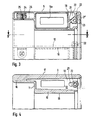
- Fig. 1 shows a showcase 1, which sits on a base 2.
- the display case has a frame, generally designated 3, which has short side walls 4 and long side walls 5. These walls are formed by profiles which are connected to one another by means of corner pieces 6.
- the base frame 2 consists of a frame-like frame, of which, however, the lower wall is not shown.
- This frame consists of short profiles 7 and long profiles 8, which are connected to one another by means of corner pieces 6 '. Extending parallel to the frame side 8 is an identical frame side, not shown, which is also connected to the vertical walls 7 via corner pieces 6 'and on which feet are located.
- corner connection on the display case 1 will be considered below with reference to FIGS. 2 to 4.
- the corner pieces 6 are molded parts, preferably die-cast parts made of aluminum.
- the cross section can be seen from FIG. 4.
- Fig. 4 shows that the corner piece is hollow overall.
- the cavity is delimited by an outer wall 9, an inner wall 10, an end wall 11 and end walls 12.
- the cavity 13 has an opening 14 opposite the narrow end wall 11, which extends from one end wall 12 to the other end wall 15.
- a wall 16 rises from the front wall 11, which can be understood as an extension of the wall 9.
- the walls 9 and 16 have a flat outer surface 17 which forms part of the peripheral surface of the frame.
- the inner wall 10 also has a flat outer surface 18.
- the walls 16 and 11 form a fold for receiving a door or a thick glass wall.
- Short pins 19 are formed on the end walls 12 and fit (see FIG. 3) into a cavity 20 of the profiles 5 and 4.
- the outer contour of the cross sections of the corner pieces and the subsequent profiles is the same, so that they merge into one another at least on the visible surfaces without a step.
- the screws 22 are arranged near the edge of the corner piece.
- a tab 24 is formed opposite each end of the corner piece, which also engages in the subsequent profile.
- a screw 25 is screwed into this tab 24, which has a countersunk head which is countersunk in the profile wall 26.
- screws 22 can first be partially screwed into the associated screw channels 23.
- the corner pieces can then be attached by pushing them sideways, the partially screwed-in screw 22 being encompassed by the slot 21.
- the connection is fixed by tightening the screw 22 and inserting the screw 25.
- the two cutting surfaces in FIG. 2 lie in different planes, namely the cutting surface appearing at the top right in a plane which, as seen in FIG. 3, is on the right and goes through the screw 22 and that in FIG appearing cutting surface in a plane which is seen on the left in FIG. 3 and passes through the screw 25.
- the end walls 12 and 15 each have openings. The opening in the end wall 15 is designated 15a.
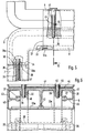
- the corner pieces 6 'of the base frame 2 have an end wall 30 at only one end, while at the other end of the corner piece a plug-in part, generally designated 31, is arranged, the cross section of which appears in FIG. 6.
- the insertion part 31 fits into the interior of the profiles 8 and merges at the joint 32 between the profile 8 and the corner piece 6 'over a step into the visible outer surfaces of the corner piece 6'.
- the corner piece 6 ' also has a lateral opening, which, however, is located here on a broad side, namely on the inside. The opening is closed with a cover 33.
- the opening itself is designated by the reference number 34.
- the insertion part has two tabs 33a at each end, which engage in the interior of the adjoining profile.
- Two wide strips 39 are integrally formed on the plug-in part 31, which on the one hand bring substantial stiffening of the plug-in part and on the other hand serve as material accumulation for achieving sufficient lengths of threaded holes 40.
- a central rib 41 is formed on the plug-in part, which engages in a groove 42, which is located inside the subsequent profile 8 is located.
- outer walls 43 Extending parallel to the central rib 41 are outer walls 43, which, however, are considerably narrower than the central rib 41. They are of such a height that they fit into the clear space between the profiled wall 44 and profiled walls 45.
- the screw channels 37 already mentioned are located at the ends of the profile walls 45.
- the corner pieces 6 ' are suitable for connecting the frame 1 to the base frame 2, which in turn is formed like a frame.
- Two screws 46 are used for the connection, which are inserted transversely through the lower profile 5 of the frame 1 and screwed into the threaded holes 40.
- a sleeve 47 is provided which absorbs the forces generated by the screw.
- the opening 34 is initially left open, so that the screw heads 36a of the screws 36 are accessible from the side.
- the insert 31 is inserted into the profile 8 with the cover 33 inserted at the same time.
- the lower profile not shown in the drawing, which is parallel to the profile 8, is also connected to the lower corner pieces 6 ', also not shown in the drawing.
Landscapes
- Engineering & Computer Science (AREA)
- Civil Engineering (AREA)
- Structural Engineering (AREA)
- General Engineering & Computer Science (AREA)
- Mechanical Engineering (AREA)
- Joining Of Corner Units Of Frames Or Wings (AREA)
- Mirrors, Picture Frames, Photograph Stands, And Related Fastening Devices (AREA)
- Devices For Indicating Variable Information By Combining Individual Elements (AREA)
- Mutual Connection Of Rods And Tubes (AREA)
- Furniture Connections (AREA)
Claims (14)
Priority Applications (1)
| Application Number | Priority Date | Filing Date | Title |
|---|---|---|---|
| AT81100476T ATE8570T1 (de) | 1980-01-31 | 1981-01-23 | Zarge fuer korpusse, insbesondere fuer vitrinen und schaukaesten. |
Applications Claiming Priority (2)
| Application Number | Priority Date | Filing Date | Title |
|---|---|---|---|
| DE8002384U | 1980-01-31 | ||
| DE19808002384U DE8002384U1 (de) | 1980-01-31 | 1980-01-31 | Zarge fuer korpusse, insbesondere fuer vitrinen und schaukaesten |
Publications (3)
| Publication Number | Publication Date |
|---|---|
| EP0033491A2 EP0033491A2 (fr) | 1981-08-12 |
| EP0033491A3 EP0033491A3 (en) | 1981-12-02 |
| EP0033491B1 true EP0033491B1 (fr) | 1984-07-25 |
Family
ID=6712440
Family Applications (1)
| Application Number | Title | Priority Date | Filing Date |
|---|---|---|---|
| EP81100476A Expired EP0033491B1 (fr) | 1980-01-31 | 1981-01-23 | Châssis pour structures, en particulier pour vitrines et meubles d'exposition |
Country Status (4)
| Country | Link |
|---|---|
| US (1) | US4396241A (fr) |
| EP (1) | EP0033491B1 (fr) |
| AT (1) | ATE8570T1 (fr) |
| DE (2) | DE8002384U1 (fr) |
Families Citing this family (4)
| Publication number | Priority date | Publication date | Assignee | Title |
|---|---|---|---|---|
| EP0097182A4 (fr) * | 1981-12-18 | 1984-05-03 | Kurt Haugen Sorensen | Assemblage de parties de mobilier. |
| DE3635108A1 (de) * | 1986-03-11 | 1987-09-17 | Nixdorf Computer Ag | Bausatz fuer moebelelemente |
| US5704699A (en) * | 1996-07-25 | 1998-01-06 | Tratec Products, Inc. | Modular cabinet system |
| DE19901775A1 (de) * | 1999-01-18 | 2000-07-20 | Schueco Int Kg | T-Verbindung zwischen einem Sprossen- und einem Pfostenprofil einer Fassade oder eines Lichtdaches |
Family Cites Families (12)
| Publication number | Priority date | Publication date | Assignee | Title |
|---|---|---|---|---|
| CA724537A (en) * | 1965-12-28 | F. Hamilton Earl | Tube construction | |
| US3044656A (en) * | 1959-08-24 | 1962-07-17 | Zero Mfg Company | Prefabricated shipping container |
| US3353863A (en) * | 1965-09-29 | 1967-11-21 | Aluminum Body Corp | Vehicle body panel construction |
| US3370521A (en) * | 1966-04-25 | 1968-02-27 | Dynamics Corp America | Ventilation enclosure structure |
| US3494686A (en) * | 1967-08-28 | 1970-02-10 | Arthur G Diack | Showcase frame |
| DE2122257A1 (de) * | 1970-05-05 | 1971-12-16 | Zanini, Luigi, Oderzo, Treviso (Italien) | Aus winkelig aneinandergrenzenden geraden Elementen gebildeter Rahmen |
| US3892189A (en) * | 1973-07-09 | 1975-07-01 | Oliver P Killam | Modular shelf construction |
| GB1464373A (en) * | 1974-01-28 | 1977-02-09 | Chadwick H | Frame kits |
| IL45572A (en) * | 1974-02-19 | 1977-01-31 | Cassel J | Connector for hollow structural elements |
| US3945743A (en) * | 1974-10-15 | 1976-03-23 | Koch Victor C | Tube fastening-joint assembly |
| GB2033526B (en) * | 1978-10-24 | 1982-04-07 | Nexus Mfg Ltd | Joints |
| US4281883A (en) * | 1979-11-19 | 1981-08-04 | Zacky Ralf G | Panel molding support structure |
-
1980
- 1980-01-31 DE DE19808002384U patent/DE8002384U1/de not_active Expired
-
1981
- 1981-01-23 EP EP81100476A patent/EP0033491B1/fr not_active Expired
- 1981-01-23 AT AT81100476T patent/ATE8570T1/de not_active IP Right Cessation
- 1981-01-23 DE DE8181100476T patent/DE3164931D1/de not_active Expired
- 1981-01-28 US US06/229,236 patent/US4396241A/en not_active Expired - Fee Related
Also Published As
| Publication number | Publication date |
|---|---|
| ATE8570T1 (de) | 1984-08-15 |
| US4396241A (en) | 1983-08-02 |
| EP0033491A2 (fr) | 1981-08-12 |
| DE8002384U1 (de) | 1980-05-08 |
| EP0033491A3 (en) | 1981-12-02 |
| DE3164931D1 (en) | 1984-08-30 |
Similar Documents
| Publication | Publication Date | Title |
|---|---|---|
| DE19932304C1 (de) | Rahmengestell für einen Schaltschrank | |
| DE3200310C2 (de) | Gestell aus mehreren Profilstäben | |
| EP0993792A1 (fr) | Arrangement de profilés pour construire des dispositions de présentation et ou de magasins | |
| DE9116213U1 (de) | Profilverbindung, insbesondere für Aluminium-Leichtbau | |
| DE3024707A1 (de) | Frachtbehaelter oder container | |
| DE3328142A1 (de) | Konstruktion aus profilstaeben | |
| DE69208989T3 (de) | Skelettprofil mit einer Zubehöranordnung | |
| EP0509206B1 (fr) | Joint droit d'un profil d'impost avec un profil de cadre ou de petits bois pour fenêtres, portes ou des choses pareilles | |
| DE69012044T2 (de) | Schublade, deren vier Seitenwände aus einem extrudierten Aluminiumprofil hergestellt sind. | |
| CH653873A5 (de) | Duschtrennwand. | |
| EP0033491B1 (fr) | Châssis pour structures, en particulier pour vitrines et meubles d'exposition | |
| DE29620153U1 (de) | Verbindung für winklig aneinanderstoßende Hohlprofilstäbe | |
| EP0371237B1 (fr) | Jeu de pièces détachées pour un châssis de porte | |
| CH420566A (de) | Doppelverglasungsrahmen für Fenster und dgl. | |
| AT7647U1 (de) | Verbindungsbeschlag für schubladen-wände | |
| DE19739394C2 (de) | Möbelkorpus | |
| EP0860575B1 (fr) | Cadre pour battants orientables de portes, fenêtres ou des choses pareilles en particulier | |
| EP2245318B1 (fr) | Noeuds d' assemblage pour éléments profilés | |
| DE3609992C2 (de) | Türzarge zur Ummantelung von Metallzargen | |
| AT394617B (de) | Fenstersprossensystem aus hohlprofilen und deren verbindungen | |
| DE8322475U1 (de) | Gestell aus Profilstäben | |
| DE20009333U1 (de) | Holzwandteil | |
| CH532185A (de) | Metalleinfassung für Fenster und Türen | |
| DE4243603A1 (de) | Verblendung für Einbaumöbelfronten | |
| EP0695849A1 (fr) | Dispositif d'assemblage d'angle pour éléments d'encadarement de fenêtres, portes ou similaires |
Legal Events
| Date | Code | Title | Description |
|---|---|---|---|
| PUAI | Public reference made under article 153(3) epc to a published international application that has entered the european phase |
Free format text: ORIGINAL CODE: 0009012 |
|
| AK | Designated contracting states |
Designated state(s): AT BE CH DE FR GB IT LI NL |
|
| PUAL | Search report despatched |
Free format text: ORIGINAL CODE: 0009013 |
|
| AK | Designated contracting states |
Designated state(s): AT BE CH DE FR GB IT LI NL |
|
| 17P | Request for examination filed |
Effective date: 19820525 |
|
| RAP1 | Party data changed (applicant data changed or rights of an application transferred) |
Owner name: WEYEL KG |
|
| ITF | It: translation for a ep patent filed | ||
| GRAA | (expected) grant |
Free format text: ORIGINAL CODE: 0009210 |
|
| AK | Designated contracting states |
Designated state(s): AT BE CH DE FR GB IT LI NL |
|
| REF | Corresponds to: |
Ref document number: 8570 Country of ref document: AT Date of ref document: 19840815 Kind code of ref document: T |
|
| REF | Corresponds to: |
Ref document number: 3164931 Country of ref document: DE Date of ref document: 19840830 |
|
| ET | Fr: translation filed | ||
| BECN | Be: change of holder's name |
Effective date: 19840725 |
|
| PLBE | No opposition filed within time limit |
Free format text: ORIGINAL CODE: 0009261 |
|
| STAA | Information on the status of an ep patent application or granted ep patent |
Free format text: STATUS: NO OPPOSITION FILED WITHIN TIME LIMIT |
|
| 26N | No opposition filed | ||
| PGFP | Annual fee paid to national office [announced via postgrant information from national office to epo] |
Ref country code: NL Payment date: 19890131 Year of fee payment: 11 |
|
| PGFP | Annual fee paid to national office [announced via postgrant information from national office to epo] |
Ref country code: CH Payment date: 19900104 Year of fee payment: 10 |
|
| PGFP | Annual fee paid to national office [announced via postgrant information from national office to epo] |
Ref country code: AT Payment date: 19900125 Year of fee payment: 10 |
|
| PGFP | Annual fee paid to national office [announced via postgrant information from national office to epo] |
Ref country code: FR Payment date: 19900130 Year of fee payment: 10 |
|
| PGFP | Annual fee paid to national office [announced via postgrant information from national office to epo] |
Ref country code: GB Payment date: 19910115 Year of fee payment: 11 |
|
| PG25 | Lapsed in a contracting state [announced via postgrant information from national office to epo] |
Ref country code: AT Effective date: 19910123 |
|
| PGFP | Annual fee paid to national office [announced via postgrant information from national office to epo] |
Ref country code: BE Payment date: 19910123 Year of fee payment: 11 |
|
| PGFP | Annual fee paid to national office [announced via postgrant information from national office to epo] |
Ref country code: DE Payment date: 19910125 Year of fee payment: 11 |
|
| ITTA | It: last paid annual fee | ||
| PG25 | Lapsed in a contracting state [announced via postgrant information from national office to epo] |
Ref country code: LI Effective date: 19910131 Ref country code: CH Effective date: 19910131 |
|
| PG25 | Lapsed in a contracting state [announced via postgrant information from national office to epo] |
Ref country code: NL Effective date: 19910801 |
|
| NLV4 | Nl: lapsed or anulled due to non-payment of the annual fee | ||
| PG25 | Lapsed in a contracting state [announced via postgrant information from national office to epo] |
Ref country code: FR Effective date: 19910930 |
|
| REG | Reference to a national code |
Ref country code: CH Ref legal event code: PL |
|
| REG | Reference to a national code |
Ref country code: FR Ref legal event code: ST |
|
| PG25 | Lapsed in a contracting state [announced via postgrant information from national office to epo] |
Ref country code: GB Effective date: 19920123 |
|
| PG25 | Lapsed in a contracting state [announced via postgrant information from national office to epo] |
Ref country code: BE Effective date: 19920131 |
|
| BERE | Be: lapsed |
Owner name: WEYEL K.G. Effective date: 19920131 |
|
| REG | Reference to a national code |
Ref country code: GB Ref legal event code: PCNP |
|
| PG25 | Lapsed in a contracting state [announced via postgrant information from national office to epo] |
Ref country code: DE Effective date: 19921001 |