EP0033525B1 - Temperaturanzeigevorrichtung an Verkehrsflächen - Google Patents
Temperaturanzeigevorrichtung an Verkehrsflächen Download PDFInfo
- Publication number
- EP0033525B1 EP0033525B1 EP81100675A EP81100675A EP0033525B1 EP 0033525 B1 EP0033525 B1 EP 0033525B1 EP 81100675 A EP81100675 A EP 81100675A EP 81100675 A EP81100675 A EP 81100675A EP 0033525 B1 EP0033525 B1 EP 0033525B1
- Authority
- EP
- European Patent Office
- Prior art keywords
- temperature
- road surface
- liquid crystal
- crystal agent
- optically
- Prior art date
- Legal status (The legal status is an assumption and is not a legal conclusion. Google has not performed a legal analysis and makes no representation as to the accuracy of the status listed.)
- Expired
Links
Images
Classifications
-
- G—PHYSICS
- G01—MEASURING; TESTING
- G01K—MEASURING TEMPERATURE; MEASURING QUANTITY OF HEAT; THERMALLY-SENSITIVE ELEMENTS NOT OTHERWISE PROVIDED FOR
- G01K1/00—Details of thermometers not specially adapted for particular types of thermometer
- G01K1/16—Special arrangements for conducting heat from the object to the sensitive element
-
- E—FIXED CONSTRUCTIONS
- E01—CONSTRUCTION OF ROADS, RAILWAYS, OR BRIDGES
- E01F—ADDITIONAL WORK, SUCH AS EQUIPPING ROADS OR THE CONSTRUCTION OF PLATFORMS, HELICOPTER LANDING STAGES, SIGNS, SNOW FENCES, OR THE LIKE
- E01F9/00—Arrangement of road signs or traffic signals; Arrangements for enforcing caution
- E01F9/40—Arrangements responsive to adverse atmospheric conditions, e.g. to signal icy roads or to automatically illuminate in fog; Arrangements characterised by heating or drying means
-
- G—PHYSICS
- G01—MEASURING; TESTING
- G01K—MEASURING TEMPERATURE; MEASURING QUANTITY OF HEAT; THERMALLY-SENSITIVE ELEMENTS NOT OTHERWISE PROVIDED FOR
- G01K11/00—Measuring temperature based upon physical or chemical changes not covered by groups G01K3/00, G01K5/00, G01K7/00 or G01K9/00
- G01K11/12—Measuring temperature based upon physical or chemical changes not covered by groups G01K3/00, G01K5/00, G01K7/00 or G01K9/00 using changes in colour, translucency or reflectance
- G01K11/16—Measuring temperature based upon physical or chemical changes not covered by groups G01K3/00, G01K5/00, G01K7/00 or G01K9/00 using changes in colour, translucency or reflectance of organic materials
- G01K11/165—Measuring temperature based upon physical or chemical changes not covered by groups G01K3/00, G01K5/00, G01K7/00 or G01K9/00 using changes in colour, translucency or reflectance of organic materials of organic liquid crystals
-
- G—PHYSICS
- G08—SIGNALLING
- G08B—SIGNALLING SYSTEMS, e.g. PERSONAL CALLING SYSTEMS; ORDER TELEGRAPHS; ALARM SYSTEMS
- G08B19/00—Alarms responsive to two or more different undesired or abnormal conditions, e.g. burglary and fire, abnormal temperature and abnormal rate of flow
- G08B19/02—Alarm responsive to formation or anticipated formation of ice
Definitions
- the invention relates to a device on a traffic area with a raised and arranged on the edge of the traffic area display member for the highly visible display of the temperature of the surface of the surface or the top layer, which by using a substance that exceeds a temperature threshold from one visually perceptible state to another such a state passes, the temperature in the vicinity of the melting point of the water indicates in such a way that it can be seen whether the temperature is above or below the temperature threshold value.
- Such a device is known from GB-PS-1 103 705.
- a liquid is used to indicate a change in temperature which, due to a change from the non-ionized to the ionized state, is intended to represent a color change in the vicinity of the zero point.
- usable liquids are not known for use in ice warning devices.
- the use of liquid also has the disadvantage that it evaporates, especially when, as proposed in the known device, carbon tetrachloride or alcohol is to be used as the solvent.
- the invention is therefore based on the object of providing a device of the type mentioned at the outset in a simple and therefore inexpensive design which reliably indicates the temperature of the covering surface or covering layer with regard to the exceeding of a threshold value without moving parts.
- a liquid crystal element is provided as the display element, which is connected by a heat conductor to the measuring point on the surface of the covering or in the top layer of the covering.
- This device works energy self-sufficiently by connecting the measuring point with the temperature display via a heat conductor. This enables a cost-effective installation in the road network.
- Liquid crystals can provide an extremely thin layer in the required temperature display. This also ensures low material consumption with low display inertia and largely avoids the risk of damage to the temperature display caused by thrown up chips.
- the device Despite the monitoring of the temperature at the desired point, namely the surface of the covering or the covering layer, the device has no moving parts and is therefore largely maintenance-free.
- Liquid crystal organs for displaying a temperature change are already known.
- US-A-4 019 368 describes an image-like room thermometer in which colored areas of the image change color when certain temperatures are exceeded.
- thermometer is provided to determine the exact temperature.
- a use in the sense of the present invention as a device on a traffic surface for displaying the temperature of the surface of the covering is not possible with the image which can be changed in color by the room temperature.
- the liquid crystal device known from DE-A-2 619 285 also only serves to display the ambient temperature.
- the device which is primarily intended as a "digital thermometer", can also be used to display temperature ranges (temperatures greater or less than 0 ° C) due to an additional fluorescent plate, but it does not give any suggestion of providing a liquid crystal organ as a display element, which can be caused by a Heat conductor is connected to the measuring location on or in the surface of the covering.
- CH-A-563 045 in which a mercury contact thermometer is provided as a display device, which has indicator lamps for certain temperature values, as a device for the early determination of the prerequisites for the formation of frost on road surfaces.
- a frost and black ice warning device is also known, which requires considerable design effort and, because of the evaporating liquid, permanent maintenance.
- this warning device the drop in temperature below freezing is to be made visible by the fact that due to the expansion of freezing water, a second colored liquid is shifted upwards so that it reaches the area of a viewing window, which is perceived from the outside as a color change.
- the substance itself does not change into an optically different state. It does not seem technically feasible to move such a large amount of a second liquid through a first freezing liquid in a device of a traffic area that a viewing window serving as a display element is covered, which is so large that it is still appropriate for a driver Distance can be perceived.
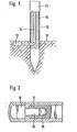
- a display post 10 has at its upper end a display element 11 pointing along the street, which consists of a liquid crystal.
- the liquid crystal is composed in such a way that it has the optically effective crystal envelope in the vicinity of the water freezing point.
- the temperature to be displayed should be that of the covering layer 12 of a road surface.
- a temperature sensor in the form of a thermally highly conductive metal body 13 is located at the measuring location, which is connected to the display element 11 by a likewise thermally well-conductive connection in the form of a heat conductor 14, which can be made of copper, for example.
- the heat conductor 14 is thermally insulated by thermal insulation 15. For reasons of assembly, the heat conductor 14 can be separated on the outer circumference of the display pole 10.
- the heat coupling is shown in Fig. 2.
- Two rods 16 and 17 made of thermally highly conductive material are plugged together in close thermal contact at the connection point.
- the contact can be improved by springs, as not shown.
- one end of the rod 17 has a bore 18 into which a pin 19 penetrates from the rod 16 closely and with good thermal contact.
- the insulation jackets belonging to these two rods 16 and 17 abut each other firmly and in an insulating manner.
Landscapes
- Physics & Mathematics (AREA)
- General Physics & Mathematics (AREA)
- Chemical & Material Sciences (AREA)
- Crystallography & Structural Chemistry (AREA)
- Life Sciences & Earth Sciences (AREA)
- Atmospheric Sciences (AREA)
- Engineering & Computer Science (AREA)
- Architecture (AREA)
- Civil Engineering (AREA)
- Structural Engineering (AREA)
- Road Signs Or Road Markings (AREA)
- Traffic Control Systems (AREA)
Description
- Die Erfindung betrifft eine Vorrichtung an einer Verkehrsfläche mit einem erhöht und am Rande der Verkehrsfläche angeordneten Anzeigeorgan zur weit sichtbaren Anzeige der Temperatur der Belagoberfläche oder der obersten Belagschicht, welche durch Verwendung einer Substanz, die bei Überschreiten eines Temperaturschwellenwertes von einem optisch wahrnehmbaren Zustand in einen anderen solchen Zustand übergeht, die Temperatur in der Umgebung des Schmelzpunktes des Wassers in der Weise anzeigt, dass erkennbar ist, ob die Temperatur oberhalb oder unterhalb des Temperaturschwellenwertes liegt.
- Eine derartige Vorrichtung ist aus der GB-PS-1 103 705 bekannt. Bei dieser Vorrichtung wird zur Anzeige eines Temperaturwechsels eine Flüssigkeit verwendet, die aufgrund eines Wechsels von nicht-ionisierten in den ionisierten Zustand eine Farbänderung in der Nähe des Nullpunktes darstellen soll. Für den Einsatz in Eiswarneinrichtungen sind solche brauchbaren Flüssigkeiten aber nicht bekannt. Die Verwendung von Flüssigkeit hat auch noch den Nachteil, dass diese verdunstet, insbesondere wenn, wie bei der bekannten Vorrichtung vorgeschlagen, Kohlenstofftetrachlorid oder Alkohol als Lösungsmittel eingesetzt werden soll. Ausserdem besteht bei der bekannten Vorrichtung die Gefahr, dass durch hochgeschleuderten Splitt die Glasabdeckung zerstört und die Flüssigkeit auslaufen kann. Bei Lösungen, die durch Farbumschlag eine Temperaturänderung anzeigen sollen, wäre ferner eine erhebliche Schichtdicke und daher ein erhebliches Flüssigkeitsvolumen erforderlich. Bei der bekannten Vorrichtung wird ausserdem die Temperatur lediglich in der Höhe der Anzeigescheibe überwacht. Damit diese aber von einem Autofahrer mit Sicherheit gesehen werden kann, muss sie in einem ausreichenden Abstand oberhalb der Strassenoberfläche angeordnet sein. Da die Lufttemperatur aber häufig erheblich von der Temperatur des Bodens und des angrenzenden Fahrbahnbelages abweicht, kann diese bekannte Vorrichtung nicht die Aufgabe einer zuverlässigen Eiswarnvorrichtung erfüllen.
- Der Erfindung liegt daher die Aufgabe zugrunde, eine Vorrichtung der eingangs genannten Art in einfacher und damit kostengünstiger Bauart zu schaffen, die ohne bewegliche Teile die Temperatur der Belagoberfläche oder Belagschicht zuverlässig hinsichtlich des Überschreitens eines Schwellenwertes anzeigt.
- Diese Aufgabe wird erfindungsgemäss dadurch gelöst, dass als Anzeigeorgan ein Flüssigkeitskristallorgan vorgesehen ist, welches durch einen Wärmeleiter mit dem Messort auf der Belagoberfläche oder in der obersten Belagschicht verbunden ist. Diese Vorrichtung arbeitet durch die Verbindung des Messortes mit der Temperaturanzeige über einen Wärmeleiter energieautark. Damit ist eine kostengünstige Aufstellung im Strassennetz möglich. Flüssigkeitskristalle können in ausserordentlich dünner Schicht schon in erforderliche Temperaturanzeige liefern. Damit ist auch ein geringer Materialverbrauch bei geringer Anzeigeträgheit gewährleistet und die Gefahr einer die Temperaturanzeige beeinträchtigenden Beschädigung durch hochgeschleuderten Splitt weitgehend vermieden. Die Vorrichtung hat trotz der Überwachung der Temperatur an der gewünschten Stelle, nämlich der Belagoberfläche oder der Belagschicht, keinerlei beweglichen Teile und ist damit weitgehend wartungsfrei.
- Flüssigkeitskristallorgane zur Anzeige eines Temperaturumschlages sind bereits bekannt. So wird in der US-A-4 019 368 ein bildartiges Raumthermometer beschrieben, bei dem farbige Flächen des Bildes bei Überschreiten bestimmter Temperaturen einen Farbumschlag durchführen.
- Zur Bestimmung der exakten Temperatur ist jedoch ein herkömmliches Zimmerthermometer vorgesehen. Eine Verwendung im Sinne der vorliegenden Erfindung als Vorrichtung an einer Verkehrsfläche zur Anzeige der Temperatur der Belagoberfläche ist mit dem durch die Raumtemperatur in seiner Farbgestaltung veränderbaren Bild nicht möglich.
- Auch die aus der DE-A-2 619 285 bekannte Flüssigkristallvorrichtung dient lediglich zur Anzeige der Umgebungstemperatur. Die in erster Linie als «Digital-Thermometer» gedachte Vorrichtung lässt sich durch eine zusätzliche Fluoreszensplatte auch zur Anzeige von Temperaturbereichen (Temperaturen grösser oder kleiner 0 °C) verwenden, sie gibt aber keine Anregung derart, als Anzeigeorgan ein Flüssigkeitskristallorgan vorzusehen, welches durch einen Wärmeleiter mit dem Messort auf oder in der Belagoberfläche verbunden ist.
- Gleiches gilt für die CH-A-563 045, bei der als Vorrichtung zur frühzeitigen Ermittlung der Voraussetzungen zur Bildung von Frostglätte auf Strassenfahrbahnen ein Quecksilberkontaktthermometer als Anzeigeorgan vorgesehen ist, das Anzeigelampen für bestimmte Temperaturwerte aufweist.
- Aus der DE-OS 2 634 579 ist ferner ein Frost-und Glatteis-Warngerät bekannt, das einen erheblichen konstruktiven Aufwand und wegen der verdunstenden Flüssigkeit eine dauernde Wartung erfordert. Bei diesem Warngerät soll das Absinken der Temperatur unter den Gefrierpunkt dadurch sichtbar gemacht werden, dass aufgrund der Ausdehnung gefrierenden Wassers eine zweite farbige Flüssigkeit soweit nach oben verschoben wird, dass sie in den Bereich eines Sichtfensters gelangt, was von aussen als Farbumschlag wahrgenommen wird. Die Substanz selbst geht nicht in einen optisch anderen Zustand über. Es erscheint technisch nicht realisierbar, eine derart grosse Menge einer zweiten Flüssigkeit durch eine erste gefrierende Flüssigkeit in einer Vorrichtung einer Verkehrsfläche soweit zu verschieben, dass dadurch ein als Anzeigeorgan dienendes Sichtfenster überstrichen wird, was so gross ist, dass es von einem Autofahrer noch in angemessenem Abstand wahrgenommen werden kann.
- Die Erfindung wird nachfolgend anhand eines Ausführungsbeispiels näher erläutert, das in der Zeichnung dargestellt ist.
- Es zeigen:
- Fig. 1 einen Teillängsschnitt einer erfindungsgemässen Vorrichtung und
- Fig. 2 in gleicher Schnittdarstellung einen vergrösserten Ausschnitt des in Fig. 1 gezeigten Anzeigepfahles im Bereich der Strassendecke.
- Eine Anzeigepfahl 10 weist an seinem oberen Ende ein längs der Strasse zeigendes Anzeigeorgan 11 auf, das aus einem Flüssigkristall besteht. Der Flüssigkristall ist so zusammengesetzt, dass er den optisch wirksamen Kristallumschlag in der Nähe des Wassergefrierpunktes hat. Die anzuzeigende Temperatur soll die der Belagschicht 12 einer Strassendecke sein. Dazu befindet sich am Messort ein Temperaturfühler in Form einer thermisch gut leitenden Metallkörpers 13, der durch eine ebenfalls thermisch ebenfalls gut leitende Verbindung in Form eines Wärmeleiters 14, der beispielsweise aus Kupfer bestehen kann, mit dem Anzeigeorgan 11 verbunden ist. Um den als Temperaturfühler dienenden Metallkörper 13 und das Anzeigeorgan 11 auf derselben Temperatur zu halten, ist der Wärmeleiter 14 thermisch durch eine Wärmeisolation 15 isoliert. Der Wärmeleiter 14 ist aus Montagegründen am Aussenumfang des Anzeigepfahles 10 auftrennbar.
- Die Wärmekupplung ist in Fig. 2 gezeigt. Dabei sind an der Verbindungsstelle zwei aus thermisch gut leitendem Werkstoff bestehende Stangen 16 und 17 in engem Wärmekontakt zusammengesteckt. Der Kontakt kann, wie nicht näher dargestellt, durch Federn verbessert werden. In dem dargestellten Ausführungsbeispiel weist das eine Ende der Stange 17 eine Bohrung 18 auf, in die von der Stange 16 her ein Zapfen 19 eng passend und mit gutem Wärmekontakt eindringt. Die zu diesen beiden Stangen 16 und 17 gehörenden lsolationsmäntel stossen fest und isolierend aneinander.
Claims (1)
Priority Applications (1)
| Application Number | Priority Date | Filing Date | Title |
|---|---|---|---|
| AT81100675T ATE34841T1 (de) | 1980-01-31 | 1981-01-30 | Temperaturanzeigevorrichtung an verkehrsflaechen. |
Applications Claiming Priority (2)
| Application Number | Priority Date | Filing Date | Title |
|---|---|---|---|
| DE3003408A DE3003408C2 (de) | 1980-01-31 | 1980-01-31 | Vorrichtung an einer Verkehrsfläche zur Anzeige der Temperatur der Belagoberfläche |
| DE3003408 | 1980-01-31 |
Publications (3)
| Publication Number | Publication Date |
|---|---|
| EP0033525A2 EP0033525A2 (de) | 1981-08-12 |
| EP0033525A3 EP0033525A3 (en) | 1983-05-25 |
| EP0033525B1 true EP0033525B1 (de) | 1988-06-01 |
Family
ID=6093344
Family Applications (1)
| Application Number | Title | Priority Date | Filing Date |
|---|---|---|---|
| EP81100675A Expired EP0033525B1 (de) | 1980-01-31 | 1981-01-30 | Temperaturanzeigevorrichtung an Verkehrsflächen |
Country Status (5)
| Country | Link |
|---|---|
| US (1) | US4419952A (de) |
| EP (1) | EP0033525B1 (de) |
| AT (1) | ATE34841T1 (de) |
| DE (1) | DE3003408C2 (de) |
| IL (1) | IL62062A (de) |
Families Citing this family (6)
| Publication number | Priority date | Publication date | Assignee | Title |
|---|---|---|---|---|
| GB2118228A (en) * | 1982-03-13 | 1983-10-26 | Edward Raymond Stevens | Hazard warning device |
| WO1984000231A1 (fr) * | 1982-06-30 | 1984-01-19 | Meier Hans Ulrich | Reflecteur de lumiere sensible a la temperature notamment avertisseur de verglas en circulation routiere |
| ATE85822T1 (de) * | 1985-07-23 | 1993-03-15 | Minnesota Mining & Mfg | Leuchtende markierungsbaender fuer verkehrsflaechen. |
| US4738549A (en) * | 1986-04-03 | 1988-04-19 | Plimpton R Gregory | Pool thermometer |
| GB2247951B (en) * | 1990-09-17 | 1994-11-09 | Cowell Ltd W S | Indicating devices in combination with plants |
| DE102005011978A1 (de) * | 2005-03-14 | 2006-09-21 | Endress & Hauser Wetzer Gmbh + Co. Kg | Vorrichtung zur Bestimmung und/oder Überwachung der Temperatur |
Citations (3)
| Publication number | Priority date | Publication date | Assignee | Title |
|---|---|---|---|---|
| GB1103705A (en) * | 1966-03-25 | 1968-02-21 | Muirhead & Co Ltd | Improvements in or relating to visual indication of temperature change |
| CH563045A5 (de) * | 1972-06-12 | 1975-06-13 | Weisser Hubert Kg | |
| DE2619285A1 (de) * | 1976-04-30 | 1977-11-10 | Siemens Ag | Fluessigkristallanzeigevorrichtung mit einer fluoreszenzplatte |
Family Cites Families (10)
| Publication number | Priority date | Publication date | Assignee | Title |
|---|---|---|---|---|
| BE546520A (de) * | ||||
| US3018663A (en) * | 1956-09-13 | 1962-01-30 | United States Steel Corp | Furnace lining temperature-thickness measuring apparatus |
| CH424309A (fr) * | 1964-02-14 | 1966-11-15 | Mourgeon Jean Claude | Dispositif pour la signalisation du verglas sur une piste de roulement, notamment sur route |
| US3422677A (en) * | 1966-06-21 | 1969-01-21 | Holley Carburetor Co | Ice condition detecting device |
| US3537315A (en) * | 1968-07-29 | 1970-11-03 | Nat Beryllia Corp | Temperature sensing device |
| FR2174946A1 (en) * | 1972-03-03 | 1973-10-19 | Firth Robertshaw Michael | Ice indicator - contg a transparent sachet filled with liquid which reflects when frozen |
| DE2514852A1 (de) * | 1975-04-04 | 1976-10-14 | Hans Beutenmueller | Doppelseitiges selbstdrehendes frostwarnschild |
| US4019368A (en) * | 1976-01-08 | 1977-04-26 | Navato Jose Miguel Antonio Ros | Pictorial room thermometer |
| DE2634579C2 (de) * | 1976-07-31 | 1983-01-27 | geb. Schuck Christel 5483 Ahrweiler Brenner | Frost- und Glatteis-Warngerät |
| DE2940205A1 (de) * | 1979-10-04 | 1981-04-16 | Karl-Gottfried Dr. 7000 Stuttgart Reinsch | Vorrichtung zum warnen vor eisglaettegefahr |
-
1980
- 1980-01-31 DE DE3003408A patent/DE3003408C2/de not_active Expired
-
1981
- 1981-01-30 AT AT81100675T patent/ATE34841T1/de not_active IP Right Cessation
- 1981-01-30 EP EP81100675A patent/EP0033525B1/de not_active Expired
- 1981-02-04 IL IL62062A patent/IL62062A/xx unknown
- 1981-02-09 US US06/233,075 patent/US4419952A/en not_active Expired - Fee Related
Patent Citations (3)
| Publication number | Priority date | Publication date | Assignee | Title |
|---|---|---|---|---|
| GB1103705A (en) * | 1966-03-25 | 1968-02-21 | Muirhead & Co Ltd | Improvements in or relating to visual indication of temperature change |
| CH563045A5 (de) * | 1972-06-12 | 1975-06-13 | Weisser Hubert Kg | |
| DE2619285A1 (de) * | 1976-04-30 | 1977-11-10 | Siemens Ag | Fluessigkristallanzeigevorrichtung mit einer fluoreszenzplatte |
Also Published As
| Publication number | Publication date |
|---|---|
| DE3003408A1 (de) | 1981-08-06 |
| IL62062A (en) | 1985-09-29 |
| EP0033525A3 (en) | 1983-05-25 |
| EP0033525A2 (de) | 1981-08-12 |
| ATE34841T1 (de) | 1988-06-15 |
| US4419952A (en) | 1983-12-13 |
| DE3003408C2 (de) | 1984-09-13 |
Similar Documents
| Publication | Publication Date | Title |
|---|---|---|
| DE10040321A1 (de) | Temperaturanzeigeeinrichtung | |
| DE69933240T2 (de) | Richtungsfahnen-drehwertgeber zur messung der windrichtung mit integrietem heizer | |
| DE60304597T2 (de) | Transparentes fenster mit nichttransparenter kontaktfläche für l t-bond-verbindung | |
| DE2350404A1 (de) | Elektrisch heizbares fenster | |
| DE8224462U1 (de) | Abschirmfolie | |
| DE3003408C2 (de) | Vorrichtung an einer Verkehrsfläche zur Anzeige der Temperatur der Belagoberfläche | |
| DE20219911U1 (de) | Temperaturanzeigeelement für ein Kältegerät | |
| DE2732395C2 (de) | ||
| DE3700076C2 (de) | ||
| DE3716766A1 (de) | Verglasungstafel | |
| DE3444171A1 (de) | Fuehlereinrichtung zum erkennen von reifniederschlaegen | |
| DE69911156T2 (de) | Glasscheibe | |
| DE2940205A1 (de) | Vorrichtung zum warnen vor eisglaettegefahr | |
| DE19610885B4 (de) | Wärmeübergangsmeßgerät | |
| CH355201A (de) | Verfahren zur Herstellung eines elektrischen Widerstandes | |
| DE69631798T2 (de) | Kalorimeterverfahren und -vorrichtung für radiator | |
| DE3003683C2 (de) | ||
| DE3232211C2 (de) | Mediumtransportleitung | |
| DE2223360C3 (de) | Ionisationsrauchfühler | |
| DE9414343U1 (de) | Glatteisfrühwarnsystem | |
| DE2922633A1 (de) | Verdampfer einer waermepumpe | |
| DE2310457A1 (de) | Anzeigeeinrichtung | |
| DE1914123C (de) | Elektrisch beheizbare Glasscheibe | |
| AT389390B (de) | Waermemengenmessgeraet | |
| DE4103784C2 (de) | Elektrostatischer Wandler |
Legal Events
| Date | Code | Title | Description |
|---|---|---|---|
| PUAI | Public reference made under article 153(3) epc to a published international application that has entered the european phase |
Free format text: ORIGINAL CODE: 0009012 |
|
| AK | Designated contracting states |
Designated state(s): AT BE CH FR GB IT LI LU NL SE |
|
| 17P | Request for examination filed |
Effective date: 19820120 |
|
| PUAL | Search report despatched |
Free format text: ORIGINAL CODE: 0009013 |
|
| AK | Designated contracting states |
Designated state(s): AT BE CH FR GB IT LI LU NL SE |
|
| GRAA | (expected) grant |
Free format text: ORIGINAL CODE: 0009210 |
|
| AK | Designated contracting states |
Kind code of ref document: B1 Designated state(s): AT BE CH FR GB IT LI LU NL SE |
|
| PG25 | Lapsed in a contracting state [announced via postgrant information from national office to epo] |
Ref country code: NL Effective date: 19880601 Ref country code: IT Free format text: LAPSE BECAUSE OF FAILURE TO SUBMIT A TRANSLATION OF THE DESCRIPTION OR TO PAY THE FEE WITHIN THE PRESCRIBED TIME-LIMIT;WARNING: LAPSES OF ITALIAN PATENTS WITH EFFECTIVE DATE BEFORE 2007 MAY HAVE OCCURRED AT ANY TIME BEFORE 2007. THE CORRECT EFFECTIVE DATE MAY BE DIFFERENT FROM THE ONE RECORDED. Effective date: 19880601 |
|
| REF | Corresponds to: |
Ref document number: 34841 Country of ref document: AT Date of ref document: 19880615 Kind code of ref document: T |
|
| PG25 | Lapsed in a contracting state [announced via postgrant information from national office to epo] |
Ref country code: SE Effective date: 19880630 |
|
| ET | Fr: translation filed | ||
| GBT | Gb: translation of ep patent filed (gb section 77(6)(a)/1977) | ||
| NLV1 | Nl: lapsed or annulled due to failure to fulfill the requirements of art. 29p and 29m of the patents act | ||
| PG25 | Lapsed in a contracting state [announced via postgrant information from national office to epo] |
Ref country code: LU Free format text: LAPSE BECAUSE OF NON-PAYMENT OF DUE FEES Effective date: 19890131 |
|
| PGFP | Annual fee paid to national office [announced via postgrant information from national office to epo] |
Ref country code: GB Payment date: 19890228 Year of fee payment: 9 |
|
| PGFP | Annual fee paid to national office [announced via postgrant information from national office to epo] |
Ref country code: BE Payment date: 19890308 Year of fee payment: 9 |
|
| PLBE | No opposition filed within time limit |
Free format text: ORIGINAL CODE: 0009261 |
|
| STAA | Information on the status of an ep patent application or granted ep patent |
Free format text: STATUS: NO OPPOSITION FILED WITHIN TIME LIMIT |
|
| 26N | No opposition filed | ||
| PGFP | Annual fee paid to national office [announced via postgrant information from national office to epo] |
Ref country code: FR Payment date: 19900129 Year of fee payment: 10 Ref country code: AT Payment date: 19900129 Year of fee payment: 10 |
|
| PG25 | Lapsed in a contracting state [announced via postgrant information from national office to epo] |
Ref country code: GB Effective date: 19900130 |
|
| PG25 | Lapsed in a contracting state [announced via postgrant information from national office to epo] |
Ref country code: BE Effective date: 19900131 |
|
| PGFP | Annual fee paid to national office [announced via postgrant information from national office to epo] |
Ref country code: CH Payment date: 19900220 Year of fee payment: 10 |
|
| BERE | Be: lapsed |
Owner name: WEILER WOLFGANG Effective date: 19900131 |
|
| GBPC | Gb: european patent ceased through non-payment of renewal fee | ||
| PG25 | Lapsed in a contracting state [announced via postgrant information from national office to epo] |
Ref country code: AT Effective date: 19910130 |
|
| PG25 | Lapsed in a contracting state [announced via postgrant information from national office to epo] |
Ref country code: LI Effective date: 19910131 Ref country code: CH Effective date: 19910131 |
|
| PG25 | Lapsed in a contracting state [announced via postgrant information from national office to epo] |
Ref country code: FR Effective date: 19910930 |
|
| REG | Reference to a national code |
Ref country code: CH Ref legal event code: PL |
|
| REG | Reference to a national code |
Ref country code: FR Ref legal event code: ST |