EP0033528A1 - Durchflussdosiergerät für Anwendung mit einem Blutentnahmeapparat - Google Patents
Durchflussdosiergerät für Anwendung mit einem Blutentnahmeapparat Download PDFInfo
- Publication number
- EP0033528A1 EP0033528A1 EP81100693A EP81100693A EP0033528A1 EP 0033528 A1 EP0033528 A1 EP 0033528A1 EP 81100693 A EP81100693 A EP 81100693A EP 81100693 A EP81100693 A EP 81100693A EP 0033528 A1 EP0033528 A1 EP 0033528A1
- Authority
- EP
- European Patent Office
- Prior art keywords
- passage member
- fluid flow
- collection container
- blood collection
- space
- Prior art date
- Legal status (The legal status is an assumption and is not a legal conclusion. Google has not performed a legal analysis and makes no representation as to the accuracy of the status listed.)
- Granted
Links
- 239000008280 blood Substances 0.000 title claims abstract description 44
- 210000004369 blood Anatomy 0.000 title claims abstract description 44
- 239000012530 fluid Substances 0.000 title claims abstract description 44
- 210000003462 vein Anatomy 0.000 claims description 17
- 230000000994 depressogenic effect Effects 0.000 claims description 4
- 210000003811 finger Anatomy 0.000 description 7
- 210000002445 nipple Anatomy 0.000 description 7
- 238000000034 method Methods 0.000 description 5
- 230000017531 blood circulation Effects 0.000 description 3
- 210000003813 thumb Anatomy 0.000 description 3
- 239000011796 hollow space material Substances 0.000 description 2
- 230000000903 blocking effect Effects 0.000 description 1
- 238000010276 construction Methods 0.000 description 1
- 230000000694 effects Effects 0.000 description 1
- 239000013536 elastomeric material Substances 0.000 description 1
- 238000004519 manufacturing process Methods 0.000 description 1
- 239000000463 material Substances 0.000 description 1
- 230000013011 mating Effects 0.000 description 1
- 239000002184 metal Substances 0.000 description 1
- 230000002093 peripheral effect Effects 0.000 description 1
- 238000003825 pressing Methods 0.000 description 1
- 238000005096 rolling process Methods 0.000 description 1
- 230000000472 traumatic effect Effects 0.000 description 1
Images
Classifications
-
- A—HUMAN NECESSITIES
- A61—MEDICAL OR VETERINARY SCIENCE; HYGIENE
- A61B—DIAGNOSIS; SURGERY; IDENTIFICATION
- A61B5/00—Measuring for diagnostic purposes; Identification of persons
- A61B5/15—Devices for taking samples of blood
- A61B5/153—Devices specially adapted for taking samples of venous or arterial blood, e.g. with syringes
- A61B5/154—Devices using pre-evacuated means
-
- A—HUMAN NECESSITIES
- A61—MEDICAL OR VETERINARY SCIENCE; HYGIENE
- A61B—DIAGNOSIS; SURGERY; IDENTIFICATION
- A61B5/00—Measuring for diagnostic purposes; Identification of persons
- A61B5/15—Devices for taking samples of blood
- A61B5/150007—Details
- A61B5/150015—Source of blood
- A61B5/15003—Source of blood for venous or arterial blood
-
- A—HUMAN NECESSITIES
- A61—MEDICAL OR VETERINARY SCIENCE; HYGIENE
- A61B—DIAGNOSIS; SURGERY; IDENTIFICATION
- A61B5/00—Measuring for diagnostic purposes; Identification of persons
- A61B5/15—Devices for taking samples of blood
- A61B5/150007—Details
- A61B5/150206—Construction or design features not otherwise provided for; manufacturing or production; packages; sterilisation of piercing element, piercing device or sampling device
- A61B5/150221—Valves
-
- A—HUMAN NECESSITIES
- A61—MEDICAL OR VETERINARY SCIENCE; HYGIENE
- A61B—DIAGNOSIS; SURGERY; IDENTIFICATION
- A61B5/00—Measuring for diagnostic purposes; Identification of persons
- A61B5/15—Devices for taking samples of blood
- A61B5/150007—Details
- A61B5/150374—Details of piercing elements or protective means for preventing accidental injuries by such piercing elements
- A61B5/150381—Design of piercing elements
- A61B5/150473—Double-ended needles, e.g. used with pre-evacuated sampling tubes
- A61B5/150496—Details of construction of hub, i.e. element used to attach the double-ended needle to a piercing device or sampling device
-
- A—HUMAN NECESSITIES
- A61—MEDICAL OR VETERINARY SCIENCE; HYGIENE
- A61B—DIAGNOSIS; SURGERY; IDENTIFICATION
- A61B5/00—Measuring for diagnostic purposes; Identification of persons
- A61B5/15—Devices for taking samples of blood
- A61B5/150007—Details
- A61B5/150946—Means for varying, regulating, indicating or limiting the speed or time of blood collection
-
- A—HUMAN NECESSITIES
- A61—MEDICAL OR VETERINARY SCIENCE; HYGIENE
- A61B—DIAGNOSIS; SURGERY; IDENTIFICATION
- A61B5/00—Measuring for diagnostic purposes; Identification of persons
- A61B5/15—Devices for taking samples of blood
- A61B5/150007—Details
- A61B5/150374—Details of piercing elements or protective means for preventing accidental injuries by such piercing elements
- A61B5/150381—Design of piercing elements
- A61B5/150389—Hollow piercing elements, e.g. canulas, needles, for piercing the skin
Definitions
- the present invention relates generally to a fluid flow control device for use with an evacuated blood collection container in the collection of blood from a patient, and more particularly, concerns a fluid flow control device for such use which is operable to control the vacuum pressure applied through a blood collecting needle cannula.
- the collection operator In the procedure of collecting blood from a patient, the collection operator generally has no effective control over the flow of blood from the patient into the evacuated blood collection container. This is due to the fact that the blood collection devices generally known and used in today's market have no provision to provide such control. Control of blood flow becomes particularly important in those instances when veins collapse or occlude the needle.
- a fluid flow control device for use with an evacuated blood collection container in the collection of blood from a patient comprises a substantially rigid body.
- a first needle cannula is connected to the body and is adapted to penetrate the vein of a patient.
- a second needle cannula is connected to the body and is adapted to penetrate a stopper in an evacuated blood collection container.
- the first and second needle cannulae are connected to the body with a space in between.
- Connecting the first and second cannulae in the intermediate space is a resilient, collapsible passage member which places the first and second cannulae in fluid communication with each other.
- the passage member contacts the body only at its ends with its central portion positioned in the space to remain free of contact with the body during use.
- the passage member is accessible to finger grip from at least two different directions to allow an operator of the device to apply pressure with the fingers to control fluid flow through the passage member.
- operable means is connected to the body for collapsing the passage member during use to control fluid flow therethrough.
- This operable means takes the place of the finger grip control associated with the previously described embodiment.
- One specific embodiment of this type includes a pivotally attached lever as the operable means, adapted to contact the passage member upon being depressed.
- Another specific embodiment of this type includes a spring-loaded actuator as the operable means adapted to contact the passage member upon being depressed.
- a further specific embodiment of this type includes a wheel device to roll against the passage member for collapsing the same during use.
- other operable elements to satisfy this function fall within the purview of this invention.
- the present invention is structurally different from any previous devices serving the function described herein, including that device described in U. S. Patent No. 3,491,748.
- the present invention is simple and straightforward to use, and can be fabricated inexpensively in line with the disposability requirements of single use needles for blood collecting procedures.
- the present invention allows its operator to effectively control the vacuum pressure being applied to the vein of the patient from the evacuated blood collection container.
- the present invention provides the operator with the ability to control the rate of fluid flow by constricting the passage through which the blood flows into the collection container.
- Other advantages of the present invention are offered as well.
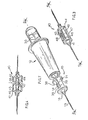
- Control device 10 assembled to a blood collection assembly 12.
- Control device 10 includes a body 14 which in the embodiment being described has a generally cylindrical shape. It is substantially rigid so that sufficient structural integrity is provided during use of this invention.
- Body 14 is formed with a hollow space 15 inside. Rigid plastic or metal are the preferred materials to be used in fabricating the body of the present device.
- a protrusion 16 which includes an internal threaded section 18.
- a first needle cannula 19 with mating threads is connected to body 14 by being threaded into protrusion 16. This feature allows different size needles to be connected to the fluid flow control device for different applications. It is appreciated that the needle cannula may be connected to body 14 by means other than the threading engagement. Needle cannula 19 is intended to penetrate a vein of a patient and is preferably connected to body 14 substantially along the longitudinal axis of the fluid flow control device.
- the opposite side of protrusion 16 includes a protruding nipple 20 within space 15 inside the hollow body.
- a hollow channel 17 extends through the protrusion/nipple portion of body 14 for a fluid path therethrough.
- At the innermost end of nipple 20 is an opening 21 so that fluid can travel through needle cannula 19 and channel 17 into the fluid flow control device.
- Needle cannula 22 is also preferably located along the longitudinal axis of control device 10 and is preferably positioned to be in substantial axial alignment with first needle cannula 19. Needle cannula 22 also terminates inside space 15 in the hollow body in a protruding nipple 24. An opening 25 is at the innermost end of nipple 24 to provide for fluid flow through needle cannula 22.
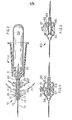
- a short protrusion 26 with external threads 28 surrounds needle cannula 22 adjacent body 14. These external threads are selected to mate with internal threads on a standard blood collection assembly 12. Included in blood collection assembly 12 is an evacuated blood collection container 30 which includes a penetrable stopper 31. As seen particularly in Fig. 2, second needle cannula 22 penetrates stopper 31 so that blood may flow into the blood collection container.
- a resilient, collapsible hollow tube 35 which serves as a passageway for the fluid to flow from needle cannula 19 to needle cannula 22.
- Tube 35 is connected only at its ends to body 14; specifically, one end of the tube is attached to nipple 20, while the other end of the tube is attached to nipple 24, thereby extending across hollow space 15 inside the body.
- the central portion of tube 35 is thus spaced sufficiently away from the walls of body 14 so as to remain free of contact with any portion of the body, particularly during use.
- hollow tube 35 be formed of an elastomeric material in order to impart the desired resilient, collapsible characteristics.
- two windows 36 are provided through the peripheral surface of body 14, the windows being substantially opposed to each other on opposite sides of tube 35 while communicating with space 15 inside the body. These windows are sufficiently large to allow the fingers F of an operator, such as indicated in Fig. 2, to reach inside of body 14 to contact tube 35.
- needle cannula 19 penetrates the vein of a patient during the blood collecting procedure. As soon as evacuated blood collection container is inserted into the collection assembly, the vacuum pressure therein causes a drawing action through both needle cannulae and the fluid flow control device. If for some reason the vein of the patient becomes collapsed or needle 19 is otherwise occluded, the present invention allows the operator to terminate the vacuum applied to needle cannula 19.
- fluid flow control device 10 may take on other configurations than those illustrated in the drawings; particularly, the axial alignment of the needle cannulae may be modified as well as the number and type of openings or windows to provide finger access inside the body of the device. For example, one large window may be provided for finger access instead of a plurality of openings.
- fluid flow control device 40 in most respects is the same as the embodiment just described, except that it includes an operable element for collapsing the resilient passage tube during use to control fluid flow therethrough.
- body 41 has at least one window opening 42 for gaining access to resilient, collapsible hollow tube 44 within.
- a depressible lever 45 is pivotally connected to body 41 by means of a pivot pin 46.
- Lever 45 has a downwardly extending depression 48 which serves as a contact surface against tube 44. In use, the operator depresses lever 45 downwardly so that depression 48 contacts tube 44 and squeezes the same.
- body 41 includes a protrusion 47 projecting upwardly toward hollow tube 44.
- Protrusion 47 is located on the body opposite from the depression on the lever so that squeezing contact is maximized.
- the operator releases depressible lever 45, the resiliency of hollow tube 44 allows it to spring back to its normal condition.
- the operator needs to use only thumb control for controlling the fluid flow through the control device.
- the fluid flow control device 50 includes a button-type actuator 51 mounted through a hole in the wall of body 52.
- a spring 54 is positioned between the wall of body 52 and a flange 55 on button actuator 51. It can be seen that downward depression of actuator 51 will cause its bottom surface 56 to come in contact with the resilient, collapsible hollow tube 58 inside body 52. This downward depression of the actuator against the hollow tube will cause it to collapse against a protrusion 57 on the wall of the body lying underneath the hollow tube.
- effective fluid flow control is provided by this embodiment.
- Fluid flow control device 60 illustrated in Fig. 6 represents another embodiment which includes an operable mechanism for collapsing the resilient passage tube within the fluid flow control device.
- a thumb wheel 61 is connected to body 62 so that by a rolling motion it will roll against resilient, collapsible passage tube 64 for collapsing same during use.
- Wheel 61 includes an off-set cam surface 63 so that, by rotation, the wheel can contact collapsible hollow tube 64 inside the body.
- a protrusion 66 on the inside wall of the bodies lies underneath the hollow tube opposite the wheel to facilitate the collapse of the tube.
- a fluid flow control device for use with an evacuated blood collection container in the collection of blood from a patient in which the operator can control the vacuum drawing force which is applied to the vein of a patient, and diminish or terminate that vacuum force by the control mechanism of this invention.
Landscapes
- Health & Medical Sciences (AREA)
- Life Sciences & Earth Sciences (AREA)
- Engineering & Computer Science (AREA)
- Heart & Thoracic Surgery (AREA)
- Molecular Biology (AREA)
- Pathology (AREA)
- Physics & Mathematics (AREA)
- Biomedical Technology (AREA)
- Hematology (AREA)
- Medical Informatics (AREA)
- Biophysics (AREA)
- Surgery (AREA)
- Animal Behavior & Ethology (AREA)
- General Health & Medical Sciences (AREA)
- Public Health (AREA)
- Veterinary Medicine (AREA)
- Manufacturing & Machinery (AREA)
- Measurement Of The Respiration, Hearing Ability, Form, And Blood Characteristics Of Living Organisms (AREA)
- Infusion, Injection, And Reservoir Apparatuses (AREA)
Applications Claiming Priority (2)
| Application Number | Priority Date | Filing Date | Title |
|---|---|---|---|
| US06/118,158 US4319582A (en) | 1980-02-04 | 1980-02-04 | Fluid flow control device for use with an evacuated blood collection container |
| US118158 | 1980-02-04 |
Publications (2)
| Publication Number | Publication Date |
|---|---|
| EP0033528A1 true EP0033528A1 (de) | 1981-08-12 |
| EP0033528B1 EP0033528B1 (de) | 1984-06-13 |
Family
ID=22376825
Family Applications (1)
| Application Number | Title | Priority Date | Filing Date |
|---|---|---|---|
| EP81100693A Expired EP0033528B1 (de) | 1980-02-04 | 1981-01-31 | Durchflussdosiergerät für Anwendung mit einem Blutentnahmeapparat |
Country Status (9)
| Country | Link |
|---|---|
| US (2) | US4319582A (de) |
| EP (1) | EP0033528B1 (de) |
| JP (1) | JPS56109643A (de) |
| AU (1) | AU535510B2 (de) |
| BR (1) | BR8008284A (de) |
| DE (1) | DE3164034D1 (de) |
| ES (1) | ES265372Y (de) |
| MX (1) | MX151668A (de) |
| NZ (1) | NZ195456A (de) |
Cited By (5)
| Publication number | Priority date | Publication date | Assignee | Title |
|---|---|---|---|---|
| WO1999048425A1 (en) * | 1998-03-25 | 1999-09-30 | The Provost, Fellows And Scholars Of The College Of The Holy And Undivided Trinity Of Queen Elizabeth Near Dublin | Sample collection device |
| US7250382B2 (en) | 2001-10-15 | 2007-07-31 | Uni-Charm Corporation | Water-disintegratable sheet and manufacturing method thereof |
| CN102596008A (zh) * | 2009-07-03 | 2012-07-18 | 瓦格纳国际股份公司 | 用于对感染或炎症进行检测和处理的系统 |
| US10265114B2 (en) | 2009-07-03 | 2019-04-23 | Levi Emmerik A. Dewaegenaere | System and method for controlling the operation of a therapeutic pad |
| EP4553479A4 (de) * | 2022-07-05 | 2026-03-18 | Blue Ind Inc | Probensammelvorrichtung und probensammelkit |
Families Citing this family (21)
| Publication number | Priority date | Publication date | Assignee | Title |
|---|---|---|---|---|
| US4509534A (en) * | 1982-06-14 | 1985-04-09 | Tassin Jr Myron J | Blood withdrawal apparatus and method of using same |
| US4548212A (en) * | 1982-10-29 | 1985-10-22 | Leung Frank K | Apparatus for thermographic examinations |
| US4685912A (en) * | 1986-03-05 | 1987-08-11 | Patent Research And Development Corp. | I.V. drip chamber with built-in pump activated by external means |
| SE462464B (sv) * | 1987-01-14 | 1990-07-02 | Broden Bengt Inge | Utrustning foer provtagning paa patienter |
| DE3733810A1 (de) * | 1987-10-07 | 1989-04-20 | Becton Dickinson Gmbh | Blutentnahmeventil |
| IL93045A (en) * | 1990-01-12 | 1995-01-24 | Rosenberg Lior | A particularly usable vacuum device for removing wound fluid |
| US5098396A (en) * | 1990-10-19 | 1992-03-24 | Taylor Ellis R | Valve for an intravascular catheter device |
| IT1297759B1 (it) * | 1997-11-13 | 1999-12-20 | Cgm Spa | Dispositivo per il prelievo di liquidi corporei e per il loro trasferimento in provette. |
| WO2003022330A2 (en) * | 2001-09-12 | 2003-03-20 | Becton, Dickinson And Company | Microneedle-based pen device for drug delivery and method for using same |
| US7842008B2 (en) | 2005-11-21 | 2010-11-30 | Becton, Dickinson And Company | Intradermal delivery device |
| US20080215014A1 (en) * | 2007-03-01 | 2008-09-04 | Greg Nordgren | Manually activated flow/no flow medical slit valves and related methods |
| ES2364733B1 (es) * | 2010-03-10 | 2012-08-03 | Biotechnology Institute, I Mas D, S.L. | Metodo para la preparacion de al menos un compuesto a partir de sangre, y dispositivo de extraccion para ser utilizado en la ejecucion de dicho metodo |
| JP6000121B2 (ja) * | 2010-03-10 | 2016-09-28 | テルモ株式会社 | 注射針組立体及び薬剤注射装置 |
| ES2394783B1 (es) * | 2010-07-16 | 2013-12-11 | Manuel FRANCISCO LOPEZ | Sistema regulador de presion negativa para la extraccion de sangre |
| WO2014058945A1 (en) | 2012-10-11 | 2014-04-17 | Bullington Gregory J | Systems and methods for delivering a fluid to a patient with reduced contamination |
| CA2911452C (en) * | 2013-05-15 | 2018-05-29 | Becton, Dickinson And Company | Vacuum pressure regulators for use during blood collection |
| WO2014185902A1 (en) | 2013-05-15 | 2014-11-20 | Becton, Dickinson And Company | Manual flow regulation for blood collection |
| WO2020146178A1 (en) * | 2019-01-07 | 2020-07-16 | Montagu Jean I | Controlling blood flow |
| US20210128037A1 (en) * | 2019-10-30 | 2021-05-06 | Becton, Dickinson And Company | Blood collection system with user-adjusted pressure management and related methods |
| US12310729B2 (en) * | 2019-11-13 | 2025-05-27 | Becton, Dickinson And Company | Blood collection system with automatic pressure management and related methods |
| US20210228125A1 (en) * | 2020-01-24 | 2021-07-29 | Becton, Dickinson And Company | Catheter having dedicated blood collection port and related methods |
Citations (1)
| Publication number | Priority date | Publication date | Assignee | Title |
|---|---|---|---|---|
| US3570484A (en) * | 1967-08-31 | 1971-03-16 | Eschmann Bros & Walsh Ltd | Intravenous valve assembly |
Family Cites Families (17)
| Publication number | Priority date | Publication date | Assignee | Title |
|---|---|---|---|---|
| US2309302A (en) * | 1941-09-08 | 1943-01-26 | Cutter Lab | Transfusion equipment |
| US2471623A (en) * | 1944-12-19 | 1949-05-31 | Adrian O Hubbell | Apparatus for handling fluids |
| US2572314A (en) * | 1947-01-27 | 1951-10-23 | Cutter Lab | Flask support and connecting member |
| US2655152A (en) * | 1951-01-30 | 1953-10-13 | Abbott Lab | Blood sampling apparatus |
| US2832344A (en) * | 1954-12-27 | 1958-04-29 | Davidson Emil | Blood sample collector |
| US3143109A (en) * | 1962-02-12 | 1964-08-04 | Raytheon Co | Blood drawing device |
| US3308809A (en) * | 1963-07-15 | 1967-03-14 | Milton J Cohen | Blood withdrawal device and dispenser |
| US3304934A (en) * | 1964-09-29 | 1967-02-21 | Dionisio O Bautista | Blood drawing device |
| US3491748A (en) * | 1967-03-20 | 1970-01-27 | Albert F Pate | Vacuum blood drawing device |
| FR1586087A (de) * | 1968-12-10 | 1970-02-06 | ||
| US3730168A (en) * | 1970-09-10 | 1973-05-01 | Kendall & Co | Manometer |
| US3874367A (en) * | 1972-06-29 | 1975-04-01 | Becton Dickinson Co | Valved blood sampling needle assembly |
| US3942514A (en) * | 1974-02-28 | 1976-03-09 | Ims Limited | Arterial blood sampling device with indicator |
| DE2543576A1 (de) * | 1975-09-30 | 1977-04-07 | Engel Joachim Michael | System zur sterilen entnahme von koerperfluessigkeiten |
| US4073288A (en) * | 1976-06-21 | 1978-02-14 | Chapman Samuel L | Blood sampling syringe |
| DE2750454C3 (de) * | 1977-11-11 | 1981-01-08 | Walter Sorstedt Kunststoff-Spritzgusswerk, 5223 Nuembrecht | Vorrichtung zur Blutentnahme |
| US4215702A (en) * | 1978-01-12 | 1980-08-05 | Patrick Ayer | Arterial blood extraction device |
-
1980
- 1980-02-04 US US06/118,158 patent/US4319582A/en not_active Expired - Lifetime
- 1980-11-05 NZ NZ195456A patent/NZ195456A/xx unknown
- 1980-12-18 BR BR8008284A patent/BR8008284A/pt not_active IP Right Cessation
- 1980-12-29 JP JP18942280A patent/JPS56109643A/ja active Pending
-
1981
- 1981-01-23 MX MX185676A patent/MX151668A/es unknown
- 1981-01-30 AU AU66756/81A patent/AU535510B2/en not_active Ceased
- 1981-01-31 DE DE8181100693T patent/DE3164034D1/de not_active Expired
- 1981-01-31 EP EP81100693A patent/EP0033528B1/de not_active Expired
- 1981-02-03 ES ES1981265372U patent/ES265372Y/es not_active Expired
- 1981-12-14 US US06/330,342 patent/US4409991A/en not_active Expired - Lifetime
Patent Citations (1)
| Publication number | Priority date | Publication date | Assignee | Title |
|---|---|---|---|---|
| US3570484A (en) * | 1967-08-31 | 1971-03-16 | Eschmann Bros & Walsh Ltd | Intravenous valve assembly |
Cited By (7)
| Publication number | Priority date | Publication date | Assignee | Title |
|---|---|---|---|---|
| WO1999048425A1 (en) * | 1998-03-25 | 1999-09-30 | The Provost, Fellows And Scholars Of The College Of The Holy And Undivided Trinity Of Queen Elizabeth Near Dublin | Sample collection device |
| US7250382B2 (en) | 2001-10-15 | 2007-07-31 | Uni-Charm Corporation | Water-disintegratable sheet and manufacturing method thereof |
| CN102596008A (zh) * | 2009-07-03 | 2012-07-18 | 瓦格纳国际股份公司 | 用于对感染或炎症进行检测和处理的系统 |
| CN102596008B (zh) * | 2009-07-03 | 2015-03-11 | 瓦格纳国际股份公司 | 用于对感染或炎症进行检测和处理的系统 |
| US9237853B2 (en) | 2009-07-03 | 2016-01-19 | Thermomend International Ltd. | System for detection and treatment of infection or inflammation |
| US10265114B2 (en) | 2009-07-03 | 2019-04-23 | Levi Emmerik A. Dewaegenaere | System and method for controlling the operation of a therapeutic pad |
| EP4553479A4 (de) * | 2022-07-05 | 2026-03-18 | Blue Ind Inc | Probensammelvorrichtung und probensammelkit |
Also Published As
| Publication number | Publication date |
|---|---|
| US4319582A (en) | 1982-03-16 |
| BR8008284A (pt) | 1981-08-04 |
| JPS56109643A (en) | 1981-08-31 |
| AU535510B2 (en) | 1984-03-22 |
| ES265372Y (es) | 1983-06-16 |
| EP0033528B1 (de) | 1984-06-13 |
| US4409991A (en) | 1983-10-18 |
| NZ195456A (en) | 1982-11-23 |
| ES265372U (es) | 1982-12-16 |
| MX151668A (es) | 1985-01-30 |
| AU6675681A (en) | 1981-08-13 |
| DE3164034D1 (en) | 1984-07-19 |
Similar Documents
| Publication | Publication Date | Title |
|---|---|---|
| US4319582A (en) | Fluid flow control device for use with an evacuated blood collection container | |
| US4307731A (en) | Multiple sampling needle having one-way valve | |
| US4108175A (en) | Catheter insertion apparatus | |
| US4456223A (en) | Flow control apparatus | |
| US6159164A (en) | Blood sampling system | |
| US3469572A (en) | Apparatus for taking multiple fluid samples | |
| US5324302A (en) | Lancet with locking cover | |
| US5680872A (en) | Simple blood-collecting device | |
| AU732501B2 (en) | Closed, one-handed blood sampling system | |
| US4106675A (en) | Liquid sampling device | |
| US8663169B2 (en) | Needle for bloodless IV | |
| US5019054A (en) | Medical device valving mechanism | |
| CA2132329C (en) | Blood sampling devices | |
| US3877465A (en) | Fluid collection device | |
| JPH0117369B2 (de) | ||
| WO2009157873A1 (en) | Haemostatic valve | |
| WO1988002082A1 (en) | Arrangement for controlling and regulating a liquid flowing through a line | |
| US5588634A (en) | Fluid flow control device pinch mechanism | |
| US4440378A (en) | Flow control apparatus | |
| US4031896A (en) | Surgical suction sets | |
| DE19846625A1 (de) | Spritze für ein Endoskop | |
| US20030039587A1 (en) | Transfer device | |
| US5057080A (en) | Medical suction tube and suction control apparatus for endoscope | |
| US2863451A (en) | Blood transfusion assembly | |
| EP0312073B1 (de) | Ansatzstück mit Ventil |
Legal Events
| Date | Code | Title | Description |
|---|---|---|---|
| PUAI | Public reference made under article 153(3) epc to a published international application that has entered the european phase |
Free format text: ORIGINAL CODE: 0009012 |
|
| AK | Designated contracting states |
Designated state(s): BE DE FR GB IT LU NL SE |
|
| 17P | Request for examination filed |
Effective date: 19810910 |
|
| ITF | It: translation for a ep patent filed | ||
| GRAA | (expected) grant |
Free format text: ORIGINAL CODE: 0009210 |
|
| AK | Designated contracting states |
Designated state(s): BE DE FR GB IT LU NL SE |
|
| REF | Corresponds to: |
Ref document number: 3164034 Country of ref document: DE Date of ref document: 19840719 |
|
| ET | Fr: translation filed | ||
| PLBE | No opposition filed within time limit |
Free format text: ORIGINAL CODE: 0009261 |
|
| STAA | Information on the status of an ep patent application or granted ep patent |
Free format text: STATUS: NO OPPOSITION FILED WITHIN TIME LIMIT |
|
| 26N | No opposition filed | ||
| ITTA | It: last paid annual fee | ||
| EPTA | Lu: last paid annual fee | ||
| EAL | Se: european patent in force in sweden |
Ref document number: 81100693.1 |
|
| PGFP | Annual fee paid to national office [announced via postgrant information from national office to epo] |
Ref country code: LU Payment date: 19971215 Year of fee payment: 18 |
|
| PGFP | Annual fee paid to national office [announced via postgrant information from national office to epo] |
Ref country code: FR Payment date: 19980109 Year of fee payment: 18 |
|
| PGFP | Annual fee paid to national office [announced via postgrant information from national office to epo] |
Ref country code: SE Payment date: 19980116 Year of fee payment: 18 |
|
| PGFP | Annual fee paid to national office [announced via postgrant information from national office to epo] |
Ref country code: GB Payment date: 19980122 Year of fee payment: 18 |
|
| PGFP | Annual fee paid to national office [announced via postgrant information from national office to epo] |
Ref country code: NL Payment date: 19980128 Year of fee payment: 18 |
|
| PGFP | Annual fee paid to national office [announced via postgrant information from national office to epo] |
Ref country code: DE Payment date: 19980206 Year of fee payment: 18 |
|
| PGFP | Annual fee paid to national office [announced via postgrant information from national office to epo] |
Ref country code: BE Payment date: 19980320 Year of fee payment: 18 |
|
| PG25 | Lapsed in a contracting state [announced via postgrant information from national office to epo] |
Ref country code: LU Free format text: LAPSE BECAUSE OF EXPIRATION OF PROTECTION Effective date: 19990131 Ref country code: GB Free format text: LAPSE BECAUSE OF NON-PAYMENT OF DUE FEES Effective date: 19990131 Ref country code: BE Free format text: LAPSE BECAUSE OF NON-PAYMENT OF DUE FEES Effective date: 19990131 |
|
| PG25 | Lapsed in a contracting state [announced via postgrant information from national office to epo] |
Ref country code: SE Free format text: LAPSE BECAUSE OF NON-PAYMENT OF DUE FEES Effective date: 19990201 |
|
| BERE | Be: lapsed |
Owner name: BECTON DICKINSON AND CY Effective date: 19990131 |
|
| PG25 | Lapsed in a contracting state [announced via postgrant information from national office to epo] |
Ref country code: NL Free format text: LAPSE BECAUSE OF NON-PAYMENT OF DUE FEES Effective date: 19990801 |
|
| GBPC | Gb: european patent ceased through non-payment of renewal fee |
Effective date: 19990131 |
|
| PG25 | Lapsed in a contracting state [announced via postgrant information from national office to epo] |
Ref country code: FR Free format text: LAPSE BECAUSE OF NON-PAYMENT OF DUE FEES Effective date: 19990930 |
|
| EUG | Se: european patent has lapsed |
Ref document number: 81100693.1 |
|
| PG25 | Lapsed in a contracting state [announced via postgrant information from national office to epo] |
Ref country code: DE Free format text: LAPSE BECAUSE OF NON-PAYMENT OF DUE FEES Effective date: 19991103 |
|
| REG | Reference to a national code |
Ref country code: FR Ref legal event code: ST |