EP0033571A1 - Hydropneumatischer Speicher - Google Patents
Hydropneumatischer Speicher Download PDFInfo
- Publication number
- EP0033571A1 EP0033571A1 EP81200097A EP81200097A EP0033571A1 EP 0033571 A1 EP0033571 A1 EP 0033571A1 EP 81200097 A EP81200097 A EP 81200097A EP 81200097 A EP81200097 A EP 81200097A EP 0033571 A1 EP0033571 A1 EP 0033571A1
- Authority
- EP
- European Patent Office
- Prior art keywords
- piston
- sealing
- resp
- sealing member
- liquid
- Prior art date
- Legal status (The legal status is an assumption and is not a legal conclusion. Google has not performed a legal analysis and makes no representation as to the accuracy of the status listed.)
- Granted
Links
Images


Classifications
-
- F—MECHANICAL ENGINEERING; LIGHTING; HEATING; WEAPONS; BLASTING
- F15—FLUID-PRESSURE ACTUATORS; HYDRAULICS OR PNEUMATICS IN GENERAL
- F15B—SYSTEMS ACTING BY MEANS OF FLUIDS IN GENERAL; FLUID-PRESSURE ACTUATORS, e.g. SERVOMOTORS; DETAILS OF FLUID-PRESSURE SYSTEMS, NOT OTHERWISE PROVIDED FOR
- F15B1/00—Installations or systems with accumulators; Supply reservoir or sump assemblies
- F15B1/02—Installations or systems with accumulators
- F15B1/04—Accumulators
- F15B1/08—Accumulators using a gas cushion; Gas charging devices; Indicators or floats therefor
- F15B1/24—Accumulators using a gas cushion; Gas charging devices; Indicators or floats therefor with rigid separating means, e.g. pistons
-
- F—MECHANICAL ENGINEERING; LIGHTING; HEATING; WEAPONS; BLASTING
- F15—FLUID-PRESSURE ACTUATORS; HYDRAULICS OR PNEUMATICS IN GENERAL
- F15B—SYSTEMS ACTING BY MEANS OF FLUIDS IN GENERAL; FLUID-PRESSURE ACTUATORS, e.g. SERVOMOTORS; DETAILS OF FLUID-PRESSURE SYSTEMS, NOT OTHERWISE PROVIDED FOR
- F15B2201/00—Accumulators
- F15B2201/20—Accumulator cushioning means
- F15B2201/205—Accumulator cushioning means using gas
-
- F—MECHANICAL ENGINEERING; LIGHTING; HEATING; WEAPONS; BLASTING
- F15—FLUID-PRESSURE ACTUATORS; HYDRAULICS OR PNEUMATICS IN GENERAL
- F15B—SYSTEMS ACTING BY MEANS OF FLUIDS IN GENERAL; FLUID-PRESSURE ACTUATORS, e.g. SERVOMOTORS; DETAILS OF FLUID-PRESSURE SYSTEMS, NOT OTHERWISE PROVIDED FOR
- F15B2201/00—Accumulators
- F15B2201/20—Accumulator cushioning means
- F15B2201/21—Accumulator cushioning means using springs
-
- F—MECHANICAL ENGINEERING; LIGHTING; HEATING; WEAPONS; BLASTING
- F15—FLUID-PRESSURE ACTUATORS; HYDRAULICS OR PNEUMATICS IN GENERAL
- F15B—SYSTEMS ACTING BY MEANS OF FLUIDS IN GENERAL; FLUID-PRESSURE ACTUATORS, e.g. SERVOMOTORS; DETAILS OF FLUID-PRESSURE SYSTEMS, NOT OTHERWISE PROVIDED FOR
- F15B2201/00—Accumulators
- F15B2201/30—Accumulator separating means
- F15B2201/31—Accumulator separating means having rigid separating means, e.g. pistons
- F15B2201/312—Sealings therefor, e.g. piston rings
-
- F—MECHANICAL ENGINEERING; LIGHTING; HEATING; WEAPONS; BLASTING
- F15—FLUID-PRESSURE ACTUATORS; HYDRAULICS OR PNEUMATICS IN GENERAL
- F15B—SYSTEMS ACTING BY MEANS OF FLUIDS IN GENERAL; FLUID-PRESSURE ACTUATORS, e.g. SERVOMOTORS; DETAILS OF FLUID-PRESSURE SYSTEMS, NOT OTHERWISE PROVIDED FOR
- F15B2201/00—Accumulators
- F15B2201/40—Constructional details of accumulators not otherwise provided for
- F15B2201/41—Liquid ports
-
- F—MECHANICAL ENGINEERING; LIGHTING; HEATING; WEAPONS; BLASTING
- F15—FLUID-PRESSURE ACTUATORS; HYDRAULICS OR PNEUMATICS IN GENERAL
- F15B—SYSTEMS ACTING BY MEANS OF FLUIDS IN GENERAL; FLUID-PRESSURE ACTUATORS, e.g. SERVOMOTORS; DETAILS OF FLUID-PRESSURE SYSTEMS, NOT OTHERWISE PROVIDED FOR
- F15B2201/00—Accumulators
- F15B2201/40—Constructional details of accumulators not otherwise provided for
- F15B2201/415—Gas ports
Definitions
- the present invention refers to a hydraulic device especially a hydropneumatic accumulator with a piston which is freely displaceable within a cylinder, said piston dividing the cylinder into a liquid and a gas chamber and which during its initial or terminal movement close to at least one of its end positions being arranged to cooperate with a second sealing member at the end wall of the liquid chamber by means of first sealing member.
- sealing rings In piston accumulators of the above mentioned kind sealing rings are used which are pressed against the sliding surface by the pressure medium at which a very good sealing is achieved, but the friction and heat release are high.
- the heat release can be so high that special cooling devices for the pressure medium are needed.
- low-friction sealings If on the other hand so called low-friction sealings are used the piston will slide easily without any considerable heat release, but the sealing effect can be insufficient especially when the piston is displaced to its initial position, i.e. when the accumulator is discharged and the piston is at the end wall of the liquid chamber.
- the object of the present invention is to provide a hydropneumatic accumulator which despite its very high sealing effect permits the piston to slide easily within the cylinder without any disturbing heat release and by that a more uniform flow of the pressure medium is achieved.
- This object of the invention is accomplished by the fact that between said first and second sealing members there is arranged a sealing acting as a nonreturn valve preventing any flow of liquid from the piston to an inlet at said end wall but permitting flow of liquid in the opposite direction and that the first sealing member is limitedly axially displaceable in relation to the piston.
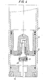
- the accumulator according to the invention comprises a cylinder 11, a piston 12 with low-friction sealings 13 and end walls 14 and 15 at the cylinder ends.
- a sealing member 20 is displaceably arranged at the piston 12, said sealing member according to the embodiment of figure 1 comprising an auxiliary piston with a friction sealing 21 in the form of a lip sealing ring having a U-shaped cross-section, the opening 22 between the lips being remote from the inlet 16,
- the first sealing member 2Q cooperates with a second sealing member 23 arranged at the inside of the end wall 14 and being designed as a short axial cylinder.
- the first sealing member 20 can be designed as a differential piston, the one smaller piston of which consists of said first sealing member, while its larger piston 24 by means of low-friction guides 25 is in close contact with the cylinder wall 26 of the accumulator.
- the piston 12 is limitedly axially displaceable along a shaft 27 connected to the first sealing member 20.
- a stop plate which in this embodiment is designed as a guiding piston 28 is arranged at the end of the shaft 27 remote from the first sealing member 20, said guiding piston 28 being provided with low-friction guides 25 in the same way as the guiding piston 24.
- FIG 1 the accumulator is shown in a discharged or alternatively preloaded state and when a pressure fluid is supplied through the inlet 16 the lips of the friction sealing 21 will let the pressure medium pass, so that it can act upon one of the end surfaces of the piston 12. As soon as the friction sealing 21 looses contact with the second sealing member 23 only low-friction sealings are active during the continued movement of the piston.
- the pressure liquid will flow past the low-friction sealings 25 of the guiding piston 24 to the part of the liquid chamber 17 which is located between the guiding piston 24 and the piston 12.
- the piston 12 is axially displaceably mounted on the shaft 27 room can be made for the displaced liquid by pressing the piston 12 towards the guiding piston 28.
- the lip sealing 21 will be exerted to a liquid pressure and owing to its function as a nonreturn valve a very good sealing is guaranteed.
- a counter pressure on the piston 12 is provided, which is advantageous if the accumulator is preloaded with e.g. nitrogen gas, said counter pressure helps separating gas from liquid.
- the embodiment shown in figure 2 differs from the one according to figure 1 by the fact that one end of the shaft 27 is designed as a first sealing member, i.e. as an auxiliary piston.
- the first sealing member is designed as an auxiliary cylinder 23, while the end wall 14, i.e. the second sealing member, is designed with a fixed piston 20.
- a sealing member 20 and/or a differential piston 20, 24 on the side of the shaft 27 located in the gas chamber 19.
- the wall 15 is designed in the same way as the end will 14.
- a by-pass passage can be arranged in the first sealing member and the differential piston resp, a nonreturn valve being arranged in said passage, said nonreturn valve permitting the liquid to flow towards the piston 12 but not in the opposite direction.
- the embodiment shown in figure 4 differs from the one according to figure 2 by the fact that the sealing member 20 is spring-loaded. Besides there is no passage through the piston 12, which means an elimination of any leakage of liquid this way.
Landscapes
- Engineering & Computer Science (AREA)
- Physics & Mathematics (AREA)
- Fluid Mechanics (AREA)
- Mechanical Engineering (AREA)
- General Engineering & Computer Science (AREA)
- Supply Devices, Intensifiers, Converters, And Telemotors (AREA)
- Bidet-Like Cleaning Device And Other Flush Toilet Accessories (AREA)
Priority Applications (1)
| Application Number | Priority Date | Filing Date | Title |
|---|---|---|---|
| AT81200097T ATE8925T1 (de) | 1980-02-04 | 1981-01-28 | Hydropneumatischer speicher. |
Applications Claiming Priority (2)
| Application Number | Priority Date | Filing Date | Title |
|---|---|---|---|
| SE8000853A SE420436B (sv) | 1980-02-04 | 1980-02-04 | Hydropneumatisk ackumulator med i en cylinder fritt forskjutbar kolv |
| SE8000853 | 1980-02-04 |
Publications (2)
| Publication Number | Publication Date |
|---|---|
| EP0033571A1 true EP0033571A1 (de) | 1981-08-12 |
| EP0033571B1 EP0033571B1 (de) | 1984-08-08 |
Family
ID=20340155
Family Applications (1)
| Application Number | Title | Priority Date | Filing Date |
|---|---|---|---|
| EP81200097A Expired EP0033571B1 (de) | 1980-02-04 | 1981-01-28 | Hydropneumatischer Speicher |
Country Status (6)
| Country | Link |
|---|---|
| US (1) | US4375227A (de) |
| EP (1) | EP0033571B1 (de) |
| JP (1) | JPS56124701A (de) |
| AT (1) | ATE8925T1 (de) |
| DE (1) | DE3165304D1 (de) |
| SE (1) | SE420436B (de) |
Cited By (1)
| Publication number | Priority date | Publication date | Assignee | Title |
|---|---|---|---|---|
| GB2143277A (en) * | 1983-06-06 | 1985-02-06 | Myrens Verksted As | Fluid accumulator |
Families Citing this family (9)
| Publication number | Priority date | Publication date | Assignee | Title |
|---|---|---|---|---|
| DE3361190D1 (en) * | 1982-02-08 | 1985-12-19 | Bolenz & Schaefer Maschf | Pressure accumulator |
| US4461322A (en) * | 1983-05-06 | 1984-07-24 | Mills Carl R | Accumulator with piston-poppet seal assembly |
| JPH0654122B2 (ja) * | 1984-03-23 | 1994-07-20 | アイシン精機株式会社 | アキユ−ムレ−タ機構 |
| GB2156435B (en) * | 1984-03-30 | 1987-09-03 | Bosch Gmbh Robert | Pressure medium accumulator |
| US6405760B1 (en) * | 2001-02-05 | 2002-06-18 | Perkinelmer, Inc. | Accumulator |
| DE10311810B3 (de) * | 2003-03-12 | 2004-12-09 | Hartmann & Lämmle GmbH & Co KG | Dämpfungseinrichtung zur Dämpfung von Unter- und/oder Überdruckstößen in Leitungen und Verfahren hierfür |
| DE102007031525B4 (de) * | 2007-07-06 | 2009-09-10 | Agco Gmbh | Kolbenspeicher zur Dämpfung von zwei Fluidsystemen |
| DE102015218624A1 (de) | 2015-09-28 | 2017-03-30 | Aktiebolaget Skf | Kolbenspeicher |
| CN110374942B (zh) * | 2019-08-29 | 2023-09-12 | 山东科技大学 | 一种大容量皮囊式恒压蓄能器及其应用 |
Family Cites Families (13)
| Publication number | Priority date | Publication date | Assignee | Title |
|---|---|---|---|---|
| FR994435A (de) * | 1951-11-23 | |||
| US2742978A (en) * | 1950-08-17 | 1956-04-24 | Stewart Warner Corp | Lubricant measuring valve for centralized lubricating system |
| US2704996A (en) * | 1952-07-17 | 1955-03-29 | Hannifin Corp | Fluid operated cylinder with adjustable cushion |
| GB755342A (en) * | 1954-03-12 | 1956-08-22 | Keelavite Co Ltd | Improvements in or relating to free piston hydraulic accumulators |
| US3043341A (en) * | 1957-07-12 | 1962-07-10 | Loewy Eng Co Ltd | Hydraulic accumulator |
| US3043340A (en) * | 1961-05-16 | 1962-07-10 | Cadillacjordan G M B H | Piston-operated pressure reservoir |
| US3148707A (en) * | 1962-03-23 | 1964-09-15 | Smyklo Alexander | Automatic hydraulic buffer |
| JPS414146Y1 (de) * | 1964-08-28 | 1966-03-12 | ||
| DE1803849A1 (de) * | 1968-10-18 | 1970-05-27 | Elmer Dipl Ing Adam | Hydrospeicher mit schwimmendem Kolben |
| US3907001A (en) * | 1973-02-12 | 1975-09-23 | Pneumo Dynamics Corp | Combination accumulator reservoir |
| JPS5420634Y2 (de) * | 1973-05-12 | 1979-07-25 | ||
| US3893486A (en) * | 1973-05-16 | 1975-07-08 | Bendix Corp | Accumulator with temperature compensation |
| US4000758A (en) * | 1974-10-21 | 1977-01-04 | Meisenheimer Jr Daniel T | Fluid reservoir device with fill means, level indicator means and pressure relief means |
-
1980
- 1980-02-04 SE SE8000853A patent/SE420436B/sv not_active IP Right Cessation
-
1981
- 1981-01-28 US US06/229,280 patent/US4375227A/en not_active Expired - Fee Related
- 1981-01-28 EP EP81200097A patent/EP0033571B1/de not_active Expired
- 1981-01-28 DE DE8181200097T patent/DE3165304D1/de not_active Expired
- 1981-01-28 AT AT81200097T patent/ATE8925T1/de not_active IP Right Cessation
- 1981-02-03 JP JP1388981A patent/JPS56124701A/ja active Pending
Cited By (1)
| Publication number | Priority date | Publication date | Assignee | Title |
|---|---|---|---|---|
| GB2143277A (en) * | 1983-06-06 | 1985-02-06 | Myrens Verksted As | Fluid accumulator |
Also Published As
| Publication number | Publication date |
|---|---|
| SE420436B (sv) | 1981-10-05 |
| SE8000853L (sv) | 1981-08-05 |
| DE3165304D1 (en) | 1984-09-13 |
| JPS56124701A (en) | 1981-09-30 |
| US4375227A (en) | 1983-03-01 |
| EP0033571B1 (de) | 1984-08-08 |
| ATE8925T1 (de) | 1984-08-15 |
Similar Documents
| Publication | Publication Date | Title |
|---|---|---|
| CA2211474C (en) | Pressure intensifier for fluids, particularly for hydraulic liquids | |
| US4597322A (en) | Seal assemblies | |
| US5377488A (en) | Hydro-pneumatic pressure transformer | |
| GB2325701A (en) | Variable-speed gas spring | |
| KR960702889A (ko) | 연속 가변형 윤활제 펌프의 다단식 조정기 | |
| KR890015895A (ko) | 완충기 | |
| EP0033571B1 (de) | Hydropneumatischer Speicher | |
| EP0125849A2 (de) | Kolbenspeicher | |
| DK370984D0 (da) | Hydraulisk styresystem til trinloest variabelt gear | |
| US2873763A (en) | Sealing means for a slidable member in a pressure unit | |
| US3467140A (en) | Hermetical sealing mechanism | |
| US3559538A (en) | Actuator | |
| GB2072886A (en) | Servo assembly | |
| US4513653A (en) | Automatic hydraulic reversing valve for a double-action working cylinder | |
| US4519413A (en) | Pressure averager | |
| US4735051A (en) | Double admitting pressure intensifier | |
| JPS5649416A (en) | Fluid slide mechanism | |
| US4543791A (en) | Power brake unit | |
| GB2115529A (en) | Directional control valve | |
| KR960011221A (ko) | 릴리이프밸브 | |
| SU1545021A1 (ru) | Предохранительный клапан | |
| JPS5481474A (en) | Fluid control system | |
| US4255092A (en) | Hydraulic variable-displacement axial piston pump having torque limitation | |
| SU1296776A1 (ru) | Импульсно-предохранительное устройство | |
| SU1717869A1 (ru) | Гидрораспределитель |
Legal Events
| Date | Code | Title | Description |
|---|---|---|---|
| PUAI | Public reference made under article 153(3) epc to a published international application that has entered the european phase |
Free format text: ORIGINAL CODE: 0009012 |
|
| AK | Designated contracting states |
Designated state(s): AT BE CH DE FR GB IT NL |
|
| 17P | Request for examination filed |
Effective date: 19811028 |
|
| GRAA | (expected) grant |
Free format text: ORIGINAL CODE: 0009210 |
|
| AK | Designated contracting states |
Designated state(s): AT BE CH DE FR GB IT LI NL |
|
| PG25 | Lapsed in a contracting state [announced via postgrant information from national office to epo] |
Ref country code: NL Effective date: 19840808 Ref country code: IT Free format text: LAPSE BECAUSE OF FAILURE TO SUBMIT A TRANSLATION OF THE DESCRIPTION OR TO PAY THE FEE WITHIN THE PRESCRIBED TIME-LIMIT;WARNING: LAPSES OF ITALIAN PATENTS WITH EFFECTIVE DATE BEFORE 2007 MAY HAVE OCCURRED AT ANY TIME BEFORE 2007. THE CORRECT EFFECTIVE DATE MAY BE DIFFERENT FROM THE ONE RECORDED. Effective date: 19840808 Ref country code: FR Free format text: THE PATENT HAS BEEN ANNULLED BY A DECISION OF A NATIONAL AUTHORITY Effective date: 19840808 Ref country code: BE Effective date: 19840808 Ref country code: AT Effective date: 19840808 |
|
| REF | Corresponds to: |
Ref document number: 8925 Country of ref document: AT Date of ref document: 19840815 Kind code of ref document: T |
|
| REF | Corresponds to: |
Ref document number: 3165304 Country of ref document: DE Date of ref document: 19840913 |
|
| NLV1 | Nl: lapsed or annulled due to failure to fulfill the requirements of art. 29p and 29m of the patents act | ||
| PGFP | Annual fee paid to national office [announced via postgrant information from national office to epo] |
Ref country code: DE Payment date: 19850325 Year of fee payment: 5 |
|
| PLBE | No opposition filed within time limit |
Free format text: ORIGINAL CODE: 0009261 |
|
| STAA | Information on the status of an ep patent application or granted ep patent |
Free format text: STATUS: NO OPPOSITION FILED WITHIN TIME LIMIT |
|
| 26N | No opposition filed | ||
| EN | Fr: translation not filed | ||
| PG25 | Lapsed in a contracting state [announced via postgrant information from national office to epo] |
Ref country code: GB Effective date: 19890128 |
|
| PG25 | Lapsed in a contracting state [announced via postgrant information from national office to epo] |
Ref country code: LI Effective date: 19890131 Ref country code: CH Effective date: 19890131 |
|
| GBPC | Gb: european patent ceased through non-payment of renewal fee | ||
| REG | Reference to a national code |
Ref country code: CH Ref legal event code: PL |
|
| PG25 | Lapsed in a contracting state [announced via postgrant information from national office to epo] |
Ref country code: DE Effective date: 19891003 |