EP0033575A2 - Mehrstufiger Entspannungsverdampfer - Google Patents
Mehrstufiger Entspannungsverdampfer Download PDFInfo
- Publication number
- EP0033575A2 EP0033575A2 EP81200121A EP81200121A EP0033575A2 EP 0033575 A2 EP0033575 A2 EP 0033575A2 EP 81200121 A EP81200121 A EP 81200121A EP 81200121 A EP81200121 A EP 81200121A EP 0033575 A2 EP0033575 A2 EP 0033575A2
- Authority
- EP
- European Patent Office
- Prior art keywords
- evaporation
- heat exchanger
- conduit
- stage
- stages
- Prior art date
- Legal status (The legal status is an assumption and is not a legal conclusion. Google has not performed a legal analysis and makes no representation as to the accuracy of the status listed.)
- Granted
Links
Images

Classifications
-
- C—CHEMISTRY; METALLURGY
- C02—TREATMENT OF WATER, WASTE WATER, SEWAGE, OR SLUDGE
- C02F—TREATMENT OF WATER, WASTE WATER, SEWAGE, OR SLUDGE
- C02F1/00—Treatment of water, waste water, or sewage
- C02F1/02—Treatment of water, waste water, or sewage by heating
- C02F1/04—Treatment of water, waste water, or sewage by heating by distillation or evaporation
- C02F1/043—Details
-
- B—PERFORMING OPERATIONS; TRANSPORTING
- B01—PHYSICAL OR CHEMICAL PROCESSES OR APPARATUS IN GENERAL
- B01D—SEPARATION
- B01D3/00—Distillation or related exchange processes in which liquids are contacted with gaseous media, e.g. stripping
- B01D3/06—Flash distillation
- B01D3/065—Multiple-effect flash distillation (more than two traps)
-
- C—CHEMISTRY; METALLURGY
- C02—TREATMENT OF WATER, WASTE WATER, SEWAGE, OR SLUDGE
- C02F—TREATMENT OF WATER, WASTE WATER, SEWAGE, OR SLUDGE
- C02F1/00—Treatment of water, waste water, or sewage
- C02F1/02—Treatment of water, waste water, or sewage by heating
- C02F1/04—Treatment of water, waste water, or sewage by heating by distillation or evaporation
- C02F1/06—Flash evaporation
Definitions
- the invention relates to a multi-stage expansion evaporator, in particular one of the type having a plurality of stages each comprising a heat exchanger compartment in open connection with an evaporation compartment, with series counterflow circulation, liquid being heated as it flows in one direction through a heat exchanger conduit, the last passing through the heat exchanger compartments and being evaporated as it flows in counterflow through the evaporation compartments.
- Multi-stage expansion evaporators have been proposed in which both heat exchangers and evaporation compartments are arranged in horizontal series, while others are proposed where the heat exchangers and evaporation compartments are arranged vertically in the direction of circulation. In the case of the latter, vertical type of evaporator, it has been proposed to maintain a fluidised granular bed within the heat exchanger tubes during operation. See Dutch Patent Application 75.05869. Although the invention relates in principle to both of these types of multi-stage expansion evaporators, it will be explained below particularly with reference to the "vertical multi-stage expansion evaporator" type with fluidised bed heat exchanger.
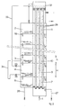
- FIG. 1 An outline diagram of a vertical evaporator with fluidised bed heat exchanger appears in Fig. 1 of the accompanying drawings.
- This apparatus is arranged like a counterflow heat exchanger.
- a pure or impure feed is supplied at point 1 at a temperature Tl and is gradually heated up to a temperature T2 on passing in series through the closed conduits of heat exchangers 7,8,9,10 and 11.
- These heat exchanger compartments are in open connection with evaporation compartments 2,3,4,5 and 6, heat exchanger 7 being connected to compartment 6, heat exchanger 8'to compartment 5, etc.
- External heat is supplied to the system by means of a heat exchanger 12 in which the feed is increased to a temperature T3 before it travels to a discharge chamber 31.
- the heated feed then flows from the discharge chamber 31 through the evaporation compartments 2 to 6 consecutively, a part of the feed evaporating in each evaporation compartment and heat being transferred to the rising feed by condensation of moisture in heat exchangers 7 to 11.
- the condensate forming in the heat exchangers is collected in troughs 13 to 17 which overflow into each other.
- the non-evaporated feed flows through permanent throttle openings 18, 19, 20 and 21, and possibly partly through variable throttle openings 22,23,24 and 25 from compartment to compartment. Flows of (a) residual feed and of (b) the condensate formed leave the system at points 26 and 27 at temperatures T4 and T5.
- the feed of such expansion evaporators commonly consists mainly of water. While reference will usually be made below to water or water vapour, the invention should be regarded as being applicable to other fluids and their vapours.
- the heat exchangers 7 to 12 comprise a number of vertical tubes 28 which are filled with particles 29.
- the particles 29 are kept fluidised.
- Various measures have been proposed to ensure that fluidisation occurs uniformly in all tubes as the feed water circulates from a distributor box 30 to the discharge chamber 31.
- the fluidised bed will drop so far down the tubes 28 that part of the heat-transferring surface of these tubes is no longer in contact with the fluidised particles 29, which is detrimental to heat transfer rates. If the feed water flows too fast in the tubes 28 the granulate will be rinsed out of the discharge chamber 31.
- variable throttle openings 18 to 21 are provided in addition to variable throttle openings 22 to 25 in at least some of the partition walls between the compartments 2 to 6 (see Fig. 1).
- the closing mechanisms of the variable throttle openings can be coupled for driving to an adjusting mechanism which can be moved from outside the evaporator. With an increasing number of evaporator compartments, these coupled closing mechanisms can lead to the apparatus becoming complicated. In practice, 30 to 40 evaporator compartments linked in series have already been adopted, and this number can be expected to increase yet further in the future.
- the object of the invention is to achieve sufficient control of the fluid level in the evaporation compartments of a multi-stage expansion evaporator, in a simple structure.
- the invention consists of a circulation conduit from the discharge chamber, provided with a control valve and connected to one of the last of the evaporation compartments in the circulation sequence.
- a circulation conduit from the discharge chamber, provided with a control valve and connected to one of the last of the evaporation compartments in the circulation sequence.
- one of the last of the evaporation compartments is meant one of the evaporation compartments in the second half of the evaporator (in the direction of flow of the liquid through the evaporation compartments), and preferably this selected compartment is among the last 30% or even 20% of the compartments.
- USA patent no. 3,329,583 describes a multi-stage evaporator in which a by-pass line can convey a proportion of the feed from the top of the heat exchanger column directly to an intermediate evaporation compartment.
- the arrangement shown differs from the present invention (a) in that the feed is drawn off prior to application of external heat (i.e. before the discharge chamber of the present invention) (b) in that the evaporation chamber to which the feed is taken by this by-pass line is not one of the last evaporation chambers and (c) in that the purpose of the use of the by-pass line is to achieve more efficient utilization of heat.
- the invention can be applied to multi-stage expansion evaporators generally, it has been found that the best results can be obtained with the invention by applying it to apparatus in which the heat exchangers and evaporation compartments are each located vertically above each other in series, and in which the heat exchangers comprise tubes filled with fluidisable particles.
- the circulation conduit of the invention need not necessarily be linked to the lowest evaporation compartment. If the liquid levels of compartments located lower permit, the circulation conduit can be connected to a compartment located above the lowermost. In a given situation, the liquid levels can then be distributed to best effect by means of the control valve in the circulation conduit. If satisfactory controllability cannot be achieved in this way, it is also possible for several circulation conduits to be connected to various evaporation compartments through separate control valves. This will generally produce more favourable energy consumption in the installation. A similar effect can also be obtained if several circulation conduits are connected by a common main conduit to the water discharge chamber.
- circulation conduits do not restrict the structural height of the evaporation compartments.
- the proposed apparatus with circulation conduit and control valve can be built up from standard elements, which produces a structurally simpler and, above all, cheaper approach, even if the number of evaporation compartments is very high.
- this will mean a greater structural height of the heat exchanger and evaporation compartment involved. By this measure, the pressure in this evaporation compartment can be lower..
- Another possible way of preventing an excessive liquid level in the preceding evaporation compartment consists in fitting a secondary circulation pipe between the evaporation compartment to which a circulation conduit is connected and the preceding evaporation compartment in the direction of flow of the evaporating liquid.
- This secondary circulation pipe can be in the form of a syphon. The length needed for this syphon can be reduced by fitting a control valve in the secondary circulation conduit.
- the secondary circulation conduit may not be a syphon, but can be equipped only with a control valve.
- This secondary circulation pipe can be fitted either at the outside or inside of the apparatus.
- FIg. 2 shows the same apparatus as Fig. 1, corresponding reference numbers relating to corresponding structural elements.
- the variable throttle openings 22 to 25 are omitted from the structure of Fig. 2.
- a circulation pipe 32 is fitted between the discharge chamber 31 and evaporation compartment 4, and contains a control valve 33.
- Compartment 4 is, as illustrated, the penultimate compartment in the sequence, but in practice there will usually be many more stages and the compartment selected for connection of the circulation conduit may be another one.
- the height H of the heat exchanger 9 and the evaporation compartment 4 is greater than the height h of the adjoining heat exchanger and evaporation compartment 10 and 3 which have a height h. This prevents the liquid level in evaporation compartment 3 from rising too high, as discussed above.
- the level in evaporation compartment 3 can also be controlled by means of a secondary circulation pipe 34 between compartments 3 and 4.
- This secondary circulation pipe can take the form of a syphon (as drawn), and a control valve 35 can also be fitted to it. It should be noted that it is, of course, possible for the circulation pipe 34 not to be in syphon form and to have only a control valve 35 fitted in it, while these measures may, further, be combined separately or jointly with a difference in height between compartments 3 and 4.
Landscapes
- Chemical & Material Sciences (AREA)
- Life Sciences & Earth Sciences (AREA)
- Hydrology & Water Resources (AREA)
- Engineering & Computer Science (AREA)
- Environmental & Geological Engineering (AREA)
- Water Supply & Treatment (AREA)
- Organic Chemistry (AREA)
- Chemical Kinetics & Catalysis (AREA)
- Heat-Exchange Devices With Radiators And Conduit Assemblies (AREA)
- Vaporization, Distillation, Condensation, Sublimation, And Cold Traps (AREA)
Applications Claiming Priority (2)
| Application Number | Priority Date | Filing Date | Title |
|---|---|---|---|
| NL8000704 | 1980-02-05 | ||
| NL8000704A NL8000704A (nl) | 1980-02-05 | 1980-02-05 | Meertraps ontspanverdamper. |
Publications (3)
| Publication Number | Publication Date |
|---|---|
| EP0033575A2 true EP0033575A2 (de) | 1981-08-12 |
| EP0033575A3 EP0033575A3 (en) | 1981-08-19 |
| EP0033575B1 EP0033575B1 (de) | 1983-09-21 |
Family
ID=19834780
Family Applications (1)
| Application Number | Title | Priority Date | Filing Date |
|---|---|---|---|
| EP19810200121 Expired EP0033575B1 (de) | 1980-02-05 | 1981-01-29 | Mehrstufiger Entspannungsverdampfer |
Country Status (4)
| Country | Link |
|---|---|
| EP (1) | EP0033575B1 (de) |
| JP (1) | JPS56126404A (de) |
| DE (1) | DE3160898D1 (de) |
| NL (1) | NL8000704A (de) |
Cited By (3)
| Publication number | Priority date | Publication date | Assignee | Title |
|---|---|---|---|---|
| FR2527089A1 (fr) * | 1982-05-24 | 1983-11-25 | Dvt Buro Anwendung Deutscher V | Procede pour la distillation d'eau douce a partir d'eau de mer ainsi que dispositif pour la mise en oeuvre de ce procede |
| FR2527091A1 (fr) * | 1982-05-24 | 1983-11-25 | Dvt Buro Anwendung Deutscher V | Support pour loger de facon etanche a la pression, une colonne garnie |
| FR2542439A1 (fr) * | 1983-03-11 | 1984-09-14 | Laguilharre Sa | Procede pour chauffer un fluide au moyen d'un liquide plus chaud et installation pour sa mise en oeuvre |
Family Cites Families (3)
| Publication number | Priority date | Publication date | Assignee | Title |
|---|---|---|---|---|
| US3329583A (en) * | 1963-01-18 | 1967-07-04 | Donald F Othmer | Method for producing pure water from sea water and other solutions by flash vaporization and condensation |
| BE679476A (de) * | 1966-04-13 | 1966-09-16 | ||
| NL175969C (nl) * | 1975-05-20 | 1985-02-01 | Ir Gustav Adolf Pieper | Verticale meertraps ontspanverdamper. |
-
1980
- 1980-02-05 NL NL8000704A patent/NL8000704A/nl not_active Application Discontinuation
-
1981
- 1981-01-29 EP EP19810200121 patent/EP0033575B1/de not_active Expired
- 1981-01-29 DE DE8181200121T patent/DE3160898D1/de not_active Expired
- 1981-02-05 JP JP1511081A patent/JPS56126404A/ja active Granted
Cited By (3)
| Publication number | Priority date | Publication date | Assignee | Title |
|---|---|---|---|---|
| FR2527089A1 (fr) * | 1982-05-24 | 1983-11-25 | Dvt Buro Anwendung Deutscher V | Procede pour la distillation d'eau douce a partir d'eau de mer ainsi que dispositif pour la mise en oeuvre de ce procede |
| FR2527091A1 (fr) * | 1982-05-24 | 1983-11-25 | Dvt Buro Anwendung Deutscher V | Support pour loger de facon etanche a la pression, une colonne garnie |
| FR2542439A1 (fr) * | 1983-03-11 | 1984-09-14 | Laguilharre Sa | Procede pour chauffer un fluide au moyen d'un liquide plus chaud et installation pour sa mise en oeuvre |
Also Published As
| Publication number | Publication date |
|---|---|
| JPS6243721B2 (de) | 1987-09-16 |
| NL8000704A (nl) | 1981-09-01 |
| JPS56126404A (en) | 1981-10-03 |
| DE3160898D1 (en) | 1983-10-27 |
| EP0033575B1 (de) | 1983-09-21 |
| EP0033575A3 (en) | 1981-08-19 |
Similar Documents
| Publication | Publication Date | Title |
|---|---|---|
| US3219554A (en) | Flash distillation apparatus with direct contact heat exchange | |
| US3303106A (en) | Falling film evaporator | |
| US4745965A (en) | Separate type heat exchanger | |
| US4928753A (en) | Heat exchanger | |
| US4953607A (en) | Multistage evaporating system | |
| KR100429017B1 (ko) | 다중효용농축 시스템 및 방법 | |
| US3590912A (en) | Vertical staggered surface feedwater heater | |
| EP0033575B1 (de) | Mehrstufiger Entspannungsverdampfer | |
| JPS5816117B2 (ja) | 複数流体間の熱交換方法 | |
| NO143984B (no) | Fremgangsmaate og anordning for inndamping av vaesker | |
| US3356125A (en) | Feeding and liquid by-passing method for falling film, multiple effect evaporators | |
| US5542267A (en) | Absorption heating and cooling device | |
| US4349068A (en) | Method for improved heat transfer | |
| US4292135A (en) | Multistage-expansion evaporator | |
| JPS6111580A (ja) | 露点冷却器 | |
| RU96110288A (ru) | Теплообменник для теплообмена между кипятильником и абсорбером, способ теплообмена и применение его в тепловом насосе | |
| KR0151937B1 (ko) | 폐액처리용 다중효용단관식 증발방법 및 장치 | |
| EP4585871A1 (de) | Generator | |
| MXPA97004052A (es) | Mezcla y dispositivo para separar una sustancia deuna mezcla de liquidos mediante cristalizacion fraccional. | |
| US4256536A (en) | Evaporator | |
| US1582066A (en) | Process of and apparatus for multiple-effect evaporative separation | |
| JPS6080089A (ja) | 多段式セパレ−ト型熱交換装置の交換熱量制御方法 | |
| KR200303111Y1 (ko) | 다중효용농축 시스템 | |
| US2570211A (en) | Falling film evaporator | |
| US2993844A (en) | Multi-stage flash evaporator |
Legal Events
| Date | Code | Title | Description |
|---|---|---|---|
| PUAI | Public reference made under article 153(3) epc to a published international application that has entered the european phase |
Free format text: ORIGINAL CODE: 0009012 |
|
| PUAL | Search report despatched |
Free format text: ORIGINAL CODE: 0009013 |
|
| 17P | Request for examination filed |
Effective date: 19810129 |
|
| AK | Designated contracting states |
Designated state(s): DE FR GB IT |
|
| AK | Designated contracting states |
Designated state(s): DE FR GB IT |
|
| ITF | It: translation for a ep patent filed | ||
| GRAA | (expected) grant |
Free format text: ORIGINAL CODE: 0009210 |
|
| AK | Designated contracting states |
Designated state(s): DE FR GB IT |
|
| REF | Corresponds to: |
Ref document number: 3160898 Country of ref document: DE Date of ref document: 19831027 |
|
| ET | Fr: translation filed | ||
| PLBE | No opposition filed within time limit |
Free format text: ORIGINAL CODE: 0009261 |
|
| STAA | Information on the status of an ep patent application or granted ep patent |
Free format text: STATUS: NO OPPOSITION FILED WITHIN TIME LIMIT |
|
| 26N | No opposition filed | ||
| ITTA | It: last paid annual fee | ||
| PGFP | Annual fee paid to national office [announced via postgrant information from national office to epo] |
Ref country code: FR Payment date: 19901210 Year of fee payment: 11 |
|
| PGFP | Annual fee paid to national office [announced via postgrant information from national office to epo] |
Ref country code: GB Payment date: 19901212 Year of fee payment: 11 |
|
| PGFP | Annual fee paid to national office [announced via postgrant information from national office to epo] |
Ref country code: DE Payment date: 19901231 Year of fee payment: 11 |
|
| PG25 | Lapsed in a contracting state [announced via postgrant information from national office to epo] |
Ref country code: GB Effective date: 19920129 |
|
| GBPC | Gb: european patent ceased through non-payment of renewal fee | ||
| PG25 | Lapsed in a contracting state [announced via postgrant information from national office to epo] |
Ref country code: FR Effective date: 19920930 |
|
| PG25 | Lapsed in a contracting state [announced via postgrant information from national office to epo] |
Ref country code: DE Effective date: 19921001 |
|
| REG | Reference to a national code |
Ref country code: FR Ref legal event code: ST |