EP0033683A2 - Dispositif solaire mixte photovoltaique et photothermique - Google Patents
Dispositif solaire mixte photovoltaique et photothermique Download PDFInfo
- Publication number
- EP0033683A2 EP0033683A2 EP81400099A EP81400099A EP0033683A2 EP 0033683 A2 EP0033683 A2 EP 0033683A2 EP 81400099 A EP81400099 A EP 81400099A EP 81400099 A EP81400099 A EP 81400099A EP 0033683 A2 EP0033683 A2 EP 0033683A2
- Authority
- EP
- European Patent Office
- Prior art keywords
- fluid
- cell
- assembly
- photovoltaic
- radiator
- Prior art date
- Legal status (The legal status is an assumption and is not a legal conclusion. Google has not performed a legal analysis and makes no representation as to the accuracy of the status listed.)
- Withdrawn
Links
Images
Classifications
-
- H—ELECTRICITY
- H10—SEMICONDUCTOR DEVICES; ELECTRIC SOLID-STATE DEVICES NOT OTHERWISE PROVIDED FOR
- H10F—INORGANIC SEMICONDUCTOR DEVICES SENSITIVE TO INFRARED RADIATION, LIGHT, ELECTROMAGNETIC RADIATION OF SHORTER WAVELENGTH OR CORPUSCULAR RADIATION
- H10F77/00—Constructional details of devices covered by this subclass
- H10F77/60—Arrangements for cooling, heating, ventilating or compensating for temperature fluctuations
- H10F77/63—Arrangements for cooling directly associated or integrated with photovoltaic cells, e.g. heat sinks directly associated with the photovoltaic cells or integrated Peltier elements for active cooling
- H10F77/68—Arrangements for cooling directly associated or integrated with photovoltaic cells, e.g. heat sinks directly associated with the photovoltaic cells or integrated Peltier elements for active cooling using gaseous or liquid coolants, e.g. air flow ventilation or water circulation
-
- H—ELECTRICITY
- H02—GENERATION; CONVERSION OR DISTRIBUTION OF ELECTRIC POWER
- H02S—GENERATION OF ELECTRIC POWER BY CONVERSION OF INFRARED RADIATION, VISIBLE LIGHT OR ULTRAVIOLET LIGHT, e.g. USING PHOTOVOLTAIC [PV] MODULES
- H02S40/00—Components or accessories in combination with PV modules, not provided for in groups H02S10/00 - H02S30/00
- H02S40/40—Thermal components
- H02S40/44—Means to utilise heat energy, e.g. hybrid systems producing warm water and electricity at the same time
-
- F—MECHANICAL ENGINEERING; LIGHTING; HEATING; WEAPONS; BLASTING
- F24—HEATING; RANGES; VENTILATING
- F24S—SOLAR HEAT COLLECTORS; SOLAR HEAT SYSTEMS
- F24S20/00—Solar heat collectors specially adapted for particular uses or environments
- F24S2020/10—Solar modules layout; Modular arrangements
- F24S2020/17—Arrangements of solar thermal modules combined with solar PV modules
-
- Y—GENERAL TAGGING OF NEW TECHNOLOGICAL DEVELOPMENTS; GENERAL TAGGING OF CROSS-SECTIONAL TECHNOLOGIES SPANNING OVER SEVERAL SECTIONS OF THE IPC; TECHNICAL SUBJECTS COVERED BY FORMER USPC CROSS-REFERENCE ART COLLECTIONS [XRACs] AND DIGESTS
- Y02—TECHNOLOGIES OR APPLICATIONS FOR MITIGATION OR ADAPTATION AGAINST CLIMATE CHANGE
- Y02E—REDUCTION OF GREENHOUSE GAS [GHG] EMISSIONS, RELATED TO ENERGY GENERATION, TRANSMISSION OR DISTRIBUTION
- Y02E10/00—Energy generation through renewable energy sources
- Y02E10/50—Photovoltaic [PV] energy
-
- Y—GENERAL TAGGING OF NEW TECHNOLOGICAL DEVELOPMENTS; GENERAL TAGGING OF CROSS-SECTIONAL TECHNOLOGIES SPANNING OVER SEVERAL SECTIONS OF THE IPC; TECHNICAL SUBJECTS COVERED BY FORMER USPC CROSS-REFERENCE ART COLLECTIONS [XRACs] AND DIGESTS
- Y02—TECHNOLOGIES OR APPLICATIONS FOR MITIGATION OR ADAPTATION AGAINST CLIMATE CHANGE
- Y02E—REDUCTION OF GREENHOUSE GAS [GHG] EMISSIONS, RELATED TO ENERGY GENERATION, TRANSMISSION OR DISTRIBUTION
- Y02E10/00—Energy generation through renewable energy sources
- Y02E10/60—Thermal-PV hybrids
Definitions
- the present invention relates to a method of cooling a solar cell and a mixed photovoltaic and photothermal solar device.
- an object of the present invention is to provide a method and a device improving the cooling of a photovoltaic device.
- Another object of the present invention is to provide such a device making it possible to supply thermal energy at a temperature higher than the temperature directly compatible with a semiconductor cell of a given type.
- the present invention provides a method of cooling a photovoltaic cell integral with a fluid circulation radiator according to which there is, in front of the cell and in the path of the incident radiation, an assembly crossed by the cooling fluid and absorbing at least part of the incident radiation, the spectrum of which is outside the sensitivity zone of the cell.
- This assembly may include transparent windows between which the fluid circulates, the materials constituting the windows and the fluid being chosen so that at least part of the radiation absorbed is directly by the fluid.
- a mixed photovoltaic and photothermal solar device with concentrated light comprises a photovoltaic cell integral with a radiator in which a cooling fluid circulates; an assembly arranged in the path of the incident beam; means for circulating the fluid in this assembly; this assembly absorbing, in cooperation with the fluid, at least part of the incident radiation located outside the response spectral band of the photovoltaic cell and transmitting the calories collected to the cooling fluid.
- the assembly in question comprises transparent windows, for example made of quartz, between which circulates the cooling fluid, for example water.
- the incident light can be focused on the coolant and slightly defocused at the level of the photovoltaic cell.
- This cell can be of the vertical multijunction silicon cell type.
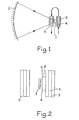
- FIG. 1 schematically represents a photovoltaic cell 1 to which a concentrated light beam is transmitted from a reflector 2.
- This cell is thermally integral with a radiator 3 in which a fluid 4 circulates.
- This fluid 4 can for example to be water. If the water entering the radiator 3 is at a temperature substantially equal to 20 ° C., it is desirable for the proper functioning of the device and the increase in the efficiency of the solar cell 1, that the outlet temperature remains low, by example not higher than 50 or 60 ° C. This temperature does not allow simple direct use of the thermal energy collected.
- auxiliary assembly 5 consisting of two transparent windows between which circulates the fluid 4 leaving the radiator 3.
- the material constituting the windows of the cell 5 as well as the fluid 4 are chosen to have particular optical absorption qualities, namely that they absorb most of the incident spectrum outside the response spectrum of photovoltaic cell 1.
- the fluid leaves the radiator 3 at a temperature between 50 and 60 ° C, it can leave the assembly 5 at a temperature of the order of 70 to 80 ° C, which makes it more directly usable for various thermal applications.
- the fluid may be water possibly added with a particular agent to absorb wavelengths greater than 1.1 microns. If you don't want the set 5 to absorb ultraviolet radiation, you can choose quartz windows for this set.
- the solar cell 1 will preferably be linked to the radiator or water bar 3 via a thermally conductive support 6.
- the light concentrated on the cell 1 has been represented. It may be preferable to concentrate the light beam coming from the reflector 2 at the level of the parasitic radiation absorption assembly 5, the light being defocused at the level of the cell. 1.
- This cell 1 can in particular be of the vertical multijunction silicon cell type, as described in particular in the article by B.L. Sater et al published in the work entitled "Solar Cells" edited by C.E. Backus at I.E.E.E. Press in 1976, pages 311 to 316.
Landscapes
- Photovoltaic Devices (AREA)
Abstract
La présente invention concerne un procédé de refroidissement de cellule solaire.
Le dispositif mettant en oeuvre ce procédé comprend un ensemble transparent 5 disposé devant une cellule photovoltaïque 1. L'ensemble transparent 5, qui est traversé par le fluide de refroidissement 4 sortant d'un radiateur 3 solidaire de la cellule, absorbe les longueurs d'onde supérieures à 1, 1 micron. Ainsi, l'échauffement de la cellule est limité et le fluide sortant du radiateur 3 est rechauffé par le faisceau frappant la cellule 5.
Application à un dispositif solaire mixte photovoltaïque et photothermique.
Description
- La présente invention concerne un procédé de refroidissement d'une cellule solaire et un dispositif solaire mixte photovoltalque et photothermique.
- On s'intéressera ici plus particulièrement aux dispositifs photovoltaiques destinés à servir de cellule solaire et fonctionnant en lumière concentrée. Le rendement de ces dispositifs est optimal quand leur température est faible. Notamment, dans le cas de cellules au silicium, il est souhaitable que la température ne dépasse pas une valeur de l'ordre de 50 à 60°C. Ainsi, de façon courante, on dispose les cellules solaires sur des radiateurs, éventuellement des radiateurs à circulation de fluide. La circulation de fluide doit être prévue de sorte que la température de sortie du fluide ne dépasse pas une valeur de l'ordre de 50 à 60°C. Un fluide à une telle température est difficilement utilisable pour des applications thermiques.
- Ainsi, un objet de la présente invention est de prévoir un procédé et un dispositif améliorant le refroidissement d'un dispositif photovoltaique.
- Un autre objet de la présente invention est de prévoir un tel dispositif permettant de fournir de l'énergie thermique à une température plus élevée que la température directement compatible avec une cellule semiconductrice de type donné.
- Pour atteindre ces objets ainsi que d'autres, la présente invention prévoit un procédé de refroidissement d'une cellule photovoltaique solidaire d'un radiateur à circulation de fluide selon lequel on dispose, devant la cellule et dans le trajet du rayonnement incident, un ensemble traversé par le fluide de refroidissement et absorbant au moins une partie du rayonnement incident dont le spectre se trouve en dehors de la zone de sensibilité de la cellule. Cet ensemble peut comprendre des fenêtres transparentes entre lesquelles circule le fluide, les matériaux constitutifs des fenêtres et du fluide étant choisis pour qu'au moins une partie du rayonnement absorbé le soit directement par le fluide.
- Un dispositif solaire mixte photovoltalque et photothermique à lumière concentrée selon la présente invention comprend une cellule photovoltalque solidaire d'un radiateur dans lequel circule un fluide de refroidissement; un ensemble disposé dans le trajet du faisceau incident; des moyens pour faire circuler le fluide dans cet ensemble; cet ensemble absorbant, en coopération avec le fluide, une partie au moins du rayonnement incident situé hors de la bande spectrale de réponse de la cellule photovoltalque et transmettant les calories recueillies au fluide de refroidissement. L'ensemble en question comprend des fenêtres transparentes, par exemple en quartz, entre lesquelles circule le fluide de refroidissement, par exemple de l'eau. La lumière incidente peut être focalisée sur le fluide de refroidissement et légèrement défocalisée au niveau de la cellule photovoltalque. Cette cellule peut être du type cellule au silicium à multijonctions verticales.
- Ces objets, caractéristiques et avantages ainsi que d'autres de la présente invention seront exposés plus en détail dans la description suivante de modes de réalisation particuliers faite en relation avec les figures jointes parmi lesquelles :
- - la figure 1 représente un dispositif selon la présente invention; et
- - la figure 2 représente de façon plus détaillée une partie de la figure 1.
- La figure 1 représente de façon schématique une cellule photovoltaique 1 vers laquelle est transmis un faisceau lumineux concentré en provenance d'un réflecteur 2. Cette cellule est solidaire thermiquement d'un radiateur 3 dans lequel circule un fluide 4. Ce fluide 4 peut par exemple être de l'eau. Si l'eau entrant dans le radiateur 3 est à une température sensiblement égale à 20°C, il est souhaitable pour le bon fonctionnement du dispositif et l'accroissement du rendement de la cellule solaire 1, que la température de sortie reste faible, par exemple non supérieure à 50 ou 60°C. Cette température ne permet pas l'utilisation directe simple de l'énergie thermique recueillie.
- Ainsi, selon la présente invention, il est prévu de disposer un ensemble auxiliaire 5 constitué de deux fenêtres transparentes entre lesquelles circule le fluide 4 sortant du radiateur 3. Le matériau constitutif des fenêtres de la cellule 5 ainsi que le fluide 4 sont choisis pour présenter des qualités d'absorption optique particulières à savoir qu'ils absorbent la plus grande partie du spectre incident se trouvant à l'extérieur du spectre de réponse de la cellule photovoltalque 1.
- 6n obtient ainsi le double avantage d'une part de limiter l'échauffement de la cellule 1 en évitant de l'irradier par des rayonnements de longueurs d'ondes ne produisant pas d'effet photovoltaïque, d'autre part d'augmenter la température du fluide à la sortie du dispositif. Ainsi, si le fluide sort du radiateur 3 à une température comprise entre 50 et 60°C, il pourra sortir de l'ensemble 5 à une température de l'ordre de 70 à 80°C, ce qui le rend plus directement utilisable pour diverses applications thermiques. Notamment, le fluide pourra être de l'eau éventuellement additionnée d'un agent particulier pour absorber les longueurs d'ondes supérieures a 1,1 micron. Si l'on ne veut pas que l'ensemble 5 absorbe les rayonnements ultraviolets, on pourra choisir pour cet ensemble des fenêtres en quartz.
- Comme le montre la figure 2, la cellule solaire 1 sera de préférence liée au radiateur ou barre à eau 3 par l'intermédiaire d'un support thermiquement conducteur 6.
- En figure 1, on a représenté la lumière concentrée sur la cellule 1. On pourra préférer concentrer le faisceau lumineux en provenance du réflecteur 2 au niveau de l'ensemble d'absorption des rayonnements parasites 5, la lumière étant défocalisée au niveau de la cellule 1.
- Cette cellule 1 peut notamment être du type cellules au silicium à multijonctions verticales, telles que décrites notamment dans l'article de B.L. Sater et al publié dans l'ouvrage intitulé "Solar Cells" édité par C.E. Backus aux I.E.E.E. Press en 1976, pages 311 à 316.
- La présente invention n'est pas limitée aux modes de réalisation qui ont été explicitement décrits ci-dessus; elle en inclut les diverses variantes et généralisations comprises dans le domaine des revendications ci-après.
Claims (9)
1. Procédé de refroidissement d'une cellule photovoltalque solidaire d'un radiateur à circulation de fluide, caractérisé en ce qu'il consiste à disposer, devant la cellule et dans le trajet du rayonnement incident, un ensemble traversé par le fluide de refroidissement absorbant au moins une partie du rayonnement incident dont le spectre se trouve en dehors de la zone de sensibilité de la cellule.
2. Procédé selon la revendication 1, caractérisé en ce que ledit ensemble comprend des fenêtres transparentes entre lesquelles circule le fluide et en ce que les matériaux constitutifs des fenêtres et du fluide sont choisis pour qu'au moins une partie du rayonnement absorbé le soit directement par le fluide.
3. Dispositif solaire mixte photovoltalque et photothermique à lumière concentrée comprenant une cellule photovoltaique solidaire d'un radiateur dans lequel circule un fluide de refroidissement, caractérisé en ce qu'il comprend en outre :
- un ensemble disposé dans le trajet du faisceau incident,
- des moyens pour faire circuler le fluide sortant du radiateur dans ledit ensemble,
ledit ensemble absorbant, en coopération avec le fluide, une partie au moins du rayonnement incident située hors de la bande spectrale de réponse de la cellule photovoltaïque et transmettant les calories recueillies au fluide de refroidissement.
ledit ensemble absorbant, en coopération avec le fluide, une partie au moins du rayonnement incident située hors de la bande spectrale de réponse de la cellule photovoltaïque et transmettant les calories recueillies au fluide de refroidissement.
4. Dispositif selon la revendication 3, caractérisé en ce que ledit ensemble comprend des fenêtres transparentes entre lesquelles circule le fluide de refroidissement.
5. Dispositif selon la revendication 4, caractérisé en ce que le fluide de refroidissement est de l'eau.
6. Dispositif selon la revendication 4, caractérisé en ce que les fenêtres sont en quartz.
7. Dispositif selon la revendication 4, caractérisé en ce que la lumière incidente est focalisée sur ledit ensemble et est légèrement défocalisée au niveau de la cellule photovoltaïque.
8. Dispositif selon l'une quelconque des revendications 3 à 7, caractérisé en ce que la cellule photovoltaique est du type cellule au silicium à multijonctions verticales.
9. Dispositif selon la revendication 8, caractérisé en ce que ledit ensemble absorbe essentiellement la partie du rayonnement incident de longueurs d'ondes supérieures à 1,1 micron.
Applications Claiming Priority (2)
| Application Number | Priority Date | Filing Date | Title |
|---|---|---|---|
| FR8002254A FR2475297A1 (fr) | 1980-02-01 | 1980-02-01 | Procede de refroidissement d'une cellule solaire et dispositif solaire mixte photovoltaique et photothermique |
| FR8002254 | 1980-02-01 |
Publications (2)
| Publication Number | Publication Date |
|---|---|
| EP0033683A2 true EP0033683A2 (fr) | 1981-08-12 |
| EP0033683A3 EP0033683A3 (fr) | 1982-10-27 |
Family
ID=9238121
Family Applications (1)
| Application Number | Title | Priority Date | Filing Date |
|---|---|---|---|
| EP81400099A Withdrawn EP0033683A3 (fr) | 1980-02-01 | 1981-01-23 | Dispositif solaire mixte photovoltaique et photothermique |
Country Status (3)
| Country | Link |
|---|---|
| US (1) | US4339627A (fr) |
| EP (1) | EP0033683A3 (fr) |
| FR (1) | FR2475297A1 (fr) |
Cited By (4)
| Publication number | Priority date | Publication date | Assignee | Title |
|---|---|---|---|---|
| EP0789405A3 (fr) * | 1996-02-07 | 1998-12-30 | Toyota Jidosha Kabushiki Kaisha | Méthode pour refroidir des cellules solaires |
| US6005185A (en) * | 1996-12-25 | 1999-12-21 | Toyota Jidosha Kabushiki Kaisha | Coolant sealing structure for a solar cell |
| WO2000008690A3 (fr) * | 1998-08-05 | 2000-05-11 | Windbaum Forschungs Und Entwic | Equipement photovoltaique |
| FR2941038A1 (fr) * | 2009-01-15 | 2010-07-16 | Andre Jean Marie Philippe Cabarbaye | Concentrateur solaire statique optimal forme en spirale et muni de miroirs |
Families Citing this family (19)
| Publication number | Priority date | Publication date | Assignee | Title |
|---|---|---|---|---|
| US4444992A (en) * | 1980-11-12 | 1984-04-24 | Massachusetts Institute Of Technology | Photovoltaic-thermal collectors |
| US5269851A (en) * | 1991-02-25 | 1993-12-14 | United Solar Technologies, Inc. | Solar energy system |
| DE69232897T2 (de) * | 1991-02-25 | 2003-11-06 | United Solar Technologies, Inc. | Solarenergiesystem |
| DE19702943A1 (de) * | 1997-01-28 | 1998-08-06 | Stephan Wasmann | Vorrichtung zur Verbesserung der Ökonomie von Photovoltaikzellen mittels Relfexion |
| AT404753B (de) * | 1997-05-07 | 1999-02-25 | Cme Ireland Ltd | Energiekollektor |
| US6688303B2 (en) * | 2001-06-22 | 2004-02-10 | Science Applications International Corporation | Method and system for controlling operation of an energy conversion device |
| US6745430B2 (en) * | 2002-01-11 | 2004-06-08 | Thomas M. Holman | Apparatus for cleaning elongated cylindrical filters |
| AU2003248539A1 (en) * | 2002-05-17 | 2003-12-02 | William M. Janvrin | Photovoltaic module with adjustable heat sink and method of fabrication |
| WO2005090873A1 (fr) * | 2004-03-23 | 2005-09-29 | Menova Engineering Inc. | Capteur solaire |
| US20060162762A1 (en) * | 2005-01-26 | 2006-07-27 | Boris Gilman | Self-cooled photo-voltaic device and method for intensification of cooling thereof |
| BRPI0714924A2 (pt) * | 2006-07-28 | 2013-05-21 | Megawatt Solar Llc | conjunto refletor, sistemas e mÉtodos para coleta de radiaÇço solar para geraÇço de eletricidade fotovoltaica |
| ITBO20070094A1 (it) * | 2007-02-20 | 2008-08-21 | Scienza Ind Tecnologia S R L | Pannello solare integrato termico-fotovoltaico per la produzione di energia elettrica ed acqua calda |
| US20080210291A1 (en) * | 2007-03-02 | 2008-09-04 | Grimm Charles M | Solar collector and photovoltaic converter |
| US20080314440A1 (en) * | 2007-05-24 | 2008-12-25 | Clemens J Christopher | Photovoltaic collection systems, friction drives, and method for tracking the sun and avoiding wind damage |
| WO2009048879A2 (fr) * | 2007-10-12 | 2009-04-16 | Megawatt Solar, Inc. | Procédés, systèmes et supports lisibles par ordinateur permettant de commander l'orientation d'un système de collecte photovoltaïque pour suivre le mouvement apparent du soleil |
| DE102008035575B4 (de) * | 2008-07-30 | 2016-08-11 | Soitec Solar Gmbh | Photovoltaik-Vorrichtung zur direkten Umwandlung von Sonnenenergie in elektrische Energie enthaltend eine zweistufige aus mehreren Elementen bestehende Konzentratoroptik |
| DE102008035735A1 (de) * | 2008-07-31 | 2010-02-04 | Fraunhofer-Gesellschaft zur Förderung der angewandten Forschung e.V. | Offenes verkapseltes Konzentratorsystem für Solarstrahlung |
| WO2014094072A1 (fr) * | 2012-12-21 | 2014-06-26 | C I Corporation Pty Ltd | Dispositif photovoltaïque et ensemble |
| WO2017077400A1 (fr) * | 2015-11-05 | 2017-05-11 | Seyfali Ehsan | Production d'énergie et de chaleur solaire intégrée |
Family Cites Families (6)
| Publication number | Priority date | Publication date | Assignee | Title |
|---|---|---|---|---|
| US4045246A (en) * | 1975-08-11 | 1977-08-30 | Mobil Tyco Solar Energy Corporation | Solar cells with concentrators |
| US4210121A (en) * | 1977-06-15 | 1980-07-01 | Virgil Stark | Solar energy collection |
| FR2386905A1 (fr) * | 1977-04-05 | 1978-11-03 | Commissariat Energie Atomique | Convertisseur d'energie solaire en energie electrique |
| US4153813A (en) * | 1978-06-19 | 1979-05-08 | Atlantic Richfield Company | Luminescent solar collector |
| DE2847433A1 (de) * | 1978-11-02 | 1980-05-22 | Johann Prof Dr I Kleinwaechter | Lichtfalle fuer hybride photovoltaisch-thermische solaranlagen |
| US4278829A (en) * | 1979-03-12 | 1981-07-14 | Powell Roger A | Solar energy conversion apparatus |
-
1980
- 1980-02-01 FR FR8002254A patent/FR2475297A1/fr active Granted
-
1981
- 1981-01-23 EP EP81400099A patent/EP0033683A3/fr not_active Withdrawn
- 1981-01-28 US US06/229,263 patent/US4339627A/en not_active Expired - Fee Related
Cited By (5)
| Publication number | Priority date | Publication date | Assignee | Title |
|---|---|---|---|---|
| EP0789405A3 (fr) * | 1996-02-07 | 1998-12-30 | Toyota Jidosha Kabushiki Kaisha | Méthode pour refroidir des cellules solaires |
| US6005185A (en) * | 1996-12-25 | 1999-12-21 | Toyota Jidosha Kabushiki Kaisha | Coolant sealing structure for a solar cell |
| WO2000008690A3 (fr) * | 1998-08-05 | 2000-05-11 | Windbaum Forschungs Und Entwic | Equipement photovoltaique |
| US6407328B2 (en) | 1998-08-05 | 2002-06-18 | Powerpulse Holding Ag | Photovoltaic device |
| FR2941038A1 (fr) * | 2009-01-15 | 2010-07-16 | Andre Jean Marie Philippe Cabarbaye | Concentrateur solaire statique optimal forme en spirale et muni de miroirs |
Also Published As
| Publication number | Publication date |
|---|---|
| US4339627A (en) | 1982-07-13 |
| FR2475297A1 (fr) | 1981-08-07 |
| EP0033683A3 (fr) | 1982-10-27 |
| FR2475297B1 (fr) | 1983-09-02 |
Similar Documents
| Publication | Publication Date | Title |
|---|---|---|
| FR2475297A1 (fr) | Procede de refroidissement d'une cellule solaire et dispositif solaire mixte photovoltaique et photothermique | |
| US3999283A (en) | Method of fabricating a photovoltaic device | |
| FR2472146A1 (fr) | Installation de conversion d'energie solaire | |
| US4227939A (en) | Luminescent solar energy concentrator devices | |
| US4278829A (en) | Solar energy conversion apparatus | |
| US20090110356A1 (en) | Methods and apparatuses for waveguiding luminescence generated in a scattering medium | |
| US4427838A (en) | Direct and diffused solar radiation collector | |
| US4110123A (en) | Apparatus for converting light energy into electrical energy | |
| US4188238A (en) | Generation of electrical energy from sunlight, and apparatus | |
| US4146790A (en) | Apparatus for converting light energy into heat energy by light concentration by means of fluorescent layers | |
| KR101633146B1 (ko) | 유도 방출 발광 도광 태양 집광기 | |
| FR2466864A1 (fr) | Convertisseur thermophotovoltaique | |
| US4268709A (en) | Generation of electrical energy from sunlight, and apparatus | |
| JP4564262B2 (ja) | 加熱から保護される集光太陽電池 | |
| US4175980A (en) | Luminescent solar collector | |
| CN109150090A (zh) | 一种基于分光原理的聚光光伏热电联产装置 | |
| US4037014A (en) | Semiconductor absorber for photothermal converter | |
| US4251288A (en) | Photovoltaic device with specially arranged luminescent collector and cell | |
| JP2010147110A (ja) | 太陽光発電装置 | |
| JP3091755B1 (ja) | 集光型太陽光発電装置 | |
| JPS595807B2 (ja) | ハイブリッド型太陽熱コレクタ | |
| JPS62101084A (ja) | 光閉じ込め型太陽電池 | |
| CN109167567A (zh) | 一种基于滤波片分光的太阳能高效利用装置 | |
| JPH03263549A (ja) | 太陽エネルギー収集装置 | |
| Kadhim et al. | Flexible cascade luminescent solar concentrator for enhancing light harvesting in solar cells |
Legal Events
| Date | Code | Title | Description |
|---|---|---|---|
| PUAI | Public reference made under article 153(3) epc to a published international application that has entered the european phase |
Free format text: ORIGINAL CODE: 0009012 |
|
| AK | Designated contracting states |
Designated state(s): DE FR GB IT NL |
|
| PUAL | Search report despatched |
Free format text: ORIGINAL CODE: 0009013 |
|
| AK | Designated contracting states |
Designated state(s): DE FR GB IT NL |
|
| 17P | Request for examination filed |
Effective date: 19821111 |
|
| STAA | Information on the status of an ep patent application or granted ep patent |
Free format text: STATUS: THE APPLICATION HAS BEEN WITHDRAWN |
|
| 18W | Application withdrawn |
Withdrawal date: 19840305 |
|
| RIN1 | Information on inventor provided before grant (corrected) |
Inventor name: ARNOULD, JACQUES |