EP0033709A1 - Selbständiges Gerät zur isobarometrischen Probenahme von kohlensäurehaltigen Getränken - Google Patents
Selbständiges Gerät zur isobarometrischen Probenahme von kohlensäurehaltigen Getränken Download PDFInfo
- Publication number
- EP0033709A1 EP0033709A1 EP81440006A EP81440006A EP0033709A1 EP 0033709 A1 EP0033709 A1 EP 0033709A1 EP 81440006 A EP81440006 A EP 81440006A EP 81440006 A EP81440006 A EP 81440006A EP 0033709 A1 EP0033709 A1 EP 0033709A1
- Authority
- EP
- European Patent Office
- Prior art keywords
- valve
- bottle
- sampling
- chamber
- measuring container
- Prior art date
- Legal status (The legal status is an assumption and is not a legal conclusion. Google has not performed a legal analysis and makes no representation as to the accuracy of the status listed.)
- Granted
Links
- 238000005070 sampling Methods 0.000 title claims abstract description 19
- 235000014171 carbonated beverage Nutrition 0.000 title claims abstract description 6
- 238000000855 fermentation Methods 0.000 claims abstract description 14
- 230000004151 fermentation Effects 0.000 claims abstract description 14
- 238000005259 measurement Methods 0.000 claims abstract description 7
- 238000002347 injection Methods 0.000 claims abstract description 6
- 239000007924 injection Substances 0.000 claims abstract description 6
- 230000007935 neutral effect Effects 0.000 claims abstract description 4
- 235000013405 beer Nutrition 0.000 claims description 15
- 239000007788 liquid Substances 0.000 claims description 7
- 239000012528 membrane Substances 0.000 claims description 4
- 230000001105 regulatory effect Effects 0.000 claims description 4
- 238000007872 degassing Methods 0.000 claims description 2
- 238000002360 preparation method Methods 0.000 claims 1
- 238000007789 sealing Methods 0.000 claims 1
- IJGRMHOSHXDMSA-UHFFFAOYSA-N Atomic nitrogen Chemical compound N#N IJGRMHOSHXDMSA-UHFFFAOYSA-N 0.000 description 20
- 229910052757 nitrogen Inorganic materials 0.000 description 10
- CURLTUGMZLYLDI-UHFFFAOYSA-N Carbon dioxide Chemical compound O=C=O CURLTUGMZLYLDI-UHFFFAOYSA-N 0.000 description 8
- 239000006260 foam Substances 0.000 description 8
- 239000007789 gas Substances 0.000 description 8
- 238000010926 purge Methods 0.000 description 6
- 229910002092 carbon dioxide Inorganic materials 0.000 description 4
- 239000001569 carbon dioxide Substances 0.000 description 4
- 238000004891 communication Methods 0.000 description 4
- 238000005187 foaming Methods 0.000 description 4
- 230000003647 oxidation Effects 0.000 description 4
- 238000007254 oxidation reaction Methods 0.000 description 4
- 230000015572 biosynthetic process Effects 0.000 description 3
- 230000008901 benefit Effects 0.000 description 2
- 238000013022 venting Methods 0.000 description 2
- WTLNOANVTIKPEE-UHFFFAOYSA-N 2-acetyloxypropanoic acid Chemical compound OC(=O)C(C)OC(C)=O WTLNOANVTIKPEE-UHFFFAOYSA-N 0.000 description 1
- 238000013459 approach Methods 0.000 description 1
- 239000003638 chemical reducing agent Substances 0.000 description 1
- 238000011109 contamination Methods 0.000 description 1
- 238000001816 cooling Methods 0.000 description 1
- 238000010586 diagram Methods 0.000 description 1
- 230000005484 gravity Effects 0.000 description 1
- 239000011261 inert gas Substances 0.000 description 1
- 235000000396 iron Nutrition 0.000 description 1
- 230000007246 mechanism Effects 0.000 description 1
- 239000002184 metal Substances 0.000 description 1
- 238000000034 method Methods 0.000 description 1
- 230000002906 microbiologic effect Effects 0.000 description 1
- 239000000203 mixture Substances 0.000 description 1
- 238000012986 modification Methods 0.000 description 1
- 230000004048 modification Effects 0.000 description 1
- 229920003023 plastic Polymers 0.000 description 1
- 230000008569 process Effects 0.000 description 1
- 238000003908 quality control method Methods 0.000 description 1
- 238000009738 saturating Methods 0.000 description 1
- 230000035939 shock Effects 0.000 description 1
- 239000007787 solid Substances 0.000 description 1
- 239000000126 substance Substances 0.000 description 1
- 230000009466 transformation Effects 0.000 description 1
- 239000003039 volatile agent Substances 0.000 description 1
Images

Classifications
-
- G—PHYSICS
- G01—MEASURING; TESTING
- G01N—INVESTIGATING OR ANALYSING MATERIALS BY DETERMINING THEIR CHEMICAL OR PHYSICAL PROPERTIES
- G01N1/00—Sampling; Preparing specimens for investigation
- G01N1/02—Devices for withdrawing samples
- G01N1/10—Devices for withdrawing samples in the liquid or fluent state
Definitions
- the invention relates to a constant pressure sampling device for taking samples of carbonated drinks, for example during fermentation, in particular in a beer fermentation tank or on a beer keg at pressure for quality control on the beer finished.
- the sample When taking samples in a fermentation tank of carbonated drinks, in particular beer, two important rules must be observed. First of all, the sample should be taken taking all the necessary precautions to avoid foaming so as not to modify either the carbon dioxide content of the sample or that of volatile bodies linked to the taste. It is also advisable to reduce as much as possible the disturbances generated inside the fermentation tank i.e. the variations of important parameters such as the temperature, the pressure ... caused by the taking of the sample so as not to disturb the normal course of the biological phenomenon.
- the beer sample was taken from a fermentation tank by a diversion formed by a coil passing through a cooling tank
- the bottle contained a proportion of foam sufficient to distort the measurements.
- the bottles had to be filled to the brim and the foam overflowed.
- the foam indicates the existence of dissolved carbon dioxide, therefore its presence is a sign of loss of carbon dioxide and therefore source of erroneous indications as to the rate of dissolved gas and volatile bodies.
- oxidation causes the transformation of 1 ⁇ acetolactate into diacethyl, a source of false taste. This oxidation turns out to be all the more troublesome if one takes advantage of particularly precise measurements given by very expensive analysis equipment.
- This device effectively makes it possible to significantly reduce the formation of foam during filling by taking a sample which is carried out in principle at almost constant pressure.
- This device still generates a slight foam formation when the pressure builds up to the calibration value.
- opening the valve also causes a small amount of foam to form.
- the object of the invention is to remedy these drawbacks by proposing a sampling device which fills the container receiving the sample at constant pressure under neutral gas.
- a nitrogen purge is carried out before filling to avoid any oxidation or contamination due to air.
- the sample taken therefore becomes perfectly representative of the content of the fermentation tank or barrel.
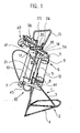
- the isobarometric sampling device consists of a tripod frame and grip handle having in the central part on the front a support for the sample collection container associated with a clamping mechanism of the container taking samples against the blanking plug, on the rear, two retaining collars for the neutral gas bottle and, in the upper part, a dispensing head having two inlet taps for gas and beer respectively, a pressurization valve on which is grafted a micrometric screw purge, an internal pressure control manometer and various connections; the apparatus also has, mounted between the dispensing head and the pressurizing valve, an element for adjusting the flow rate of the hydraulic discharge link controlled by the pressurizing valve. Connection members and a pressure reducer are also provided.
- the isobarometric sampling device firstly consists of a support frame 1, for example made of welded metal tubes consisting of a seat 2 in the form of a tripod 3 secured to a triangular base 4 , of an inclined central trunk 5 on which is attached in the rear part a support 6 for a bottle of inert gas under pressure such as 7.
- This support is formed for example of two parallel rings 8 and 9 forming a collar.
- the lower ring 8 comprises a cross member 10 on which the bottom of the bottle bears.
- the central trunk 5 carries, secured to its front face, two flat U-shaped irons such as 11 serving as fastening supports for a domed cover 12 preferably made of transparent plastic.
- An additional fork 13 provides protection against shocks.
- a block 14 is mounted integral with the upper end of the central trunk 5. In general parallelepipedic shape, it provides mechanically the connection between the frame 1 and a handle 15 integral with said block about halfway from its end for reasons of position of the center of gravity.
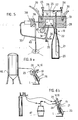
- This block forms the distribution head 16.
- This plug also has a concentric orifice outlet 22 serving as an exhaust passage for the injected liquid gas, in selective communication with the sink or with the atmosphere.
- the dispensing head 16 comprises, in the upper part, two inlet valves 23 and 24 respectively of nitrogen and beer. They regulate the flow of nitrogen or beer arriving in an internal common chamber 25 via a T-shaped bridge 26 with a common intake duct 27 opening into the sample-taking container by a separate extended duct 28 via the cannula 21.
- the gas and the liquid arrive laterally to the chamber by supply conduits 29 and 30 connected to a pressure regulator 31 receiving on the one hand the gas coming from the bottle and on the other hand the beer from the fermentation tank or barrel.
- the dispensing head has a lateral outlet 34 which is extended by a pressurizing tap 35 with two lateral outlets, the first in communication with the atmosphere by means of a purge 36 with a micrometric screw and the other connected by a conduit 37 at the control input of a regulating valve 38 with a membrane 39 regulating the flow rate of the evacuation circuit 40 and passing through the common interior chamber connecting the concentric orifice 22 to the sink through the valve.
- the regulation valve 38 more or less completely or completely blocks the evacuation circuit 40 connecting the orifice 22 to the sink according to the control pressure applied to its menbrane 39 transmitted by the conduit 37.
- the injection pipe 28 in connection with the intake pipe, communicates with the injection cannula 21.
- a clamping device 43 keeps the neck of the sample bottle 20 against the shutter plug 19.
- This device is constituted for example by a member 44 adjustable in approach or in distance terminated by a solid or cane-shaped end 45 in thrust contact with the slightly hollow bottom of the sampling bottle.
- the sample taking bottle 20 is mounted on its support by passing the cannula 21 through the neck, the neck is applied against the seal 18 of the shutter cap 19, the bottle is held and it is pressed strongly against the seal. tightness thanks to the clamping device 44, for example with a rod.
- the bottle is purged of its air by saturating it by injecting nitrogen under pressure. to do this, the nitrogen inlet valve 23 is opened. The nitrogen enters the bottle through the cannula 21 and exits through the concentric orifice 22 of the obturator plug.
- the discharge of nitrogen to the sink is enabled by the valve 38 which is pass-through for having left the pressurizing valve 35 open.
- the purging phase having ended, the filling phase is carried out.
- the communication 40 with the sink is cut by acting on the pressurizing valve 35.
- the membrane 39 of the valve 38 press-closes the connection with the sink. Nitrogen is admitted Until there prevails in the sampling bottle a pressure close to that existing in the fermentation tank or in the barrel which is known approximately by its theoretical value. this is displayed on the pressure gauge 42; it is adjusted downward using the purge 36 with a micrometric screw.
- the nitrogen supply is closed.
- the backpressure phase is complete, the filling itself is carried out.
- the tap 24 for admitting beer is opened. filling takes place slowly due to the nitrogen back pressure leaving only a small pressure difference.
- the invention makes it possible to take a sample from fermentation tank 46 but also from beer keg 47 as shown in FIGS. 6a and 6b.
Landscapes
- Life Sciences & Earth Sciences (AREA)
- Hydrology & Water Resources (AREA)
- Physics & Mathematics (AREA)
- Health & Medical Sciences (AREA)
- Chemical & Material Sciences (AREA)
- Analytical Chemistry (AREA)
- Biochemistry (AREA)
- General Health & Medical Sciences (AREA)
- General Physics & Mathematics (AREA)
- Immunology (AREA)
- Pathology (AREA)
- Sampling And Sample Adjustment (AREA)
- Measuring Or Testing Involving Enzymes Or Micro-Organisms (AREA)
- Apparatus Associated With Microorganisms And Enzymes (AREA)
Priority Applications (1)
| Application Number | Priority Date | Filing Date | Title |
|---|---|---|---|
| AT81440006T ATE13095T1 (de) | 1980-02-05 | 1981-02-05 | Selbstaendiges geraet zur isobarometrischen probenahme von kohlensaeurehaltigen getraenken. |
Applications Claiming Priority (2)
| Application Number | Priority Date | Filing Date | Title |
|---|---|---|---|
| FR8002743A FR2475223A1 (fr) | 1980-02-05 | 1980-02-05 | Appareil autonome de prelevement isobarometrique pour prise d'echantillons sur boissons gazeuses |
| FR8002743 | 1980-02-05 |
Publications (2)
| Publication Number | Publication Date |
|---|---|
| EP0033709A1 true EP0033709A1 (de) | 1981-08-12 |
| EP0033709B1 EP0033709B1 (de) | 1985-05-02 |
Family
ID=9238338
Family Applications (1)
| Application Number | Title | Priority Date | Filing Date |
|---|---|---|---|
| EP81440006A Expired EP0033709B1 (de) | 1980-02-05 | 1981-02-05 | Selbständiges Gerät zur isobarometrischen Probenahme von kohlensäurehaltigen Getränken |
Country Status (7)
| Country | Link |
|---|---|
| US (1) | US4380176A (de) |
| EP (1) | EP0033709B1 (de) |
| AT (1) | ATE13095T1 (de) |
| BE (1) | BE887378A (de) |
| DE (1) | DE3170238D1 (de) |
| FR (1) | FR2475223A1 (de) |
| IT (1) | IT1135268B (de) |
Cited By (3)
| Publication number | Priority date | Publication date | Assignee | Title |
|---|---|---|---|---|
| WO1992006363A1 (de) * | 1990-09-28 | 1992-04-16 | Otto Tuchenhagen Gmbh & Co. Kg | Verfahren und vorrichtung zur probengewinnung und probenhandhabung |
| EP0758086A3 (de) * | 1995-08-07 | 1998-05-20 | Centec Gesellschaft für Labor- und Prozessmesstechnik mbH | Verfahren und Vorrichtung zur Bestimmung produktspezifischer Qualitätsparameter einer Flüssigkeit |
| CN114610089A (zh) * | 2020-12-09 | 2022-06-10 | 深圳国技仪器有限公司 | 防结霜、防倒吸的内循环控温的吸收瓶存储仓 |
Families Citing this family (8)
| Publication number | Priority date | Publication date | Assignee | Title |
|---|---|---|---|---|
| US4651574A (en) * | 1985-04-05 | 1987-03-24 | Spencer R Wilson | Sample injection means |
| US5301560A (en) * | 1991-11-22 | 1994-04-12 | Texas Sampling, Inc. | Closed loop liquid sampler and sampling system |
| US5431067A (en) * | 1991-11-22 | 1995-07-11 | Texas Sampling, Inc. | Closed loop liquid sampler and sampling system |
| US5433120A (en) * | 1993-07-30 | 1995-07-18 | Texas Sampling, Inc. | Sampling system for septum closed container |
| US6854346B2 (en) * | 2001-09-17 | 2005-02-15 | Pgi International, Ltd. | Purging system for use with a gas sampling system |
| DE102005020985A1 (de) * | 2005-05-03 | 2006-11-09 | Forschungszentrum Jülich GmbH | Verfahren zur Probeentnahme sowie Probeentnahmevorrichtung |
| EP1764603A1 (de) * | 2005-09-20 | 2007-03-21 | AC Analytical Controls Holding B.V. | Probenahmesystem |
| EP3396351B1 (de) * | 2017-04-26 | 2022-11-09 | Furio Travagli | Vorrichtung und system zur direkten probenahme einer flüssigkeit eines tanks |
Citations (1)
| Publication number | Priority date | Publication date | Assignee | Title |
|---|---|---|---|---|
| FR2187115A5 (de) * | 1972-05-29 | 1974-01-11 | Aquitaine Petrole |
Family Cites Families (5)
| Publication number | Priority date | Publication date | Assignee | Title |
|---|---|---|---|---|
| US988657A (en) * | 1909-03-15 | 1911-04-04 | Richard Pfaff | Bottle-filling machine. |
| US3010583A (en) * | 1959-10-23 | 1961-11-28 | Millipore Filter Corp | Fluid sampling device |
| FR2379816A1 (fr) * | 1977-02-02 | 1978-09-01 | Tepral Grpt Interet Economique | Procede et installation pour le prelevement automatique d'echantillons de biere a analyser |
| FR2410824A1 (fr) * | 1977-12-02 | 1979-06-29 | Kronenbourg Brasseries | Installation et procede pour le prelevement d'echantillons de biere en vue de l'analyse des volatils |
| US4213342A (en) * | 1978-12-11 | 1980-07-22 | Gates Wendall C | Liquid sampler device |
-
1980
- 1980-02-05 FR FR8002743A patent/FR2475223A1/fr active Granted
-
1981
- 1981-02-03 IT IT19467/81A patent/IT1135268B/it active
- 1981-02-04 BE BE2/59000A patent/BE887378A/fr not_active IP Right Cessation
- 1981-02-04 US US06/231,511 patent/US4380176A/en not_active Expired - Fee Related
- 1981-02-05 DE DE8181440006T patent/DE3170238D1/de not_active Expired
- 1981-02-05 AT AT81440006T patent/ATE13095T1/de not_active IP Right Cessation
- 1981-02-05 EP EP81440006A patent/EP0033709B1/de not_active Expired
Patent Citations (1)
| Publication number | Priority date | Publication date | Assignee | Title |
|---|---|---|---|---|
| FR2187115A5 (de) * | 1972-05-29 | 1974-01-11 | Aquitaine Petrole |
Cited By (3)
| Publication number | Priority date | Publication date | Assignee | Title |
|---|---|---|---|---|
| WO1992006363A1 (de) * | 1990-09-28 | 1992-04-16 | Otto Tuchenhagen Gmbh & Co. Kg | Verfahren und vorrichtung zur probengewinnung und probenhandhabung |
| EP0758086A3 (de) * | 1995-08-07 | 1998-05-20 | Centec Gesellschaft für Labor- und Prozessmesstechnik mbH | Verfahren und Vorrichtung zur Bestimmung produktspezifischer Qualitätsparameter einer Flüssigkeit |
| CN114610089A (zh) * | 2020-12-09 | 2022-06-10 | 深圳国技仪器有限公司 | 防结霜、防倒吸的内循环控温的吸收瓶存储仓 |
Also Published As
| Publication number | Publication date |
|---|---|
| EP0033709B1 (de) | 1985-05-02 |
| FR2475223A1 (fr) | 1981-08-07 |
| IT1135268B (it) | 1986-08-20 |
| BE887378A (fr) | 1981-06-01 |
| ATE13095T1 (de) | 1985-05-15 |
| US4380176A (en) | 1983-04-19 |
| FR2475223B1 (de) | 1983-11-25 |
| DE3170238D1 (en) | 1985-06-05 |
| IT8119467A0 (it) | 1981-02-03 |
Similar Documents
| Publication | Publication Date | Title |
|---|---|---|
| EP0033709A1 (de) | Selbständiges Gerät zur isobarometrischen Probenahme von kohlensäurehaltigen Getränken | |
| RU2365538C2 (ru) | Разливочная машина с отдельным каналом возвратного газа | |
| CA1228797A (fr) | Appareil pour fournir un filet continu d'un liquide cryogenique, notamment d'azote liquide | |
| CA1288999C (fr) | Procede d'inertage d'emballages etanches et installation de mise en oeuvre | |
| EP0246979B1 (de) | Vorrichtung zur Erhaltung der Sterilität eines Kulturmediums in einem Behälter während der Probenentnahme | |
| EP0851026B1 (de) | Verfahren und Einrichtung zum Einbringen eines Inertgases in einen Getränkebehälter, insbesondere für Wein, und das Inertgas für diesen Zweck | |
| WO2003054441A1 (fr) | Dispositif de stockage et de melange de deux gaz | |
| CA2351107A1 (fr) | Dispositif de stockage et de melange de deux gaz | |
| US20190169014A1 (en) | Systems and methods for beverage preservation | |
| FR2533015A1 (fr) | Procede et dispositif d'injection d'un gaz liquefie de pressurisation dans des recipients | |
| US20200247654A1 (en) | Systems and methods for beverage preservation | |
| FR3121670A1 (fr) | Système de distribution d’un liquide depuis un réservoir de liquide et son procédé associé | |
| FR2622295A1 (fr) | Dispositif et procede pour determiner la teneur totale en soufre de combinaisons chimiques | |
| JPH06273309A (ja) | 樹脂膜のガス透過性測定装置 | |
| US711459A (en) | Apparatus for carbonating liquids in bottles or other receptacles. | |
| EP1332087B1 (de) | Verfahren und anlage zum verpacken einer flüssigkeit | |
| FR2566877A1 (fr) | Appareil destine au dosage precis des gaz liquefies et fluides divers | |
| EP0591045B1 (de) | Verfahren und Vorrichtung zum Füllen eines Behälters mit flüssiger Luft | |
| EP2597048A1 (de) | Zelle zum Messen der Durchlässigkeit von Korken | |
| BE701002A (de) | ||
| FR2921489A1 (fr) | Echantillonnage et stockage de produit en continu, sous pression constante et volume variable | |
| FR2688469A1 (fr) | Dispositif d'injection sequencee d'une dose de liquide cryogenique. | |
| EP3587287A1 (de) | Verfahren und vorrichtung zum herstellen einer kontrollierten atmosphäre in höhe der gasphase eines lagerbehälters eines produkts | |
| JP2022124983A (ja) | 液体移送装置および液体入り容器の製造方法 | |
| FR1410626A (fr) | Appareil pour prélever un échantillon sur un écoulement de lait |
Legal Events
| Date | Code | Title | Description |
|---|---|---|---|
| PUAI | Public reference made under article 153(3) epc to a published international application that has entered the european phase |
Free format text: ORIGINAL CODE: 0009012 |
|
| AK | Designated contracting states |
Designated state(s): AT DE GB NL SE |
|
| 17P | Request for examination filed |
Effective date: 19811222 |
|
| GRAA | (expected) grant |
Free format text: ORIGINAL CODE: 0009210 |
|
| AK | Designated contracting states |
Designated state(s): AT DE GB NL SE |
|
| REF | Corresponds to: |
Ref document number: 13095 Country of ref document: AT Date of ref document: 19850515 Kind code of ref document: T |
|
| REF | Corresponds to: |
Ref document number: 3170238 Country of ref document: DE Date of ref document: 19850605 |
|
| PG25 | Lapsed in a contracting state [announced via postgrant information from national office to epo] |
Ref country code: DE Effective date: 19851101 |
|
| PG25 | Lapsed in a contracting state [announced via postgrant information from national office to epo] |
Ref country code: AT Effective date: 19860205 |
|
| PG25 | Lapsed in a contracting state [announced via postgrant information from national office to epo] |
Ref country code: SE Effective date: 19860206 |
|
| PLBE | No opposition filed within time limit |
Free format text: ORIGINAL CODE: 0009261 |
|
| STAA | Information on the status of an ep patent application or granted ep patent |
Free format text: STATUS: NO OPPOSITION FILED WITHIN TIME LIMIT |
|
| 26N | No opposition filed | ||
| PG25 | Lapsed in a contracting state [announced via postgrant information from national office to epo] |
Ref country code: NL Effective date: 19860901 |
|
| GBPC | Gb: european patent ceased through non-payment of renewal fee | ||
| NLV4 | Nl: lapsed or anulled due to non-payment of the annual fee | ||
| PG25 | Lapsed in a contracting state [announced via postgrant information from national office to epo] |
Ref country code: GB Effective date: 19881118 |
|
| EUG | Se: european patent has lapsed |
Ref document number: 81440006.5 Effective date: 19861023 |