EP0033788A1 - Elektrisches Heizgerät - Google Patents
Elektrisches Heizgerät Download PDFInfo
- Publication number
- EP0033788A1 EP0033788A1 EP80200803A EP80200803A EP0033788A1 EP 0033788 A1 EP0033788 A1 EP 0033788A1 EP 80200803 A EP80200803 A EP 80200803A EP 80200803 A EP80200803 A EP 80200803A EP 0033788 A1 EP0033788 A1 EP 0033788A1
- Authority
- EP
- European Patent Office
- Prior art keywords
- support
- propeller
- flat
- elastic deformation
- slots
- Prior art date
- Legal status (The legal status is an assumption and is not a legal conclusion. Google has not performed a legal analysis and makes no representation as to the accuracy of the status listed.)
- Withdrawn
Links
- 238000005485 electric heating Methods 0.000 title claims abstract description 5
- 238000010438 heat treatment Methods 0.000 claims abstract description 10
- 230000005489 elastic deformation Effects 0.000 claims description 9
- 230000014759 maintenance of location Effects 0.000 claims 2
- 239000011810 insulating material Substances 0.000 claims 1
- 239000010445 mica Substances 0.000 description 5
- 229910052618 mica group Inorganic materials 0.000 description 5
- 238000012423 maintenance Methods 0.000 description 2
- 238000004519 manufacturing process Methods 0.000 description 2
- 238000005452 bending Methods 0.000 description 1
- 230000010339 dilation Effects 0.000 description 1
- 239000003292 glue Substances 0.000 description 1
- 238000009413 insulation Methods 0.000 description 1
- 230000002427 irreversible effect Effects 0.000 description 1
- 239000007787 solid Substances 0.000 description 1
Images

Classifications
-
- H—ELECTRICITY
- H05—ELECTRIC TECHNIQUES NOT OTHERWISE PROVIDED FOR
- H05B—ELECTRIC HEATING; ELECTRIC LIGHT SOURCES NOT OTHERWISE PROVIDED FOR; CIRCUIT ARRANGEMENTS FOR ELECTRIC LIGHT SOURCES, IN GENERAL
- H05B3/00—Ohmic-resistance heating
- H05B3/10—Heating elements characterised by the composition or nature of the materials or by the arrangement of the conductor
- H05B3/16—Heating elements characterised by the composition or nature of the materials or by the arrangement of the conductor the conductor being mounted on an insulating base
Definitions
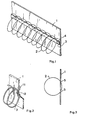
- the object of the present invention is a heating appliance equipped with a particularly simple heating element and of economical manufacture. It is characterized in that the heating element is composed of at least one wire wound in a helix whose end loops and several intermediate loops are secured to the support, for example by stapling. Preferably, the heating element is composed of at least two helically wound wires fixed on either side of the support. In the latter case, it is possible to assemble back to back two cartons of mica, each supporting a helically wound wire. Ultimately, each turn of the propeller can be maintained by the support or an element secured to the latter.
- a flat cardboard of mica serves as lateral support for a propeller 2 made of electric resistant wire with strongly spaced turns.
- tongue 3 in a heat-resistant insulation in this case a tongue of mica cardboard, of small width compared to the diameter of the propeller is introduced into the latter and secured to the support 1 by rivets 4 passing between two neighboring turns.
- the tongue 3 applies the propeller 2 laterally against the support.
- This fixing allows the wire to expand, but prevents it from vibrating if the wire is supplied with alternating current.
- rivets it is possible to use other heat-resistant fastening means, even glues.
- each loop When the wire is relatively stiff, it is not necessary to secure each loop with the support 1, it then suffices to fix the end loops and several intermediate loops to the support, for example as the case may be, each 3rd or 5th loop .
- This fixing can in particular be carried out by stapling the loops on the support 1 of mica cardboard.
- the staples 11 are provided with a tightening loop 12 conforming to the shape of the wire 2 of the propeller, in order to ensure that the wire is firmly held against the vibration forces which stress when it is traversed by nominal alternating current.
- the propeller 2 is threaded into pairs of holes 5.
- the spacing between two holes of a pair is substantially smaller than the diameter of the propeller. If the threading of the propeller wire in the holes imposes on it a different curvature than that which it presents not threaded, it is possible to pinch each turn firmly so as to once again ensure a solid fixing of the turns allowing their expansion and preventing vibration which in particular in the case of AC power supply could constitute a source of noise.
- the curvature of the propeller wire 2 in the execution according to FIG. 3 is determined by the thickness of the support 1 and the diameter of the holes 5.
- the particular advantage of the solution according to FIG. 1 is that it makes it possible to obtain rigid elements not only with respect to bending forces in the plane of the support 1 but also with respect to such forces perpendicular to the plane of the support. 1.
- the solution of figs.2 and 3 allows the manufacture of elements which can be bent around an axis, not shown, preferably on the opposite side of the support 1 relative to that where most of the the propeller 2.
- the propeller 2 can be held there by pinching or by means of a rod 8 threaded between the support 1 and the inner faces of the parts of the turns of the propeller 2 passing through the slots 6.
- a rod 8 threaded between the support 1 and the inner faces of the parts of the turns of the propeller 2 passing through the slots 6.
- Another possibility of causing the deformation of the turns necessary for the firm maintenance of the propeller 2 on the support 1 is to thread into the propeller 2 placed in slots 9 on the support 1 a rectangular flat insulating piece 10 of greater width the diameter of the propeller 2.
- the elastic deformation of the turns is chosen low enough so that at service temperature it does not turn into irreversible plastic deformation and strong enough so that at service temperature it has not disappeared because dilation of the propeller thread.
Landscapes
- Paper (AREA)
- Resistance Heating (AREA)
Applications Claiming Priority (2)
| Application Number | Priority Date | Filing Date | Title |
|---|---|---|---|
| LU82075A LU82075A1 (fr) | 1980-01-10 | 1980-01-10 | Element de chauffage electrique |
| LU82075 | 1980-01-10 |
Publications (1)
| Publication Number | Publication Date |
|---|---|
| EP0033788A1 true EP0033788A1 (de) | 1981-08-19 |
Family
ID=19729326
Family Applications (1)
| Application Number | Title | Priority Date | Filing Date |
|---|---|---|---|
| EP80200803A Withdrawn EP0033788A1 (de) | 1980-01-10 | 1980-08-27 | Elektrisches Heizgerät |
Country Status (2)
| Country | Link |
|---|---|
| EP (1) | EP0033788A1 (de) |
| LU (1) | LU82075A1 (de) |
Cited By (6)
| Publication number | Priority date | Publication date | Assignee | Title |
|---|---|---|---|---|
| FR2532808A1 (fr) * | 1982-09-08 | 1984-03-09 | Brasier Peter | Element chauffant electrique |
| US4789773A (en) * | 1985-07-31 | 1988-12-06 | E.G.O. Elektro-Gerate Blanc U. Fischer | Electrical radiant heater for heating heating surfaces |
| GB2335833A (en) * | 1998-03-25 | 1999-09-29 | Redring Electric Ltd | Support for coiled wire heating element |
| US6781099B2 (en) * | 2001-03-12 | 2004-08-24 | Karl-Heinz Krah Gmbh | Electrofusion socket forming system |
| WO2004086819A3 (en) * | 2003-03-21 | 2004-12-23 | Tutco Inc | Mica board electrical resistance wire heater , subassemblies components, and methods of assembly |
| CN100408958C (zh) * | 2003-12-25 | 2008-08-06 | 坂口电热株式会社 | 电炉 |
Citations (1)
| Publication number | Priority date | Publication date | Assignee | Title |
|---|---|---|---|---|
| GB650512A (en) * | 1948-07-24 | 1951-02-28 | Simplex Electric Co Ltd | Improvements in electrical heating apparatus |
-
1980
- 1980-01-10 LU LU82075A patent/LU82075A1/fr unknown
- 1980-08-27 EP EP80200803A patent/EP0033788A1/de not_active Withdrawn
Patent Citations (1)
| Publication number | Priority date | Publication date | Assignee | Title |
|---|---|---|---|---|
| GB650512A (en) * | 1948-07-24 | 1951-02-28 | Simplex Electric Co Ltd | Improvements in electrical heating apparatus |
Cited By (8)
| Publication number | Priority date | Publication date | Assignee | Title |
|---|---|---|---|---|
| FR2532808A1 (fr) * | 1982-09-08 | 1984-03-09 | Brasier Peter | Element chauffant electrique |
| US4789773A (en) * | 1985-07-31 | 1988-12-06 | E.G.O. Elektro-Gerate Blanc U. Fischer | Electrical radiant heater for heating heating surfaces |
| GB2335833A (en) * | 1998-03-25 | 1999-09-29 | Redring Electric Ltd | Support for coiled wire heating element |
| US6781099B2 (en) * | 2001-03-12 | 2004-08-24 | Karl-Heinz Krah Gmbh | Electrofusion socket forming system |
| US7144045B2 (en) | 2001-03-12 | 2006-12-05 | Karl-Heinz Krah Gmbh | Electrofusion socket forming system |
| US7767938B2 (en) | 2001-03-12 | 2010-08-03 | Karl-Heinz Krah Gmbh | Electrofusion socket forming system |
| WO2004086819A3 (en) * | 2003-03-21 | 2004-12-23 | Tutco Inc | Mica board electrical resistance wire heater , subassemblies components, and methods of assembly |
| CN100408958C (zh) * | 2003-12-25 | 2008-08-06 | 坂口电热株式会社 | 电炉 |
Also Published As
| Publication number | Publication date |
|---|---|
| LU82075A1 (fr) | 1980-04-23 |
Similar Documents
| Publication | Publication Date | Title |
|---|---|---|
| WO1980002775A1 (fr) | Dispositif de raccordement de conducteurs electriques isoles | |
| FR2517163A1 (fr) | Resistance electrique en tole raidie | |
| EP2662931B1 (de) | Anschlussschuh für isoliertes elektrisches Netzkabel, und Herstellungsverfahren dieses Anschlussschuhs | |
| LU82075A1 (fr) | Element de chauffage electrique | |
| WO1986005328A1 (fr) | Dispositif de connexion pour faisceau de fils electriques et procede de realisation | |
| WO1992014510A1 (fr) | Sonde vaginale | |
| FR2635908A1 (fr) | Resistance pour montage en surface et son procede de fabrication | |
| FR2472856A1 (fr) | Dispositif de contact electrique | |
| EP0635992B1 (de) | Heizelement | |
| EP0330630B1 (de) | Elektrischer Heizwiderstand für Warmluftgeneratoren | |
| FR2619954A3 (fr) | Bobine pour electro-aimants | |
| FR2530912A1 (fr) | Raccordement pour un corps de chauffe a rayonnement, avantageusement isole par des perles, en particulier pour un chauffage de four | |
| BE728077A (de) | ||
| FR2751474A1 (fr) | Dispositif de raccordement a conducteur monobrin | |
| EP1450440A1 (de) | Elektrische Verbindungseinrichtung insbesondere zwischen einem Schuttschalter und einem Differentialmodul | |
| FR2904489A1 (fr) | Capuchon de point neutre pour machine electrique tournante | |
| FR2508715A1 (fr) | Borne de contact electrique a serrage par vis | |
| FR2492153A1 (fr) | Transformateur de petite taille | |
| BE498277A (de) | ||
| BE649601A (de) | ||
| FR2948823A1 (fr) | Connecteur, grille de fausse coupure comprenant un tel connecteur et coffret de raccordement equipe d'une telle grille | |
| FR2848731A1 (fr) | Connecteur electrique et son procede de fabrication | |
| FR2493430A1 (fr) | Agrafe de retenue | |
| BE478059A (de) | ||
| CH683135A5 (fr) | Elément de connexion électrique et son utilisation. |
Legal Events
| Date | Code | Title | Description |
|---|---|---|---|
| PUAI | Public reference made under article 153(3) epc to a published international application that has entered the european phase |
Free format text: ORIGINAL CODE: 0009012 |
|
| AK | Designated contracting states |
Designated state(s): BE DE FR |
|
| RBV | Designated contracting states (corrected) |
Designated state(s): BE DE FR |
|
| STAA | Information on the status of an ep patent application or granted ep patent |
Free format text: STATUS: THE APPLICATION IS DEEMED TO BE WITHDRAWN |
|
| 18D | Application deemed to be withdrawn |
Effective date: 19820604 |
|
| RIN1 | Information on inventor provided before grant (corrected) |
Inventor name: DUBOIS, ANDRE |