EP0033886B2 - Dispositif pour ajuster les deux positions de serrage extrêmes qui limitent une course de serrage - Google Patents
Dispositif pour ajuster les deux positions de serrage extrêmes qui limitent une course de serrage Download PDFInfo
- Publication number
- EP0033886B2 EP0033886B2 EP81100547A EP81100547A EP0033886B2 EP 0033886 B2 EP0033886 B2 EP 0033886B2 EP 81100547 A EP81100547 A EP 81100547A EP 81100547 A EP81100547 A EP 81100547A EP 0033886 B2 EP0033886 B2 EP 0033886B2
- Authority
- EP
- European Patent Office
- Prior art keywords
- clamping
- sensors
- emitter
- jaws
- end positions
- Prior art date
- Legal status (The legal status is an assumption and is not a legal conclusion. Google has not performed a legal analysis and makes no representation as to the accuracy of the status listed.)
- Expired
Links
- 238000006073 displacement reaction Methods 0.000 claims description 20
- 230000000903 blocking effect Effects 0.000 claims description 4
- 230000003247 decreasing effect Effects 0.000 claims 2
- 230000006978 adaptation Effects 0.000 description 4
- 238000012544 monitoring process Methods 0.000 description 4
- 239000000243 solution Substances 0.000 description 3
- 238000010586 diagram Methods 0.000 description 2
- 238000012806 monitoring device Methods 0.000 description 2
- 230000006837 decompression Effects 0.000 description 1
- 230000000694 effects Effects 0.000 description 1
- 238000004519 manufacturing process Methods 0.000 description 1
- 238000004904 shortening Methods 0.000 description 1
Images



Classifications
-
- B—PERFORMING OPERATIONS; TRANSPORTING
- B23—MACHINE TOOLS; METAL-WORKING NOT OTHERWISE PROVIDED FOR
- B23Q—DETAILS, COMPONENTS, OR ACCESSORIES FOR MACHINE TOOLS, e.g. ARRANGEMENTS FOR COPYING OR CONTROLLING; MACHINE TOOLS IN GENERAL CHARACTERISED BY THE CONSTRUCTION OF PARTICULAR DETAILS OR COMPONENTS; COMBINATIONS OR ASSOCIATIONS OF METAL-WORKING MACHINES, NOT DIRECTED TO A PARTICULAR RESULT
- B23Q3/00—Devices holding, supporting, or positioning work or tools, of a kind normally removable from the machine
- B23Q3/16—Devices holding, supporting, or positioning work or tools, of a kind normally removable from the machine controlled in conjunction with the operation of the tool
-
- Y—GENERAL TAGGING OF NEW TECHNOLOGICAL DEVELOPMENTS; GENERAL TAGGING OF CROSS-SECTIONAL TECHNOLOGIES SPANNING OVER SEVERAL SECTIONS OF THE IPC; TECHNICAL SUBJECTS COVERED BY FORMER USPC CROSS-REFERENCE ART COLLECTIONS [XRACs] AND DIGESTS
- Y10—TECHNICAL SUBJECTS COVERED BY FORMER USPC
- Y10T—TECHNICAL SUBJECTS COVERED BY FORMER US CLASSIFICATION
- Y10T279/00—Chucks or sockets
- Y10T279/12—Chucks or sockets with fluid-pressure actuator
- Y10T279/1208—Chucks or sockets with fluid-pressure actuator with measuring, indicating or control means
-
- Y—GENERAL TAGGING OF NEW TECHNOLOGICAL DEVELOPMENTS; GENERAL TAGGING OF CROSS-SECTIONAL TECHNOLOGIES SPANNING OVER SEVERAL SECTIONS OF THE IPC; TECHNICAL SUBJECTS COVERED BY FORMER USPC CROSS-REFERENCE ART COLLECTIONS [XRACs] AND DIGESTS
- Y10—TECHNICAL SUBJECTS COVERED BY FORMER USPC
- Y10T—TECHNICAL SUBJECTS COVERED BY FORMER US CLASSIFICATION
- Y10T279/00—Chucks or sockets
- Y10T279/19—Radially reciprocating jaws
- Y10T279/1906—Radially reciprocating jaws with indicator
-
- Y—GENERAL TAGGING OF NEW TECHNOLOGICAL DEVELOPMENTS; GENERAL TAGGING OF CROSS-SECTIONAL TECHNOLOGIES SPANNING OVER SEVERAL SECTIONS OF THE IPC; TECHNICAL SUBJECTS COVERED BY FORMER USPC CROSS-REFERENCE ART COLLECTIONS [XRACs] AND DIGESTS
- Y10—TECHNICAL SUBJECTS COVERED BY FORMER USPC
- Y10T—TECHNICAL SUBJECTS COVERED BY FORMER US CLASSIFICATION
- Y10T279/00—Chucks or sockets
- Y10T279/20—Chucks or sockets with safety feature
Definitions
- the one final clamping position is reached when the clamping jaws approach the changing area when opening.
- the other final clamping position is reached when the clamping jaws close when they close where they can no longer be moved.
- both end tensioning positions must be far enough from the disengaged position or from the stop position that a tensioning stroke still remains, which also ensures secure tensioning in the end tensioning positions.
- the final clamping positions are now different for different large chucks, as are the clamping strokes.
- a device has already been developed (DE A 1752599) with which it can be monitored whether the clamping jaws are still within the clamping range defined by the final clamping positions. If it is determined that this is no longer the case, the machine cannot start.
- a support rod for a transmitter element is connected to the piston of the adjusting cylinder for the clamping jaws. With a clamping stroke adjustment, the carrier rod and with it the transmitter element moves.
- Two guides in the form of threaded bolts are arranged parallel to the support rod and can be rotated by knurled nuts. There is a sensor on each of the two threaded bolts. The sensors can be moved on the threaded bolts by turning the knurled nuts.
- the transmitter element measured in the longitudinal direction of the carrier rod, is shorter than the distance between the sensors.
- clamp travel end position monitoring for index Aohlspannylinders in which a support rod is also connected to the piston of the clamping cylinder for the clamping unit.
- This carrier rod serves to hold a ring acting as a donor element.
- An inductively responsive sensor to the ring is arranged along the displacement path of the carrier rod and the ring which it carries, which is set at the factory.
- a ring is assigned to each tensioning unit, which is exchanged with the tensioning unit.
- the individual rings differ in their width measured in the direction of displacement. The width of the rings is larger than the width of the sensor.
- the sensor signals that a final clamping position has been reached when the relevant ring is pushed out of the sensor's response range in one direction or the other. A reduction of the clamping stroke below the maximum clamping stroke given by the width of the ring and thus an adaptation of the clamping stroke to certain workpieces is not possible with this known device.
- the invention has for its object to provide a device for setting two a clamping stroke limiting end clamping positions of the adjustable jaws by a power drive of an interchangeable workpiece clamping unit of a machine tool and for determining the reaching of these end clamping positions, with which an adaptation of the clamping paths to the manufacturing workpieces is possible without a safety risk.
- a first embodiment of the invention is based on the device which has become known under the name “clamping travel end position monitoring for index hollow clamping cylinders”. It accordingly relates to a device for setting two end clamping positions limiting a clamping stroke of the clamping jaws adjustable by a power drive of an interchangeable workpiece clamping unit of a machine tool, and for determining the reaching of these final clamping positions, each with a transmitter element which is arranged on a carrier rod which can be displaced by the power drive, and with a sensor which can be displaced parallel to the support rod and which responds to the approach or contact of the transmitter element, with each clamping unit being assigned at least one specific part for fixing the end clamping positions, which can be exchanged with the clamping unit.
- the object is achieved in that a further sensor which can be displaced parallel to the carrier rod is provided, and that each clamping unit is assigned specific interchangeable stop elements for the displaceably arranged sensors which adjust the end clamping positions independently of the clamping stroke adjustment by changing the effective length of the sensor distance and thus a change compared to the basic distance size determining the maximum permissible clamping stroke in the sense of a clamping stroke reduction, allow the Transmitter element is longer than the distance of the sensors measured in the longitudinal direction of the support rod when they are in the stop position, and that the machine tool can only be put into operation when both sensors respond.
- a practical embodiment of the first embodiment can consist in that each sensor is arranged on a guide extending parallel to the carrier rod, and that interchangeable stop elements are provided for each guide.
- a further development can also consist in that, starting from the two stop elements of the two guides, adjustments of the assigned sensors in the opposite direction are possible, as a result of which the clamping stroke can be reduced.
- the guides can be formed by guide rods
- the stop elements can be formed by sleeves which are offset from the shoulder shoulders and are to be pushed onto the guide rod, on the thinner section of which the sensors are slidably arranged.
- the sleeves and / or guide rods be provided with locking means which prevent a sleeve from being pushed onto a guide rod which is not assigned to it.
- a second embodiment of the invention is also based on the device which has become known under the name “clamping travel end position monitoring for index hollow clamping cylinders”. Accordingly, this second embodiment relates to a device for setting two final clamping positions limiting a clamping stroke of the clamping jaws adjustable by a power drive of an interchangeable workpiece clamping unit of a machine tool, and for determining the reaching of these final clamping positions, with a transmitter element which is arranged on a carrier rod which can be displaced by the power drive , and with a sensor which is arranged along the displacement path of the sensor element and which reacts to the approach or contact of the sensor element, the sensor element being exchangeable and each sensor unit being assigned a sensor element with a basic length which determines the final clamping positions.
- a further sensor that reacts to the approach or contact of the transmitter element is arranged along the displacement path of the transmitter element, that the transmitter element is longer than the distance of the sensors measured in the longitudinal direction of the carrier rod, that the transmitter element an adjustment of the end clamping positions independent of the clamping stroke adjustment by changing the effective length of the encoder element and thus a change compared to the basic distance size determining the maximum permissible clamping stroke in the sense of a clamping stroke reduction, and that the machine tool can only be put into operation when both sensors respond.
- An expedient embodiment of this second embodiment can consist in the fact that the transmitter element consists of two telescopically interlocking parts arranged one behind the other in the longitudinal direction of the carrier rod, which parts can be adjusted from one another in the sense of shortening the transmitter element in order to reduce the stroke, if necessary.
- a third embodiment of the invention is based on the device known under the term “clamping travel end position monitoring for index hollow clamping cylinders” for setting two final clamping positions that limit a clamping stroke of the clamping jaws of a replaceable workpiece clamping unit of a machine tool that can be adjusted by a power drive, and for determining whether they have been reached End clamping positions, each with a transmitter element which is arranged on a support rod that can be displaced by the power drive and with a sensor arranged along the displacement path of the transmitter element, with each clamping unit being assigned at least one specific part for determining the end clamping positions, which can be exchanged with the clamping unit.
- the object is achieved by providing a further sensor arranged along the displacement path of the transmitter element, and by assigning each clamping unit as a specific part an interchangeable sensor arrangement with a specific sensor distance, which adjusts the end clamping positions independently of the clamping stroke adjustment Changing the effective length of the sensor distance and thus a change compared to the basic distance size determining the maximum permissible clamping stroke in the sense of a clamping stroke reduction allows the transmitter element to be shorter than the distance of the sensors measured in the longitudinal direction of the carrier rod, and that the power drive can only be put into operation, if neither sensor responds.
- An expedient embodiment of the third embodiment can consist in that these sensors can be adjusted towards one another from a stop position.
- the three embodiments described above have in common that at least one specific part of the transmitter and / or sensor arrangement is replaced with the tensioning unit.
- the fourth embodiment is based on the known device (DE-A 1 752 599) described first. It accordingly relates to a device for setting two final clamping positions limiting a clamping stroke of the clamping jaws of an interchangeable workpiece clamping unit of a machine tool, which clamping jaws can be adjusted by a power drive, and for determining whether these final clamping positions have been reached, consisting of an encoder and a sensor arrangement, which react to approach or contact and whose distance can be changed with the jaw adjustment.
- the task on which the invention is based is achieved according to this fourth embodiment in that at least one specific part of the transmitter and / or sensor arrangement is assigned to each clamping unit for determining the final clamping positions, which can be automatically put into operation with the clamping unit.
- each clamping unit can be provided with a code transmitter, the code of which can be read out by a code reader, which in turn controls a selection circuit for the sensors.
- the sensors can be arranged concentrically around the support rod.
- the carrier rod can be arranged axially displaceably in a cylindrical drum. Holders for the sensors can then be attached to the drum.
- a fifth embodiment of the invention is also based on the known device (DE-A 1 752 599) described first. It accordingly relates to a device for setting two final clamping positions limiting a clamping stroke of the clamping jaws adjustable by a power drive of an exchangeable workpiece clamping unit of a machine tool, and for determining whether these relaxation positions have been reached.
- the object of the invention is achieved by a voltage position actual value transmitter, which is also adjusted in the jaw adjustment, by a voltage position nominal value transmitter for the widest and the narrowest clamping position, and by a comparator connected to the actual value transmitter and the nominal value transmitter, which, if a match is found a blocking signal for the machine tool is generated from the setpoint and actual value.
- a voltage position actual value transmitter which is also adjusted in the jaw adjustment
- a voltage position nominal value transmitter for the widest and the narrowest clamping position for the widest and the narrowest clamping position
- a comparator connected to the actual value transmitter and the nominal value transmitter, which, if a match is found a blocking signal for the machine tool is generated from the setpoint and actual value.
- each clamping unit is provided with a code transmitter, the code of which can be read out by a code reader, that a target code is output by a program control for the machine tool, and that a further comparator is provided that matches that of the code reader compares the read code with the target code and generates a locking signal for the machine tool if there is a deviation.
- the actual clamping position encoder can be a linear measuring element coupled to the piston-cylinder arrangement, which works as a contactless encoder-sensor arrangement.
- the actual clamping position value is well suited to be evaluated as a test value for the workpiece.
- Fig. 1 shows the chuck 1 of a lathe.
- a clamping cylinder 2 which is connected to the chuck 1 via a rod 3, serves to adjust the jaws of the chuck.
- a cylindrical transmitter element 5 is seated on a rod 4 which extends to the other side.
- Two sensors 6 and 7 are arranged in the displacement area of the transmitter element 5. The two sensors are slidably arranged on a rod 10. The displacement range of the two sensors 6 and 7 is limited by stops 8 and 9. The two sensors 6 and 7 can be moved away from one another from the stop position.
- the tensioning cylinder 2 is supplied with a pressure medium coming from a pressure medium pump 14 via two valves 12 and 13 connected in series.
- a pressure medium sump is designated 15.
- the valve 12 is normally in the closed position.
- An AND circuit 11 generates an opening signal for the valve 12 only when both sensors 6 and 7 respond to the transmitter 5.
- the clamping cylinder 2 can be displaced.
- the direction of displacement is determined by an adjustment signal emitted by the control 16 for the chuck power drive.
- the controller 16 reports back that the prescribed stroke has been exceeded by the AND circuit 11. If the power drive is to be put into operation again after the valve 12 has been switched over to the closed position, the controller 16 gives the valve 12 an opening pulse.
- the piston of the clamping cylinder 2 When the jaws of the chuck 1 are in their closing end clamping position, the piston of the clamping cylinder 2 has a rightmost position. In this closing end clamping position, the sensor 6 is responding to the left end of the transmitter element 5. The sensor 7 is located above the central area of the transmitter element 5 and also responds. Now the piston and the donor element 5 are shifted to the left. In the opening end clamping position, the sensor 7 just responds to the right end of the transmitter element 5.
- the output signal of the AND circuit 11 is also fed to one input of a further AND circuit 17, the other input of which is supplied with the switch-on signal for the spindle drive.
- the output of the further AND circuit 17 leads to the spindle drive. This ensures that the spindle drive can only be switched on when the clamping jaws are within the prescribed stroke range, i.e. that is, if the transmitter element 5 does not move out of the response range of one of the sensors 6, 7.
- the clamping stroke can be reduced by moving the sensor 7 on the rod 10 to the right.
- the device can be adapted to this newly exchanged chuck in that the stops 8 and 9 are exchanged for other stops. How this can be done in practice is explained in connection with FIGS. 5 to 7.
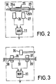
- the transmitter element 25 here consists of two sleeves 25a, 25b which are arranged displaceably on the rod 4 and which telescopically interlock.
- the end positions of the two sleeves 25a, 25b are determined by stops 28 and 29.
- the stops 28, 29 can be changed.
- a short transmitter element 35 is fixedly arranged on the rod 4.
- sensors 36, 37 are arranged displaceably on the rod 10.
- the displacement ranges of the sensors 36, 37 are limited by stops 38, 39.
- the stops 38, 39 allow the sensors 36, 37 to be moved relative to one another.
- the valve 12 is opened when neither of the two sensors 36, 37 responds.
- the two sensors 36, 37 are connected to a NOR circuit 31, which controls the valve 12.
- the sensor 37 determines the closing final clamping position.
- the sensor 36 determines the final opening tension position.
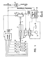
- a short transmitter element 55 is fixedly arranged on the rod 4.
- a large number of fixed sensors 56-64 are located in the displacement area of the transmitter element 55.
- the sensors are connected to a selection circuit 156.
- the code reader 65 then gives the selection circuit a signal corresponding to the code read.
- the selection circuit 54 selects two of the sensors 56-64 in accordance with the read signal and switches the signals supplied by the sensors le to the NOR circuit 31. As described, this controls the valve 12. A change is not to be made here. Instead, the sensors assigned to the respective chuck 1 are automatically selected and put into operation.
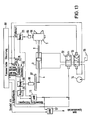
- a practical implementation is described below in connection with FIGS. 10 to 12.
- the other circuit parts correspond to those in FIG. 1.
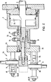
- the power clamping cylinder 2 is flanged to the wall 74 of a spindle housing. Its piston 75 is connected on the one hand to the chuck via a pull rod 3 and on the other hand projects into a distributor housing 72 through which the pressure medium is conducted to the cylinder.
- Such pressure medium distributors are known and are therefore only indicated schematically. They each have a pressure medium connection 76, 77 for tensioning and decompression and, if necessary, a leakage oil line 78.
- a rod 4 is screwed into the extension of the piston 75 projecting into the distributor housing 72 and protrudes from the distributor housing 72 and on which the transmitter element 5 is fixed immovably.
- a holding plate 79 is attached to the pressure medium distributor 72 and carries two pairs of guide columns 80, 81 and 82, 83.
- a stepped sleeve 84, 85 which in turn carries a sensor receptacle 86, 87, is pushed onto each of the guide columns 80, 82.
- the sensor receptacles 86, 87 are slotted in two places, so that they can be clamped on the thinner sections of the sleeves and in them the sensors.
- the shoulders of the sleeves form stops 8 and 9 for the sensor receptacles 86, 87.
- FIG. 6 it can also be seen that the sensor receptacles 86, 87 are supported against rotation on the respective second guide column 81, 83.
- the sensors are arranged perpendicular to the guide columns.
- a test piece is clamped in the chuck.
- the sensor 6 is now displaced by means of its holder 86 in such a way that it just just responds to the transmitter element 5.
- the sensor 7 is set so that the chuck offers a sufficient opening for inserting the workpieces. As a rule, the full stroke up to the end position will be used for opening. However, a shorter stroke can be selected with the sensor 7.
- the sensor 7 then closes the pressure medium supply line and at the same time prevents the machine spindle from starting. If both sensors 6 and 7 respond, the voltage is correct and the spindle can start up. As soon as one of the two sensors 6, 7 is de-energized, the drive of the spindle is blocked.
- the sensor receptacles 86, 87 can now only be moved up to the shoulders 8, 9 of the sleeves 84, 85.
- the shoulders limit the permissible clamping range of the associated chuck. Moving the sensor receptacles 86, 87 away from the shoulders of the sleeves reduces the clamping stroke and can therefore not impair safety.
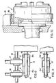
- FIGS. 9 and 9 corresponds to the schematic illustration in FIG. All that needs to be added is that the telescopically interlocking sleeves 25a, 25b are releasably attached to the rod 4 by means of grub screws 41, 42.
- the two stops 28 and 29 are formed on the one hand by a nut and on the other hand by a snap ring.
- the exchanged sensor element in FIG. 9 consists of two stepped sleeves 25a 'and 25b ' .
- the narrowness of the sensor element 25 ′ in FIG. 9, which is effective for the sensor effect is less than that of the sensor element 25 in FIG. 8.
- FIGS. 10 to 12 corresponds to the schematic representation in FIG. 4. It can be seen that the sensors 56 to 64 are fastened on sensor holders 67. The sensor holders 67 are in turn attached to a drum 68 and concentrically surround the drum axis. The rod 4, which carries the transmitter element 55, runs along the drum axis.
- a lining 1 is shown coarsened in FIG.
- the code transmitter 66 and the code reader 65 are clearly visible here.
- the code transmitter 66 is designed as a ring which surrounds the chuck 1 concentrically.
- the rod 4 is connected to a position sensor 97, which is sensed by a sensor 96.
- a numerical controller 90 sends the two stroke limitation values for the chuck to a setpoint selection circuit 92. Furthermore, the numerical control gives the signals for controlling the direction of displacement of the power drive to the valve 13. These signals are fed to the setpoint selection circuit 92. Depending on whether the chuck is to be opened or closed, this only forwards the value for the maximum or the value for the minimum clamping position to a comparator 93, to which the actual value position of the chuck read out by sensor 96 is also fed. If the comparator 93 determines a match, it outputs a signal.
- the numerical control 90 also outputs to a further comparator 91 a feed type target signal which is compared with the feed type actual signal read out by the code reader 66. If there is a match, the further comparator 91 outputs a signal to one input of the AND circuit 11, the other input of which is supplied with the signal generated by the negation circuit 94.
- the AND circuit 11 thus generates here for that Valve 12 an opening signal when the chuck in the machine corresponds to that specified by the numerical control 90 and when the jaws are within the prescribed stroke range.
- the other circuit parts are as in FIG. 1.
Landscapes
- Engineering & Computer Science (AREA)
- Mechanical Engineering (AREA)
- Gripping On Spindles (AREA)
- Jigs For Machine Tools (AREA)
Claims (18)
Priority Applications (1)
| Application Number | Priority Date | Filing Date | Title |
|---|---|---|---|
| AT81100547T ATE4786T1 (de) | 1980-02-11 | 1981-01-26 | Vorrichtung zur einstellung von zwei einen spannhub begrenzenden endspannpositionen. |
Applications Claiming Priority (2)
| Application Number | Priority Date | Filing Date | Title |
|---|---|---|---|
| DE3004988A DE3004988C2 (de) | 1980-02-11 | 1980-02-11 | Vorrichtung zur Einstellung von zwei einen Spannhub begrenzenden Endspannpositionen |
| DE3004988 | 1980-02-11 |
Publications (3)
| Publication Number | Publication Date |
|---|---|
| EP0033886A1 EP0033886A1 (fr) | 1981-08-19 |
| EP0033886B1 EP0033886B1 (fr) | 1983-09-28 |
| EP0033886B2 true EP0033886B2 (fr) | 1988-05-11 |
Family
ID=6094288
Family Applications (1)
| Application Number | Title | Priority Date | Filing Date |
|---|---|---|---|
| EP81100547A Expired EP0033886B2 (fr) | 1980-02-11 | 1981-01-26 | Dispositif pour ajuster les deux positions de serrage extrêmes qui limitent une course de serrage |
Country Status (4)
| Country | Link |
|---|---|
| US (1) | US4443021A (fr) |
| EP (1) | EP0033886B2 (fr) |
| AT (1) | ATE4786T1 (fr) |
| DE (1) | DE3004988C2 (fr) |
Families Citing this family (20)
| Publication number | Priority date | Publication date | Assignee | Title |
|---|---|---|---|---|
| DE3105872C2 (de) * | 1981-02-18 | 1984-12-06 | Paul Forkardt GmbH & Co KG, 4000 Düsseldorf | Einrichtung zur Bestimmung des Arbeitshubes des Kolbens eines doppeltwirkenden Spannzylinders zur Betätigung von Spanneinrichtungen an Werkzeugmaschinen |
| DE3228749C2 (de) * | 1982-07-31 | 1986-10-16 | Paul Forkardt GmbH & Co KG, 4000 Düsseldorf | Einrichtung zur Bestimmung des Arbeitsbereiches eines doppeltwirkenden Spannzylinders zur Betätigung von Spanneinrichtungen an Werkzeugmaschinen, insbesondere von auswechselbaren Spannfuttern an Drehmaschinen |
| ATE30390T1 (de) * | 1982-11-10 | 1987-11-15 | Roehm Guenter H | Kraftbetaetigtes spannfutter. |
| EP0213218B1 (fr) * | 1985-08-27 | 1988-10-05 | Paul Forkardt GmbH & Co. KG | Procédé d'ajustage de la force de serrage d'un mandrin rotatif de machines-outils |
| GB8521514D0 (en) * | 1985-08-29 | 1985-10-02 | Pratt Int Ltd Burnerd | Chucks |
| US5257199A (en) * | 1985-09-11 | 1993-10-26 | Omron Tateisi Electronics | Apparatus for identifying tools and for managing tool data |
| DE3719102A1 (de) * | 1987-06-06 | 1988-12-15 | Smw Spanneinrichtungen | Umlaufender spannzylinder fuer kraftspannfutter |
| JP3677416B2 (ja) * | 1998-10-23 | 2005-08-03 | 株式会社森精機ハイテック | 電動チャックの制御方法および装置 |
| FR2784917B1 (fr) * | 1998-10-23 | 2000-12-29 | Gamet Prec | Procede de commande du serrage et du desserrage d'un mandrin a commande hydraulique |
| JP4122490B2 (ja) * | 1999-10-04 | 2008-07-23 | Smc株式会社 | 位置検出機構付き複合型エアチャック |
| DE20012080U1 (de) * | 2000-07-12 | 2000-12-07 | Röhm GmbH, 89567 Sontheim | Komplett-Spannsystem an einer Drehmaschine |
| CN101653938B (zh) * | 2008-08-22 | 2012-12-12 | 比亚迪股份有限公司 | 一种可检测机械爪、可检测机械手及其检测方法 |
| KR101336538B1 (ko) | 2011-12-23 | 2013-12-03 | 현대위아 주식회사 | 공작물의 클램핑 및 언클램핑 디텍팅장치 |
| JP6191292B2 (ja) * | 2013-07-10 | 2017-09-06 | Smc株式会社 | 工作機械用チャック装置及び工作機械のチャック方法 |
| JP6700050B2 (ja) | 2016-01-26 | 2020-05-27 | 中村留精密工業株式会社 | チャックの開閉制御装置 |
| JP6960659B2 (ja) * | 2017-06-27 | 2021-11-05 | 中村留精密工業株式会社 | 工作機械のローディングシステム |
| JP7101987B2 (ja) * | 2018-10-18 | 2022-07-19 | 中村留精密工業株式会社 | 計測機能付主軸を備えた工作機械 |
| US11123832B2 (en) * | 2018-10-18 | 2021-09-21 | Nakamura-Tome Precision Industry Co., Ltd. | Workpiece holding device and loading apparatus that uses the workpiece holding device |
| JP7448739B2 (ja) | 2019-05-27 | 2024-03-13 | Smc株式会社 | チャック装置の駆動システム及びその制御方法 |
| CH716376B1 (de) * | 2020-07-08 | 2020-12-30 | Reishauer Ag | Umrüstbare Greifvorrichtung. |
Family Cites Families (5)
| Publication number | Priority date | Publication date | Assignee | Title |
|---|---|---|---|---|
| DE1214307B (de) * | 1964-08-06 | 1966-04-14 | Siemens Ag | Regeleinrichtung zur Positionierung von Arbeitsmaschinen |
| DE1752593B2 (de) * | 1968-06-20 | 1976-11-18 | Siemens AG, 1000 Berlin und 8000 München | Einrichtung zum drehzahlunabhaengigen stillsetzen von pressen |
| DE1752599A1 (de) * | 1968-06-20 | 1971-09-30 | Berg & Co Gmbh | Sicherheits-Abschaltvorrichtung fuer Spannaggregate an Werkzeugmaschinen |
| DE2711908A1 (de) * | 1977-03-18 | 1978-09-28 | Nagel Masch Werkzeug | Einrichtung zur hubumsteuerung an honmaschinen |
| DD142854A1 (de) * | 1979-04-16 | 1980-07-16 | Lothar Schubert | Sicherheitseinrichtung fuer kraftbetaetigte spannfutter |
-
1980
- 1980-02-11 DE DE3004988A patent/DE3004988C2/de not_active Expired
-
1981
- 1981-01-26 AT AT81100547T patent/ATE4786T1/de not_active IP Right Cessation
- 1981-01-26 EP EP81100547A patent/EP0033886B2/fr not_active Expired
- 1981-02-06 US US06/232,305 patent/US4443021A/en not_active Expired - Fee Related
Also Published As
| Publication number | Publication date |
|---|---|
| DE3004988C2 (de) | 1987-10-01 |
| DE3004988A1 (de) | 1981-08-20 |
| EP0033886B1 (fr) | 1983-09-28 |
| EP0033886A1 (fr) | 1981-08-19 |
| ATE4786T1 (de) | 1983-10-15 |
| US4443021A (en) | 1984-04-17 |
Similar Documents
| Publication | Publication Date | Title |
|---|---|---|
| EP0033886B1 (fr) | Dispositif pour ajuster les deux positions de serrage extrêmes qui limitent une course de serrage | |
| DE3108891C2 (de) | Elektrisches Bolzenschweißgerät Kennwort: Codierung | |
| DE3039467A1 (de) | Honmaschine zum bearbeiten von werkstueckbohrungen, insbesondere von sacklochbohrungen und verfahren zum betrieb der honmaschine | |
| DE102010037545A1 (de) | Pneumatisches Koppelmodul, insbesondere für ein Nullpunktspannsystem für eine Werkzeugmaschine | |
| EP0470536A1 (fr) | Outil de mesure de honage | |
| DE1402917B2 (de) | Vorrichtung zum ueberwachen der werkzeugabnutzung an einer umlaufenden werkzeugspindel, insbesondere bohrspindel | |
| DE1270932B (de) | Vorschubsteuervorrichtung, insbesondere an einer Gewindebohrmaschine | |
| DE102015005634A1 (de) | Vorrichtung zur Minimalmengenschmierung | |
| DE3208389A1 (de) | Numerische steuerung fuer bearbeitungsmaschinen | |
| DE2208708B2 (de) | Adaptive Regelungsvorrichtung für Verzahnmaschinen, insbesondere Stirnradwälzfräsmaschinen | |
| DE3133246C2 (de) | Elektrische Steuerungsvorrichtung für die anschlaglose Wegbegrenzung an Werkzeugmaschinen, insbesondere an Honmaschinen | |
| DE3532592C2 (fr) | ||
| EP0302187B1 (fr) | Dispositif de serrage sur tours avec mandrin | |
| DE2711862C2 (fr) | ||
| DE3013378C2 (de) | Einrichtung zur adaptiven Regelung von Bearbeitungsprozessen an Schleifmaschinen, insbesondere an Rundschleifmaschinen | |
| DE2423692B2 (de) | Meßsteuerungsvorrichtung zum automatischen Nachstellen des Werkzeuges einer spanenden Werkzeugmaschine | |
| DE2501196A1 (de) | Drehbares backenfutter mit vorratsanzeiger | |
| EP0296594A2 (fr) | Méthode et dispositif d'alignement réciproque de galets de formage | |
| DE2329420C3 (de) | Hydraulische Kopiersteuervorrichtung | |
| DE876635C (de) | Vorrichtung zum Verriegeln eines Revolverkopfes | |
| DE3050806C2 (de) | Vorrichtung zur Einstellung von zwei einen Spannhub begrenzenden Endpositionen der durch einen Kraftantrieb verstellbaren Spannbacken eines auswechselbaren Spannfutters einer Werkzeugmaschine | |
| DE4318446A1 (de) | Blasluftbeaufschlagte Wendestange zum Umlenken einer bedruckten Warenbahn | |
| DE3039659C2 (de) | Werkzeugeinsatz für eine Bohrstange od. dgl. | |
| DE102015224348A1 (de) | Vorrichtung und Verfahren zum kraftgesteuerten Klemmen von zu bearbeitenden Bauteilen | |
| DE3505275C1 (de) | Vorrichtung zum Regeln eines Stellgliedes |
Legal Events
| Date | Code | Title | Description |
|---|---|---|---|
| PUAI | Public reference made under article 153(3) epc to a published international application that has entered the european phase |
Free format text: ORIGINAL CODE: 0009012 |
|
| AK | Designated contracting states |
Designated state(s): AT CH FR GB IT SE |
|
| 17P | Request for examination filed |
Effective date: 19810727 |
|
| ITF | It: translation for a ep patent filed | ||
| GRAA | (expected) grant |
Free format text: ORIGINAL CODE: 0009210 |
|
| AK | Designated contracting states |
Designated state(s): AT CH FR GB IT LI SE |
|
| REF | Corresponds to: |
Ref document number: 4786 Country of ref document: AT Date of ref document: 19831015 Kind code of ref document: T |
|
| ET | Fr: translation filed | ||
| PLBI | Opposition filed |
Free format text: ORIGINAL CODE: 0009260 |
|
| 26 | Opposition filed |
Opponent name: INDEX-WERKE KG HAHN & TESSKY Effective date: 19840626 |
|
| PUAH | Patent maintained in amended form |
Free format text: ORIGINAL CODE: 0009272 |
|
| STAA | Information on the status of an ep patent application or granted ep patent |
Free format text: STATUS: PATENT MAINTAINED AS AMENDED |
|
| 27A | Patent maintained in amended form |
Effective date: 19880511 |
|
| AK | Designated contracting states |
Kind code of ref document: B2 Designated state(s): AT CH FR GB IT SE |
|
| ITF | It: translation for a ep patent filed | ||
| ET3 | Fr: translation filed ** decision concerning opposition | ||
| PGFP | Annual fee paid to national office [announced via postgrant information from national office to epo] |
Ref country code: SE Payment date: 19900104 Year of fee payment: 10 |
|
| PG25 | Lapsed in a contracting state [announced via postgrant information from national office to epo] |
Ref country code: SE Effective date: 19910127 |
|
| ITTA | It: last paid annual fee | ||
| PGFP | Annual fee paid to national office [announced via postgrant information from national office to epo] |
Ref country code: AT Payment date: 19950120 Year of fee payment: 15 |
|
| EUG | Se: european patent has lapsed |
Ref document number: 81100547.9 Effective date: 19910910 |
|
| PG25 | Lapsed in a contracting state [announced via postgrant information from national office to epo] |
Ref country code: AT Effective date: 19960126 |
|
| REG | Reference to a national code |
Ref country code: CH Ref legal event code: PUE Owner name: GILDEMEISTER AKTIENGESELLSCHAFT TRANSFER- ROEHM-GE |
|
| REG | Reference to a national code |
Ref country code: GB Ref legal event code: 732E |
|
| REG | Reference to a national code |
Ref country code: FR Ref legal event code: TP |
|
| PGFP | Annual fee paid to national office [announced via postgrant information from national office to epo] |
Ref country code: GB Payment date: 19991029 Year of fee payment: 20 |
|
| PGFP | Annual fee paid to national office [announced via postgrant information from national office to epo] |
Ref country code: FR Payment date: 19991130 Year of fee payment: 20 |
|
| PGFP | Annual fee paid to national office [announced via postgrant information from national office to epo] |
Ref country code: CH Payment date: 19991224 Year of fee payment: 20 |
|
| PG25 | Lapsed in a contracting state [announced via postgrant information from national office to epo] |
Ref country code: LI Free format text: LAPSE BECAUSE OF EXPIRATION OF PROTECTION Effective date: 20010125 Ref country code: CH Free format text: LAPSE BECAUSE OF EXPIRATION OF PROTECTION Effective date: 20010125 Ref country code: GB Free format text: LAPSE BECAUSE OF EXPIRATION OF PROTECTION Effective date: 20010125 |
|
| REG | Reference to a national code |
Ref country code: GB Ref legal event code: PE20 Effective date: 20010125 |
|
| REG | Reference to a national code |
Ref country code: CH Ref legal event code: PL |