EP0033991B1 - Plattenspieler - Google Patents
Plattenspieler Download PDFInfo
- Publication number
- EP0033991B1 EP0033991B1 EP81200100A EP81200100A EP0033991B1 EP 0033991 B1 EP0033991 B1 EP 0033991B1 EP 81200100 A EP81200100 A EP 81200100A EP 81200100 A EP81200100 A EP 81200100A EP 0033991 B1 EP0033991 B1 EP 0033991B1
- Authority
- EP
- European Patent Office
- Prior art keywords
- pick
- arm
- control element
- path
- coupling portion
- Prior art date
- Legal status (The legal status is an assumption and is not a legal conclusion. Google has not performed a legal analysis and makes no representation as to the accuracy of the status listed.)
- Expired
Links
- 238000010168 coupling process Methods 0.000 claims description 54
- 238000005859 coupling reaction Methods 0.000 claims description 54
- 230000008878 coupling Effects 0.000 claims description 53
- 238000006073 displacement reaction Methods 0.000 claims description 11
- 238000001746 injection moulding Methods 0.000 description 3
- 238000010276 construction Methods 0.000 description 2
- 241001422033 Thestylus Species 0.000 description 1
- 230000005540 biological transmission Effects 0.000 description 1
Images


Classifications
-
- G—PHYSICS
- G11—INFORMATION STORAGE
- G11B—INFORMATION STORAGE BASED ON RELATIVE MOVEMENT BETWEEN RECORD CARRIER AND TRANSDUCER
- G11B3/00—Recording by mechanical cutting, deforming or pressing, e.g. of grooves or pits; Reproducing by mechanical sensing; Record carriers therefor
- G11B3/02—Arrangements of heads
- G11B3/08—Raising, lowering, traversing otherwise than for transducing, arresting, or holding-up heads against record carriers
- G11B3/085—Raising, lowering, traversing otherwise than for transducing, arresting, or holding-up heads against record carriers using automatic means
- G11B3/08535—Driving the head
- G11B3/08538—Driving the head the head being driven by the same means as the record can
- G11B3/08541—Driving the head the head being driven by the same means as the record can for pivoting pick-up arms
- G11B3/08545—Driving the head the head being driven by the same means as the record can for pivoting pick-up arms driven by cams
Definitions
- the control element After the pick-up arm has been returned to an end position through a movement in the first direction, the control element, after being locked, and thus the pick-up arm are slightly pivoted back under the influence of the control spring. Thus the pick-up arm is moved to the rest position with a detour, which results in loss of time and an unsteady movement of the pick-up arm. Further as a result of inaccurate adjustment or wear it is possible that the control element will not be locked correctly after tensioning of the control spring, so that the pick-up arm is again moved in the second direction from the rest position towards the turntable, which is undesirable.
- the frame carries guide means for the control element, which guide means, when the rod is moved in the first and second directions during control of the pick-up arm in the second direction of movement, cause the coupling portion of the control element to follow first and second paths respectively, which paths are substantially concentric with the axis of the pick-up arm spindle, the first path being situated at a greater radial distance from said axis than the second path and the coupling portion of the control element being engageable with the coupling portion of the pick-up arm lever in the second path only.
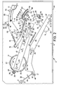
- the record player shown in Figure 1 comprises a frame 1 on which a turntable 2 is mounted for rotation about an axis 3.
- a pick-up arm spindle 4 is journalled in the frame 1, which spindle extends through a deck plate 5 of the frame 1 and is rigidly connected to a pick-up arm 6.
- the pick-up arm spindle 4 extends substantially parallel to the axis of rotation 3 and at right angles to the deck plate 5.
- a pick-up element 7 is secured to the pick-up arm 6. In the rest position of the pick-up arm 6, shown in Figure 1, the pick-up arm is situated on a support 8.
- the pick-up arm can be secured to the support 8 by means of a latch 9.
- control elements which are usually provided for controlling the record player, such as a control knob 10 for starting and stopping the record player operation and a control knob 11 for selecting the speed of rotation of the turntable and at the same time setting the position to which the pick-up arm 6 is automatically moved in a manner to be described hereinafter.
- actuating lever 12 on the deck plate, by means of which lever the pick-up arm 6 can be lifted or lowered relative to the turntable 2.
- the second portion 15 of the pick-up arm lever 13 comprises a pawl 24 which extends substantially parallel to the axis of rotation 3 and whose function will also be described in more detail hereinafter.
- Figures 2-5 represent a setting for a 17-cm, 35-rpm record for which the recess 42 is operative.
- a broken line in Figure 4 shows how the pin 57, after rotation of the control disc through approximately 315°, has passed a point 81 which constitutes an end point of the second path and which is situated near the end of the second ridge 64.
- the connecting rod 47 Adjacent the slot 48 the connecting rod 47 is formed with a ramp surface which rises in the direction of the spindle 46 and is such that in the position of the connecting rod 47 shown in Figures 2 and 6 the support 84 is in lowest position relative to the deck plate 5. In this position the support 84 is spaced from the underside of the pick-up arm 6.
- the connecting rod 47 moves in the direction of the arrow E, the projections 85 are lifted towards the deck plate 5 by the ramp surface of the connecting rod 47 against the pressure of the spring 86, which results in an upward movement of the support 84 relative to the deck plate 5.
- This upward movement results in the support 84 lifting the pick-up arm 6, so that the pick-up arm 6 and the pick-up element 7 are entirely clear of the turntable 2 during control by the control disc 27.
- the said coupling means are actuated so that the gear wheel 27 again meshes with the teeth of the control disc 27. Subsequently, the control disc 27 again starts to rotate in the direction of the arrow A. The pin 57 is then moved from the starting point 78 in the first path to the end point 79. Owing to the ramp surface of the connecting rod near the slot 48 the pin 49 is raised so that the support 84 lifts the pick-up arm 6. The pick-up element 7 is thereby moved clear of the record on the turntable 2.
Landscapes
- Holding Or Fastening Of Disk On Rotational Shaft (AREA)
- Feeding And Guiding Record Carriers (AREA)
Claims (11)
Applications Claiming Priority (2)
| Application Number | Priority Date | Filing Date | Title |
|---|---|---|---|
| NL8000860A NL8000860A (nl) | 1980-02-12 | 1980-02-12 | Platenspeler. |
| NL8000860 | 1980-02-12 |
Publications (3)
| Publication Number | Publication Date |
|---|---|
| EP0033991A2 EP0033991A2 (de) | 1981-08-19 |
| EP0033991A3 EP0033991A3 (en) | 1981-08-26 |
| EP0033991B1 true EP0033991B1 (de) | 1983-05-25 |
Family
ID=19834814
Family Applications (1)
| Application Number | Title | Priority Date | Filing Date |
|---|---|---|---|
| EP81200100A Expired EP0033991B1 (de) | 1980-02-12 | 1981-01-29 | Plattenspieler |
Country Status (7)
| Country | Link |
|---|---|
| US (1) | US4348756A (de) |
| EP (1) | EP0033991B1 (de) |
| JP (1) | JPS56124163A (de) |
| BR (1) | BR8100767A (de) |
| CA (1) | CA1144868A (de) |
| DE (1) | DE3160329D1 (de) |
| NL (1) | NL8000860A (de) |
Families Citing this family (2)
| Publication number | Priority date | Publication date | Assignee | Title |
|---|---|---|---|---|
| NL8304334A (nl) * | 1983-12-16 | 1985-07-16 | Philips Nv | Platenspeler met een stuurinrichting voor de toonarm. |
| JPH082801Y2 (ja) * | 1984-01-27 | 1996-01-29 | 松下電器産業株式会社 | レコードプレーヤのピックアップアーム移動装置 |
Citations (2)
| Publication number | Priority date | Publication date | Assignee | Title |
|---|---|---|---|---|
| US3697087A (en) * | 1968-11-13 | 1972-10-10 | Pioneer Electronic Corp | Automatic record player |
| US3848875A (en) * | 1971-12-06 | 1974-11-19 | Matsushita Electric Industrial Co Ltd | Automatic record player |
Family Cites Families (3)
| Publication number | Priority date | Publication date | Assignee | Title |
|---|---|---|---|---|
| US3240498A (en) * | 1960-05-23 | 1966-03-15 | Zenith Radio Corp | Record changer mechanism |
| FR1283687A (fr) * | 1961-03-15 | 1962-02-02 | Nortons Tividale Ltd | Perfectionnements apportés aux procédés et aux appareils destinés à la séparation de matériaux solides en fractions, selon leur densité |
| US3342499A (en) * | 1963-12-02 | 1967-09-19 | Matsushita Electric Industrial Co Ltd | Automatic record player |
-
1980
- 1980-02-12 NL NL8000860A patent/NL8000860A/nl not_active Application Discontinuation
-
1981
- 1981-01-29 EP EP81200100A patent/EP0033991B1/de not_active Expired
- 1981-01-29 DE DE8181200100T patent/DE3160329D1/de not_active Expired
- 1981-02-05 CA CA000370226A patent/CA1144868A/en not_active Expired
- 1981-02-05 US US06/231,711 patent/US4348756A/en not_active Expired - Fee Related
- 1981-02-09 BR BR8100767A patent/BR8100767A/pt unknown
- 1981-02-09 JP JP1705481A patent/JPS56124163A/ja active Pending
Patent Citations (2)
| Publication number | Priority date | Publication date | Assignee | Title |
|---|---|---|---|---|
| US3697087A (en) * | 1968-11-13 | 1972-10-10 | Pioneer Electronic Corp | Automatic record player |
| US3848875A (en) * | 1971-12-06 | 1974-11-19 | Matsushita Electric Industrial Co Ltd | Automatic record player |
Also Published As
| Publication number | Publication date |
|---|---|
| JPS56124163A (en) | 1981-09-29 |
| EP0033991A3 (en) | 1981-08-26 |
| NL8000860A (nl) | 1981-09-01 |
| EP0033991A2 (de) | 1981-08-19 |
| CA1144868A (en) | 1983-04-19 |
| BR8100767A (pt) | 1981-08-25 |
| US4348756A (en) | 1982-09-07 |
| DE3160329D1 (en) | 1983-07-07 |
Similar Documents
| Publication | Publication Date | Title |
|---|---|---|
| EP0033991B1 (de) | Plattenspieler | |
| US2588807A (en) | Change-speed friction drive for record changers | |
| EP0166602B1 (de) | Aufzeichnungswiedergabegerät mit automatischer Bandrichtungsumkehr | |
| US4178809A (en) | Mode change-over device for recording and/or reproducing apparatus | |
| US4269373A (en) | Automatic stop mechanism for tape recorder | |
| US4661866A (en) | Switching mechanism for the tape deck of a magnetic-tape-cassette apparatus | |
| US4539669A (en) | Front-loading record player | |
| US4435800A (en) | Automatic record player | |
| US4766586A (en) | Disc-record player | |
| US4291886A (en) | Automatic record changer | |
| KR910001294Y1 (ko) | 자기테이프 카세트 장치의 데크용 제어 기구 | |
| US4412321A (en) | Record changer | |
| US4201390A (en) | Semi-automatic record player | |
| US4477889A (en) | Recording media selecting mechanism | |
| US4376305A (en) | Automatic record player | |
| US2545359A (en) | Automatic phonograph | |
| US4701903A (en) | Automatic record player pick-up arm control device having minimal height | |
| US4183538A (en) | Automatic record playing apparatus | |
| US3339928A (en) | Velocity trip mechanism | |
| US4256310A (en) | Lead-in system for record player | |
| EP0023224A1 (de) | Vorrichtung zum betrieb eines plattenspielers | |
| CA1119533A (en) | Automatic record player | |
| US4356561A (en) | Control apparatus in automatic audio disc player | |
| JPS582426B2 (ja) | 連続自動演奏式レコ−ドプレ−ヤの制御装置 | |
| US3462158A (en) | Repeat and manual record changer |
Legal Events
| Date | Code | Title | Description |
|---|---|---|---|
| PUAI | Public reference made under article 153(3) epc to a published international application that has entered the european phase |
Free format text: ORIGINAL CODE: 0009012 |
|
| PUAL | Search report despatched |
Free format text: ORIGINAL CODE: 0009013 |
|
| AK | Designated contracting states |
Designated state(s): BE CH DE FR GB IT NL |
|
| AK | Designated contracting states |
Designated state(s): BE CH DE FR GB IT NL |
|
| 17P | Request for examination filed |
Effective date: 19810720 |
|
| RAP1 | Party data changed (applicant data changed or rights of an application transferred) |
Owner name: N.V. PHILIPS' GLOEILAMPENFABRIEKEN |
|
| ITF | It: translation for a ep patent filed | ||
| GRAA | (expected) grant |
Free format text: ORIGINAL CODE: 0009210 |
|
| AK | Designated contracting states |
Designated state(s): BE CH DE FR GB IT LI NL |
|
| REF | Corresponds to: |
Ref document number: 3160329 Country of ref document: DE Date of ref document: 19830707 |
|
| ET | Fr: translation filed | ||
| PGFP | Annual fee paid to national office [announced via postgrant information from national office to epo] |
Ref country code: FR Payment date: 19840130 Year of fee payment: 4 |
|
| PGFP | Annual fee paid to national office [announced via postgrant information from national office to epo] |
Ref country code: BE Payment date: 19840331 Year of fee payment: 4 |
|
| PLBE | No opposition filed within time limit |
Free format text: ORIGINAL CODE: 0009261 |
|
| PLBE | No opposition filed within time limit |
Free format text: ORIGINAL CODE: 0009261 |
|
| STAA | Information on the status of an ep patent application or granted ep patent |
Free format text: STATUS: NO OPPOSITION FILED WITHIN TIME LIMIT |
|
| PGFP | Annual fee paid to national office [announced via postgrant information from national office to epo] |
Ref country code: CH Payment date: 19840425 Year of fee payment: 4 |
|
| 26N | No opposition filed | ||
| 26N | No opposition filed | ||
| PG25 | Lapsed in a contracting state [announced via postgrant information from national office to epo] |
Ref country code: LI Effective date: 19850131 Ref country code: CH Effective date: 19850131 |
|
| PGFP | Annual fee paid to national office [announced via postgrant information from national office to epo] |
Ref country code: NL Payment date: 19850131 Year of fee payment: 5 |
|
| PGFP | Annual fee paid to national office [announced via postgrant information from national office to epo] |
Ref country code: DE Payment date: 19850325 Year of fee payment: 5 |
|
| REG | Reference to a national code |
Ref country code: CH Ref legal event code: PL |
|
| PG25 | Lapsed in a contracting state [announced via postgrant information from national office to epo] |
Ref country code: BE Effective date: 19860131 |
|
| BERE | Be: lapsed |
Owner name: N.V. PHILIPS' GLOEILAMPENFABRIEKEN Effective date: 19860131 |
|
| PG25 | Lapsed in a contracting state [announced via postgrant information from national office to epo] |
Ref country code: NL Effective date: 19860801 |
|
| NLV4 | Nl: lapsed or anulled due to non-payment of the annual fee | ||
| PGFP | Annual fee paid to national office [announced via postgrant information from national office to epo] |
Ref country code: GB Payment date: 19890129 Year of fee payment: 9 |
|
| PG25 | Lapsed in a contracting state [announced via postgrant information from national office to epo] |
Ref country code: FR Free format text: LAPSE BECAUSE OF NON-PAYMENT OF DUE FEES Effective date: 19890929 |
|
| PG25 | Lapsed in a contracting state [announced via postgrant information from national office to epo] |
Ref country code: DE Effective date: 19891003 |
|
| REG | Reference to a national code |
Ref country code: FR Ref legal event code: ST |
|
| PG25 | Lapsed in a contracting state [announced via postgrant information from national office to epo] |
Ref country code: GB Effective date: 19900129 |
|
| GBPC | Gb: european patent ceased through non-payment of renewal fee |