EP0034045B1 - Mécanique d'armure à double levée commandé négativement - Google Patents
Mécanique d'armure à double levée commandé négativement Download PDFInfo
- Publication number
- EP0034045B1 EP0034045B1 EP81300486A EP81300486A EP0034045B1 EP 0034045 B1 EP0034045 B1 EP 0034045B1 EP 81300486 A EP81300486 A EP 81300486A EP 81300486 A EP81300486 A EP 81300486A EP 0034045 B1 EP0034045 B1 EP 0034045B1
- Authority
- EP
- European Patent Office
- Prior art keywords
- lever
- hook
- levers
- balance
- jack
- Prior art date
- Legal status (The legal status is an assumption and is not a legal conclusion. Google has not performed a legal analysis and makes no representation as to the accuracy of the status listed.)
- Expired
Links
- 230000007246 mechanism Effects 0.000 claims description 5
- 238000010276 construction Methods 0.000 description 7
- 239000011435 rock Substances 0.000 description 7
- 238000005299 abrasion Methods 0.000 description 5
- 238000006243 chemical reaction Methods 0.000 description 4
- 230000009471 action Effects 0.000 description 3
- 238000006073 displacement reaction Methods 0.000 description 2
- 238000013459 approach Methods 0.000 description 1
- 150000001875 compounds Chemical class 0.000 description 1
- 238000009434 installation Methods 0.000 description 1
- 238000000034 method Methods 0.000 description 1
- 230000008569 process Effects 0.000 description 1
- 230000009467 reduction Effects 0.000 description 1
- 230000004044 response Effects 0.000 description 1
- 238000005096 rolling process Methods 0.000 description 1
- 239000004753 textile Substances 0.000 description 1
Images


Classifications
-
- D—TEXTILES; PAPER
- D03—WEAVING
- D03C—SHEDDING MECHANISMS; PATTERN CARDS OR CHAINS; PUNCHING OF CARDS; DESIGNING PATTERNS
- D03C1/00—Dobbies
- D03C1/06—Double-lift dobbies, i.e. dobbies in which separate draw-knives or equivalent operate on alternate picks
Definitions
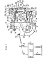
- This invention relates to double lift negative dobby machines, and more particularly to double-lift machines wherein a heald frame is biased downwards by spring action, a tensile element suspending the heald frame is connected to a jack-lever, the center of a balance lever is pivotally attached to the jack lever, the balance lever is provided with driving members corresponding to both ends of the balance lever, and both driving members reciprocate at opposite phases with each other so as to rock the balance lever through hook means and drive the jack lever.
- a heald frame 102 when a heald frame 102 is in the downward position, a rope 103 is placed under tension corresponding to the sum of the tension of a spring 101 and the weight of the heald frame 102, subtracted by an upward combined force based on warp tension; when the heald frame 102 is in the upward position, the rope 103 is under tension corresponding to the sum of the tension of the spring 101 increased because of its elongation during heald frame elevation, the weight of the heald frame 102 and a downward combined force based on warp tension.
- This tension in the rope 103 acts on a connecting portion 105 of a jack-lever 104 which is pivotally connected at its top end 106 to the center of a balance lever 107.
- the contact pieces 108 and 109 are arc-shaped, but the balance lever 107 is pivotally attached to the jack-lever 104 which rocks. During rocking motion of the. balance lever 107 involved in the motion of the jack-lever 104, the contact pieces 108 and 109 engage the stoppers 110 and 111, not by simple rolling contacts but by sliding contacts. Moreover, since the contact is line contact, the load per unit area becomes larger, resulting in abrasion at contact regions.
- the knives 112 and 113 are held substantially in the horizontal direction, but they are pivotally attached to the upper and lower ends of a rocking lever 116 which is supported at its center. Accordingly, the motion of the knives 112, 113 and that of the pivotal portions of the hook levers 114, 115 follow respective circular arcs having differing radii. Therefore, variation of contact state occurs at engaging portions between hooks of the hook levers 114, 115 and the knives 112, 113. This also causes abrasion in contact portions.
- the dobby machine of this type has the disadvantage that abrasion of working parts causes rapid reduction of function.
- control rods 117 and 118 controlling the hook levers 114 and 115 or the like are interposed between the knives and the balance lever.
- the distance between the knives and the balance lever must be sufficiently large whereby the hook lever becomes longer than is required for working. This obstructs high-speed operation and requires a larger installation area.
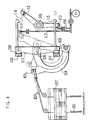
- Fig. 5 shows another example of known dobby machine.
- the spring 101, the heald frame 102, the rope 103, the jack lever 104 or the like are constituted similarly to Fig. 4.
- the center of a balance lever 120 is pivotally attached at 119 to the jack lever 104, and hook levers 121 and 122 are pivotally attached to both ends of the balance lever 120.
- a rocking lever 123 is provided with a rocking shaft concentric to the pivotal shaft 119 of the balance lever.
- Driving members 124 and 125 fixed to both ends of the rocking lever 123 face base portions of the hook levers 121 and 122 respectively.
- the driving members 124 and 125 push against base portions of the hook levers 121 and 122, when the heald frame 102 is in the downward position.
- Stopping hook levers 126 and 127 are pivotally attached to shafts fixed on the machine casing.
- Command arms 128 and 129 are pivotally mounted in concentric relation and connected with each other through a spring. The command arms 128 and 129 work in response to pegs on a peg card. For example, the rocking lever 123 is rotated counter-clockwise and the hook lever 122 is engaged with the stopping hook lever 127. If the rocking lever 123 is rotated clockwise in this state, the balance lever 120 is rotated clockwise about the pivotal shaft of the hook lever 122 and the jack-lever 104 is also rotated clockwise whereby the heald frame 102 rises.
- the balance lever 120 rocks integral with the rocking lever 123 about the pivot 119 of the jack lever 103. In this state, tension in the rope 103 transmits a reaction force to the pivot 119 through a connecting portion. If one of a plurality of heald frames 102 is not used corresponding to textile pattern, the jack lever 104 and the balance lever 120 corresponding to the unused heald frame 102 are rocked under the load at the pivot. Accordingly, abrasion may occur in the jack lever 104 and the balance lever 120 in similar manner to those corresponding to the used heald frame 102.
- Dobby machines of the general type shown in Figure 5 herein are also disclosed in US-A-3 441 060, US-A-4,182,380 and FR-A-2,428,693.
- these known constructions of double lift negative dobby machine have a mechanism to control the raising and lowering of a heald frame via a tensile element, and comprise a pivotally mounted jack lever, a balance lever pivotally connected to the jack lever, driving members arranged to co-operate with opposite ends of the balance lever and to reciprocate in opposite directions relative to each other, first hook levers pivotally connected to the opposite ends of the balance lever and engageable by second hook levers, each first hook lever having a hook at one end for engaging with a respective hook of the second levers and a flat contact surface at an opposite end, and means having plane contact surfaces arranged to contact the flat surfaces of the first hook levers.
- the present invention has been developed with a view to improve the above known constructions of double lift negative dobby machine, by providing features which enable abrasion of the jack lever and the balance lever corresponding to an unused heald frame to be obviated.
- a double lift negative dobby machine having a mechanism to control the raising and lowering of a heald frame via a tensile element and comprising a pivotally mounted jack lever, a balance lever pivotally connected to the jack lever, driving members arranged to co-operate with opposite ends of the balance lever and to reciprocate in opposite directions relative to each other, first hook levers pivotally connected to said opposite ends of the balance lever and engageable by second hook levers, each first hook lever having a hook at one end for engaging with a respective hook of the second levers and a flat contact surface at an opposite end, and means having plane contact surfaces arranged to contact the flat surfaces of the first hook levers: characterised in that the second hook levers are pivotally connected to said driving members, and said means having plane contact surfaces for contacting the flat surfaces of the first hook levers are stops fixed to the casing of the machine.
- a dobby machine having a balance lever provided with two driving members corresponding to both ends of the balance lever (the driving members reciprocating in opposite phases with each other), second hook levers rotatably fitted to the driving members and corresponding to the balance lever, and first hook levers engageable with the second hook levers and pivotally attached to both ends of the balance lever.
- the reaction force produced at both ends of the balance lever of a tensile element connected to the heald frame, when the latter is in its lowered position, is applied against stops having plane contact surfaces by means of flat surfaces provided on the first hook levers.
- the first hook levers are arranged in predetermined attitudes, during the pushing state of the flat surfaces against the stops, and command for the upward and downward motion of the heald frame is transmitted by angular displacement of the second hook levers which are rotatably fitted to two driving members which reciprocate in opposite phases, and by engaging or releasing the second hook levers with corresponding first hook levers.
- Command is achieved by command levers having bell crank shape which are pivotally attached to shafts fixed to the machine casing.
- Each command lever is arranged to have resilient contact with its respective second hook lever, and the command levers are operated by pegs of a peg card which is rotated, or by a horizontal lever for a paper card.
- the dobby machine comprises a tension coil spring 1, a heald frame 2, guide rollers 3, a rope or ropes 4 (tensile elements), and a jack lever 5, each member being as in conventional negative dobby machines.
- the lower end of the spring 1 is connected to a casing (not shown) of a loom, the guide rollers 3 are fitted to shafts fixed on the casing, the base portion of the jack lever 5 is rotatably fitted to a shaft 6 fixed on the casing (not shown) of the dobby machine, and the rope 4 is engaged wtih a hook 5a.
- a balance lever 8 is connected to the top end of the jack lever 5 via a pin 7, and is arranged in vertical symmetry with respect to the pin 7.
- An upper first hook lever 10 is pivotally connected to the top end of the balance lever 8 through a respective one of pins 9.
- the hook lever 10 is provided with a hook 10a at its right end and a flat surface 10b at its left hand end (as seen in Fig. 1).
- An extension of the line connecting the center of the hook 10a to the axial center of the pin 9 is perpendicular to the flat surface 10b at the center thereof.
- a lower first hook lever 11 in vertical symmetry to the upper first hook lever 10 is pivotally connected to the lower end of the balance lever 8 through a respective pin 9.
- An upper stop 12 and a lower stop 13 are fixed to the casing (not shown) so that the balance lever 8 is held in the vertical direction when the heald frame 2 is at the downward position.
- the right hand side of the stops 12 and 13 are located in the same vertical plane as the flat surfaces of the hooks 10, 11 which engage them.
- a line connecting the center of the hook with the axial center of the respective pin 9 extends horizontally when the heald frame 2 is held at the downward position.
- a shaft 14 is attached to the casing (not shown) at the right hand side, and at the same level as the pin 7 (in the downward state of the heald frame 2).
- the shaft 14 reciprocates one time in a prescribed angular motion during each two revolutions of the loom.
- a lever 15 is fixed to the shaft 14 and has limbs which extend upwardly and downwardly from the shaft 14 and are inclined to each other at a prescribed angle.
- An upper driving member 16 and a lower driving member 17 are fixed respectively to the upper and lower ends of the lever 15.
- the driving members 16 and 17 have circular cross- sections of the same diameter, and the distance from the axial center of the driving member 16 to the shaft 13, and from the member 17 to the shaft 14, have the same length equal to one half of the distance between the pins 9 at each end of the balance lever 8.
- the axial center of the lower driving member 17 is located below the axial center of the shaft 14 in a common vertical plane, when the shaft 14 is rotated clockwise (see Fig. 1); the axial center of the upper driving member 16 is located above the axial center of the shaft 14 in a common vertical plane, when the shaft 14 is rotated counterclockwise (see Fig. 2).
- a lower second hook lever 19 is fitted to the lower driving member 17 so that it may be rotated about the driving member 17 and engaged with the lower first hook lever 11.
- the lower second hook lever 19 is provided with a hook 19a at its left hand end and a cutaway portion 19b at its right hand end.
- the hook 19a faces the hook 11 a of the lower first hook lever 11 (which push against the lower stop 13), a prescribed gap being provided between the hooks 19a and 11 b, so that the axial center of the lower pin 9, the center portion of the hook 19a, the center portion of the hook 11 a and the axial center of the lower driving member 17 are arranged in a line.
- An upper second hook lever 18 is symmetrical to the lower second hook lever 19 in the vertical direction.
- a cutaway portion 18b of the hook lever 19 receives an upper stopper bar 20 which extends horizontally (perpendicular to the drawing).
- the stopper bar 20 is so arranged that a hook 18a of the hook lever 18 rocks approximately along a horizontal line.
- a tension coil spring 28 connected to the right hand end of the hook lever 18, a prescribed vertical gap is provided between the 'hook 18a and the hook 10a and the hook lever 18 may be rocked laterally.
- a lower stopper bar 21 is arranged symmetrical to the upper stopper bar 20 in the vertical direction.
- the lower stopper bar 21 faces the upper side of the cutaway portion 19b of the lower driving hook lever 19.
- the stopper bar 21 defines the attitude adopted by the driving hook lever 19 so that a prescribed gap is provided between the hook 19a and the hook 11 a and the hook lever 19 may be rocked.
- Blocks 22, 23 (to which the stopper bars 20, 21 are fixed), are rotatably fitted to the upper driving member 16 and the lower driving member 17 respectively.
- One end of a guide rod 24 is fixed to the block 22, and the other end thereof extends leftwards and is guided by a pair of guide rollers 26 which are supported by the casing.
- a guide rod 25 symmetrical to the block 22 in the vertical direction is guided by a pair of guide rollers 27 (also supported by the casing).
- the upper and lower tension coil springs 28 are anchored by pins 29, 30 which are fixed to the blocks 22, 23 respectively.
- Fixing shafts 31, 32 are fixed to the casing, symmetrically in the vertical direction to the right of the shaft 14.
- An upper command lever 33 is adjacent to the upper second hook lever 18 and is loosely connected to the fixing shaft 31.
- the command lever 33 is of inverted L-shape, having a horizontal portion extended by a leaf spring arm 34 which has its free end bent to form a pushing portion 34a of arc shape.
- the pushing portion 34a is disposed substantially vertically below the hook 10a of the upper driven hook lever 10 when the hook lever 10 pushes against the stopper 12.
- a vertical portion of the command lever 33 extends downwards and faces a peg as hereinafter described.
- a lower command lever 35 and a leaf spring arm 36 are symmetrical respectively to the upper command lever 33 and the leaf spring arm 34 in the vertical direction.
- the command levers 33 and 35 are biased by a tension coil spring 37 which connects the horizontal portions of the levers 33 and 35 with each other, and biases them towards stopper shafts 38 and 39 disposed symmetrical to the casing in the vertical direction, so that the pushing portions 34a and 36a are spaced by a prescribed gap respectively from the second hook levers 18 and 19 being rocked.
- a card cylinder shaft 40 is supported by the casing at the same level as the shaft 14 and is rotated in association with the rocking motion of the shaft 14.
- a card cylinder 41 is fixed to the card cylinder shaft 40, and a known endless peg card is circulated by rotating the card cylinder 41.
- the peg card is provided with pegs e.g. a peg 42 extending outwards from the card surface.
- the hook 18a When the second hook lever 18 is moved leftwards, the hook 18a is located adjacent to the hook 10a of the upper first hook lever 10 (pushing against the stop 12).
- the lower command lever 35 is also pushed by the peg 42 so as to rotate the lower second hook lever 19 in similar manner to the upper second hook lever 18.
- the pin 9, the hook 11 a, the hook 19a and the driving member 17 are aligned even during movement by means of resistance, the engaging state between the hooks 11 a and 19a does not vary and the sliding action does not occur.
- the balance lever 8 is rotated about the pin 9 and therefore does not slide over a narrow area. Limited sliding action does occur between the right hand side surface of the upper stop 12 and the flat surface 10b, corresponding to the amount of vertical displacement accompanying the arcuate motion of the pin 7, but the amount of movement is very small. Furthermore, the load per unit area is small because of contact via flat surfaces.
- the pin 7 is rocked preferably between symmetrical positions with respect to a vertical line passing through the axial center of the shaft 6, in order to decrease the amount of sliding between the stops 12, 13 and the flat surfaces 1 Ob, 11 b,
- the lower second hook lever 19 rocks leftwards, the contacting state between the hooks 11 a and 19a does not vary and the balance lever 8 is restored by rotation about the upper pin 9 as fulcrum in similar manner to the case of the rightward rocking.
- the upper command lever 33 is rotated clockwise by the peg 42, the upper second hook lever 18 works like the lower second hook lever 19 and elevates the heald frame 2 via the upper first hook lever 10, the balance lever 8 and the jack lever 5.
- the peg 42 will not be arranged in a position opposite to the command lever corresponding to an unused heald frame 2, the upper second hook lever 18 and the lower second hook lever 19 are not rotated. therefore the balance lever 8 is held in the vertical position (Fig. 1) by the stops 12, 13 via flat surfaces of the first hook levers 10, 11, whereby the (unused) heald frame is held at the downward position. Accordingly, rotating motion does not occur at the pivot 7, between the balance lever 8 and the jack-lever 5. Since the stopper bars 20, 21 and pins 29, 30 are fixed to the blocks 22, 23 and move approximately in parallel motion, the horizontal and vertical position with respect to the driving members 16, 17 is held approximately constant irrespective of position of the rocking arms. Thereby the second hook levers 18, 19 are rocked in parallel movement when the cutaway portions 18b, 19b push against the stoppers 20, 21 respectively.
- Fig. 3 there is shown an alternative construction of command levers to be operated by a control device A.
- the leaf spring arms 34, 36 are operated selectively to displace the respective second hook lever 18 upwardly or lever 19 downwardly via control device A, mechanism 43 and the respective crank arm 44 or 45.
- the mechanism 43 is operated by the control device A so as to pivot the required crank arm 44 or 45.
Landscapes
- Engineering & Computer Science (AREA)
- Textile Engineering (AREA)
- Looms (AREA)
- Jib Cranes (AREA)
Claims (6)
Applications Claiming Priority (2)
| Application Number | Priority Date | Filing Date | Title |
|---|---|---|---|
| JP55013971A JPS6017859B2 (ja) | 1980-02-07 | 1980-02-07 | 消極複動ドビ−機 |
| JP13971/80 | 1980-02-07 |
Publications (2)
| Publication Number | Publication Date |
|---|---|
| EP0034045A1 EP0034045A1 (fr) | 1981-08-19 |
| EP0034045B1 true EP0034045B1 (fr) | 1984-06-06 |
Family
ID=11848102
Family Applications (1)
| Application Number | Title | Priority Date | Filing Date |
|---|---|---|---|
| EP81300486A Expired EP0034045B1 (fr) | 1980-02-07 | 1981-02-05 | Mécanique d'armure à double levée commandé négativement |
Country Status (5)
| Country | Link |
|---|---|
| US (1) | US4386631A (fr) |
| EP (1) | EP0034045B1 (fr) |
| JP (1) | JPS6017859B2 (fr) |
| DE (1) | DE3162630D1 (fr) |
| ES (1) | ES499219A0 (fr) |
Families Citing this family (9)
| Publication number | Priority date | Publication date | Assignee | Title |
|---|---|---|---|---|
| US4474221A (en) * | 1982-09-16 | 1984-10-02 | Yamada Dobby Co., Ltd. | Positive dobby machine |
| JPS61637A (ja) * | 1984-06-11 | 1986-01-06 | 村田機械株式会社 | ドビ−機における読取装置 |
| JPS6175838A (ja) * | 1984-09-18 | 1986-04-18 | 村田機械株式会社 | ドビ−機における読取装置 |
| FR2647124B1 (fr) * | 1989-05-19 | 1991-07-12 | Staubli Sa Ets | Ratiere negative a balances oscillantes pour metiers a tisser |
| FR2651803B1 (fr) * | 1989-09-14 | 1991-11-08 | Staubli Sa Ets | Ratiere a double leve du type a balances tirees pour machines a tisser. |
| FR2662185B1 (fr) * | 1990-05-16 | 1992-08-28 | Staubli Ste | Systeme pour l'amarrage des cables de tirage sur les leviers de suspension des ratieres textiles du type negatif. |
| JP3425983B2 (ja) * | 1992-12-25 | 2003-07-14 | 株式会社山田ドビー | ドビー |
| KR100438232B1 (ko) * | 2001-05-28 | 2004-07-02 | 구본성 | 도비직기용 도비기의 리프스프링 |
| US20060184199A1 (en) * | 2005-02-14 | 2006-08-17 | O'leary Shawn | Apparatus and methods for reducing bleeding from a cannulation site |
Citations (2)
| Publication number | Priority date | Publication date | Assignee | Title |
|---|---|---|---|---|
| US3441060A (en) * | 1966-10-07 | 1969-04-29 | Staubli Geb & Co | Double lift dobbies |
| US4182380A (en) * | 1977-05-27 | 1980-01-08 | Societe Anonyme Des Etablissments Staubli | Dobbies for weaving looms |
Family Cites Families (4)
| Publication number | Priority date | Publication date | Assignee | Title |
|---|---|---|---|---|
| GB651848A (en) * | 1942-10-03 | 1951-04-11 | Fumat S A Ets | Dobby operating with a paper pattern |
| US3285291A (en) * | 1965-10-01 | 1966-11-15 | Staubli Geb & Co | Drive-mechanism in double lift dobbies |
| FR2428693A1 (fr) * | 1978-06-16 | 1980-01-11 | Staubli Sa Ets | Perfectionnements aux dispositifs de lisage pour ratieres ou autres mecaniques de tissage |
| CH635874A5 (de) * | 1979-02-13 | 1983-04-29 | Staeubli Ag | Gegenzug-schaftmaschine. |
-
1980
- 1980-02-07 JP JP55013971A patent/JPS6017859B2/ja not_active Expired
-
1981
- 1981-02-05 DE DE8181300486T patent/DE3162630D1/de not_active Expired
- 1981-02-05 EP EP81300486A patent/EP0034045B1/fr not_active Expired
- 1981-02-06 ES ES499219A patent/ES499219A0/es active Granted
- 1981-02-09 US US06/232,421 patent/US4386631A/en not_active Expired - Fee Related
Patent Citations (2)
| Publication number | Priority date | Publication date | Assignee | Title |
|---|---|---|---|---|
| US3441060A (en) * | 1966-10-07 | 1969-04-29 | Staubli Geb & Co | Double lift dobbies |
| US4182380A (en) * | 1977-05-27 | 1980-01-08 | Societe Anonyme Des Etablissments Staubli | Dobbies for weaving looms |
Also Published As
| Publication number | Publication date |
|---|---|
| EP0034045A1 (fr) | 1981-08-19 |
| ES8205895A1 (es) | 1982-06-16 |
| JPS6017859B2 (ja) | 1985-05-07 |
| US4386631A (en) | 1983-06-07 |
| ES499219A0 (es) | 1982-06-16 |
| JPS56112532A (en) | 1981-09-04 |
| DE3162630D1 (en) | 1984-07-12 |
Similar Documents
| Publication | Publication Date | Title |
|---|---|---|
| EP0034045B1 (fr) | Mécanique d'armure à double levée commandé négativement | |
| JPH10183442A (ja) | 織成機構の選択装置及びスリーポジション式ジャカー ドの織成機構並びにそのような織成機構を備えた織機 | |
| KR100403262B1 (ko) | 개구형성기계의이동훅을선택하는방법,선택하는장치및이동훅이설치된쟈카드타입직기 | |
| JPS6262945A (ja) | 傾動する固定フックを有する織機のひ口形成装置 | |
| US3441060A (en) | Double lift dobbies | |
| EP0699787B1 (fr) | Appareil pour la sélection de dispositif de formation de la foule au moyen d'élléments déformables | |
| US7490633B2 (en) | Shed-forming mechanism, a loom fitted with such a mechanism, and a method of selecting moving hooks in such a mechanism | |
| US3884272A (en) | Double-lift open-shed jacquard machine | |
| US3938560A (en) | Apparatus for the mechanical operation of thread or yarn guides | |
| KR920006557A (ko) | 전자적으로 작동되는 자카드 제어장치 | |
| US3951176A (en) | Hook connecting apparatus in a chain disc-type dobby machine | |
| KR0139102B1 (ko) | 제직기용 도비 | |
| US4481979A (en) | Heald frame driving method in negative dobby machines or cam machines | |
| US4474221A (en) | Positive dobby machine | |
| US4832087A (en) | Negative dobbies of the type incorporating swinging levers | |
| US4685492A (en) | Reading device in dobby machine | |
| US5365979A (en) | Dobby for electromagnetically controlling a heald frame | |
| US4603713A (en) | Lifting device for a heddle frame | |
| KR840001903B1 (ko) | 소극복동(消極複動)도비기 | |
| EP0084570A1 (fr) | Machine a ratiere postive | |
| US4296782A (en) | Double-lift open-shed Jacquard machine | |
| US5316049A (en) | Locking mechanisms for selective retention of oscillating levers engaged by knives in a dobby | |
| EP0071943B1 (fr) | Dispositif pour enlever le jeu dans les commandes de ratières d'un métier à tisser | |
| US6116293A (en) | Electromagnetic shed forming apparatus for a jacquard machine | |
| US3459236A (en) | Dobby machines |
Legal Events
| Date | Code | Title | Description |
|---|---|---|---|
| PUAI | Public reference made under article 153(3) epc to a published international application that has entered the european phase |
Free format text: ORIGINAL CODE: 0009012 |
|
| AK | Designated contracting states |
Designated state(s): BE CH DE FR GB IT |
|
| RBV | Designated contracting states (corrected) |
Designated state(s): BE CH DE FR GB IT LI |
|
| 17P | Request for examination filed |
Effective date: 19811015 |
|
| KL | Correction list |
Free format text: 82/01 RECHERCHENBERICHT |
|
| ITF | It: translation for a ep patent filed | ||
| GRAA | (expected) grant |
Free format text: ORIGINAL CODE: 0009210 |
|
| AK | Designated contracting states |
Designated state(s): BE CH DE FR GB IT LI |
|
| REF | Corresponds to: |
Ref document number: 3162630 Country of ref document: DE Date of ref document: 19840712 |
|
| ET | Fr: translation filed | ||
| PLBE | No opposition filed within time limit |
Free format text: ORIGINAL CODE: 0009261 |
|
| STAA | Information on the status of an ep patent application or granted ep patent |
Free format text: STATUS: NO OPPOSITION FILED WITHIN TIME LIMIT |
|
| 26N | No opposition filed | ||
| ITTA | It: last paid annual fee | ||
| PGFP | Annual fee paid to national office [announced via postgrant information from national office to epo] |
Ref country code: GB Payment date: 19921201 Year of fee payment: 13 |
|
| PGFP | Annual fee paid to national office [announced via postgrant information from national office to epo] |
Ref country code: FR Payment date: 19921216 Year of fee payment: 13 |
|
| PGFP | Annual fee paid to national office [announced via postgrant information from national office to epo] |
Ref country code: BE Payment date: 19930104 Year of fee payment: 13 |
|
| PGFP | Annual fee paid to national office [announced via postgrant information from national office to epo] |
Ref country code: DE Payment date: 19930114 Year of fee payment: 13 |
|
| PGFP | Annual fee paid to national office [announced via postgrant information from national office to epo] |
Ref country code: CH Payment date: 19930226 Year of fee payment: 13 |
|
| PG25 | Lapsed in a contracting state [announced via postgrant information from national office to epo] |
Ref country code: GB Effective date: 19940205 |
|
| PG25 | Lapsed in a contracting state [announced via postgrant information from national office to epo] |
Ref country code: LI Effective date: 19940228 Ref country code: CH Effective date: 19940228 Ref country code: BE Effective date: 19940228 |
|
| BERE | Be: lapsed |
Owner name: YAMADA DOBBY CO. LTD Effective date: 19940228 |
|
| GBPC | Gb: european patent ceased through non-payment of renewal fee |
Effective date: 19940205 |
|
| PG25 | Lapsed in a contracting state [announced via postgrant information from national office to epo] |
Ref country code: FR Effective date: 19941031 |
|
| REG | Reference to a national code |
Ref country code: CH Ref legal event code: PL |
|
| PG25 | Lapsed in a contracting state [announced via postgrant information from national office to epo] |
Ref country code: DE Effective date: 19941101 |
|
| REG | Reference to a national code |
Ref country code: FR Ref legal event code: ST |