EP0034073B1 - Kreuzgelenke - Google Patents
Kreuzgelenke Download PDFInfo
- Publication number
- EP0034073B1 EP0034073B1 EP81400057A EP81400057A EP0034073B1 EP 0034073 B1 EP0034073 B1 EP 0034073B1 EP 81400057 A EP81400057 A EP 81400057A EP 81400057 A EP81400057 A EP 81400057A EP 0034073 B1 EP0034073 B1 EP 0034073B1
- Authority
- EP
- European Patent Office
- Prior art keywords
- walls
- universal joint
- joint according
- rollers
- raceways
- Prior art date
- Legal status (The legal status is an assumption and is not a legal conclusion. Google has not performed a legal analysis and makes no representation as to the accuracy of the status listed.)
- Expired
Links
- 230000005489 elastic deformation Effects 0.000 claims description 11
- 239000002184 metal Substances 0.000 claims description 6
- 239000013536 elastomeric material Substances 0.000 claims description 4
- 229910000639 Spring steel Inorganic materials 0.000 claims description 3
- 239000000463 material Substances 0.000 claims description 3
- 229920003023 plastic Polymers 0.000 claims description 3
- 239000004033 plastic Substances 0.000 claims description 3
- 239000000853 adhesive Substances 0.000 claims 1
- 238000004026 adhesive bonding Methods 0.000 claims 1
- 230000001070 adhesive effect Effects 0.000 claims 1
- 238000003825 pressing Methods 0.000 claims 1
- 229910000831 Steel Inorganic materials 0.000 description 3
- 239000010959 steel Substances 0.000 description 3
- 238000002788 crimping Methods 0.000 description 2
- 238000013016 damping Methods 0.000 description 2
- 238000001914 filtration Methods 0.000 description 2
- 239000002436 steel type Substances 0.000 description 2
- 229910001209 Low-carbon steel Inorganic materials 0.000 description 1
- 230000008878 coupling Effects 0.000 description 1
- 238000010168 coupling process Methods 0.000 description 1
- 238000005859 coupling reaction Methods 0.000 description 1
- 230000006866 deterioration Effects 0.000 description 1
- 230000000694 effects Effects 0.000 description 1
- 238000009413 insulation Methods 0.000 description 1
- 238000002955 isolation Methods 0.000 description 1
- 239000007779 soft material Substances 0.000 description 1
Images


Classifications
-
- F—MECHANICAL ENGINEERING; LIGHTING; HEATING; WEAPONS; BLASTING
- F16—ENGINEERING ELEMENTS AND UNITS; GENERAL MEASURES FOR PRODUCING AND MAINTAINING EFFECTIVE FUNCTIONING OF MACHINES OR INSTALLATIONS; THERMAL INSULATION IN GENERAL
- F16D—COUPLINGS FOR TRANSMITTING ROTATION; CLUTCHES; BRAKES
- F16D3/00—Yielding couplings, i.e. with means permitting movement between the connected parts during the drive
- F16D3/16—Universal joints in which flexibility is produced by means of pivots or sliding or rolling connecting parts
- F16D3/20—Universal joints in which flexibility is produced by means of pivots or sliding or rolling connecting parts one coupling part entering a sleeve of the other coupling part and connected thereto by sliding or rolling members
- F16D3/202—Universal joints in which flexibility is produced by means of pivots or sliding or rolling connecting parts one coupling part entering a sleeve of the other coupling part and connected thereto by sliding or rolling members one coupling part having radially projecting pins, e.g. tripod joints
- F16D3/205—Universal joints in which flexibility is produced by means of pivots or sliding or rolling connecting parts one coupling part entering a sleeve of the other coupling part and connected thereto by sliding or rolling members one coupling part having radially projecting pins, e.g. tripod joints the pins extending radially outwardly from the coupling part
- F16D3/2055—Universal joints in which flexibility is produced by means of pivots or sliding or rolling connecting parts one coupling part entering a sleeve of the other coupling part and connected thereto by sliding or rolling members one coupling part having radially projecting pins, e.g. tripod joints the pins extending radially outwardly from the coupling part having three pins, i.e. true tripod joints
Definitions
- the invention relates to a universal joint of the kind which includes an internal element, integral with a first shaft, having at least two pins, regularly spaced, which carry rollers, the external surface of which is a clean spherical zone. to cooperate with raceways with hard walls, provided in an external element made integral with a second shaft, this external element comprising a rigid envelope provided with housings in which the raceways are located, elastic means being provided in connection with these raceways.
- the document FR-A-1 409 909 shows a universal joint of this kind in which the roller tracks of the rollers are formed by linings in a material resistant to wear more than the metal of the housing in which the housings are provided. these toppings and for the pebbles.
- Document FR-A-2 000 790 shows a universal joint of a different kind from that defined above since, on the one hand, the rollers have a cylindrical outer surface and, on the other hand, these rollers cooperate with a gasket. rubber, i.e. a soft material with respect to steel or the like.
- the object of the invention is, above all, to provide a universal joint of the kind defined above which practically makes it possible to eliminate the clearances between rollers and raceways and to obtain good noise insulation, while remaining simple and economical and while having qualities of robustness and lightness.
- a universal joint of the kind defined above is characterized in that the assembly is arranged in such a way that the elastic means tend to apply the hard walls of the raceways against the rollers, each roller being clamped between the two hard walls delimiting a raceway, these hard walls being kept constantly in pressure against the rollers by the elastic means.
- said external element comprises several rigid plates conformed at least partially to the rollers and arranged so that each raceway is delimited by two separate plates, the above elastic means being formed by elastic connecting members between each plate and the walls of the housings.
- An elastic member is associated with each plate, the elastic members associated with the same raceway being independent of each other.
- the elastic members can be formed by blocks, in particular of elastomeric material, the inner surface of which is linked, in particular by bonding or adhesion, to the above-mentioned plates, while their outer surface is linked to the wall of the housings.
- the rigid plates delimiting a raceway are located on each side of a plane passing through the axis of the external element and that of the raceway considered.
- the external element consists of a piece of tubular metal sheet, comprising bosses corresponding to the housings, these bosses extending along the length of the tubular piece and having two walls substantially parallel to a plane passing through the 'axis of the envelope and the axis of the raceway associated with the housing.
- Each rigid plate can be formed by a sheet metal plate, of length substantially equal to that of the envelope; the rigid plate having a partially cylindrical concave surface with a radius equal to the radius of the rollers.
- the elastic blocks associated with two neighboring rollers and included, angularly, between these two rollers are connected to each other so as to form a single block; advantageously, the rigid plates associated with two neighboring rollers and included angularly between these two rollers are integral with one another.
- the elastic blocks grouped two by two form three identical blocks substantially V-shaped and respectively arranged astride, by the internal faces of the V, on two adjacent sides of two bosses.
- the external element comprises a tubular part attached to the interior of the rigid envelope and the walls of which delimit the raceways, this tubular part comprising means suitable for allowing transverse elastic deformation of said walls , which have a transverse elasticity, and constitute, at least in part, the above elastic means.
- the means suitable for allowing transverse elastic deformation of the walls limiting the raceways can be formed by longitudinal openings separating the neighboring end edges of walls limiting the neighboring raceways, the two walls limiting the same raceway being connected together so as to form a receptacle, this receptacle being itself -Even linked to the tubular part along a longitudinal strip, in its zone furthest radially from the axis of the universal joint.
- the walls delimiting the same raceway can be formed by two parts of the tubular part cut on either side of the said longitudinal strip, the cut parts being folded and deformed so as to constitute the above walls, the length of the cut parts being lower than that of the tubular part so that a belt, completely closed, remains at each longitudinal end of the tubular part.
- a longitudinal bar remains in the spaces freed up after cutting and folding of two walls corresponding to two neighboring raceways.
- the two longitudinal end belts of the tubular part have a substantially triangular outline, each of the sides being joined by a portion of a circle to the neighboring side; the longitudinal strip, on either side of which are located the two parts limiting a raceway, is located at each of the portions of circles of the belts.
- the means suitable for allowing transverse elastic deformation of the walls limiting the raceways comprise at least one folding directed outwards, suitable for connecting two walls limiting two different neighboring raceways.
- the tubular part is advantageously made of steel of the spring steel type.
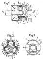
- This seal comprises an interior element A, which is a first shaft 1, or driven shaft, and constituted by a hub 2 having three pins 3, regularly spaced. Each pin carries a roller 4 whose outer surface is a spherical zone.
- rollers 4 are suitable for cooperating with raceways r provided in an external element B.
- This external element B is integral with a part 5, arranged in a clamp, in which a second shaft 6, or driving shaft, is intended to be introduced and blocked.
- This second shaft is thus made integral with the external element B.
- This external element B comprises a rigid envelope 7 provided with housings 8 in which the raceways r are located.
- the rigid envelope 7 is constituted by a piece of tubular metal sheet having, externally, three identical bosses 9, regularly spaced in correspondence with the housings 8.
- Each boss 9 has two walls 9a, 9b, substantially parallel to the plane P passing through the axis of the casing 7 and by that of the raceway r associated with the boss 9.
- the external element B comprises several rigid plates 10, conformed, at least partially, to the rollers 4; each raceway r is delimited by two plates 10 forming tracks, separate and independent from each other. These plates are located on each side of the plane P.
- the zones of the plates conformed to the rollers have concave cylindrical surfaces 11 with a radius substantially equal to that of the rollers 4.
- the rigid plates 10 associated with two adjacent rollers, and included angularly between these two rollers are integral with one another by an intermediate portion 12.
- the assembly of the plates 10 forms three parts monobloc 13, each part comprising two plates 10 connected by the intermediate part 12.
- the adjacent ends of two parts 13 are separated by a space e (FIG. 2) situated radially outwards relative to the end of the pins 3.
- Elastic connecting members are provided between each rigid plate 10 and the walls of the housings 8 of the envelope 7, these members being suitable for applying the plates 10 against the rollers 4.
- the members are formed by elastic blocks 14, in particular made of elastomeric material, the inner surface of which is bonded by adhesion or bonding, to the plates 10, while their outer surface is linked, also by adhesion or bonding, to the walls of the housings 8.
- the elastic blocks 14, associated with two neighboring rollers 4 and included, angularly, between these two rollers, are connected l to each other by an intermediate part 15 so as to form a single elastic block 16.
- This block 16 has substantially the shape of a V and is arranged astride, from the inside of the branches of the V, as visible on FIG. 2, on two adjacent sides of two bosses 9. The outside of the block 16 is adhered to the part 13.
- the elastic blocks 16 associated with each part 13 are independent of each other and also separated by the space e as visible in FIG. 2. These blocks extend along the entire length of the parts 13, as visible on the figure 1.
- the assembly is such that, when the seal is mounted, that is to say when the rollers 4 are introduced into the two plates 10 delimiting the path r, these plates being kept constantly in pressure against the rollers by the elastic blocks 14, 16.
- the tubular casing 7 can, according to a first solution shown in FIGS. 1 to 4, be partially crimped by two opposite zones 7a, 7b on the edge of a bottom plate. 17 metallic, circular.
- This plate 17 has, in its central part, a pin 18, on which the shaft 1 is supported.
- the part 5, forming a clamp has two diametrically opposite branches 19, 20 located in a plane perpendicular to the axis of the envelope 7. As can be seen in FIG. 4, these branches cover, at their radial end, both an area 7c of the edge of the enclosure 7 and an area of the plate 17; the radial end of the two branches 19, 20, is crimped onto the stack formed by these two zones.
- the zones 7a, 7b of the casing 7 therefore have a notch to allow crimping of the ends of the branches 19 and 20.
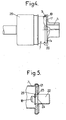
- the tubular casing 7 is crimped around a circular plate 21 mounted on a threaded piece 22 which is integral with the drive shaft 2 (not shown in this figure 5).
- the part 22 comprises the pin 18.
- the circular plate 21 is stopped axially on the part 22, on the one hand, by a split elastic ring 23 engaged in a groove 24 of the part 22 and on the other hand by crimping 25 of the end of part 22.
- a bellows 26 of elastomeric material surrounds the open end of the envelope and the shaft 1.
- rollers 4 are able to cooperate with the raceways r provided in the external element B made integral with the second shaft 6 by the part 5 in the form of a collar.
- This external element B comprises the rigid envelope 7 in the form of a bowl, of substantially triangular cross section; as visible in Figure 7, this cross section has straight sides C connected by portions of a circle D.
- tubular piece 27 comprising walls p delimiting housings forming the raceways r.
- the tubular part 27 comprises means m suitable for allowing transverse elastic deformation of the walls p limiting the raceways r, so that the rollers 4 can be mounted tight between these walls p to avoid any circumferential play between the walls and the pebbles. These walls themselves have a transverse elasticity.
- the walls p delimiting the same raceway can deviate elastically in a direction t (FIG. 7) orthogonal to the mean plane h of the raceway considered, this plane h passing through the axis of the envelope 7.
- the means m suitable for allowing transverse elastic deformation of the walls p are formed by longitudinal openings 0 (fig. 7 and 9) separating the edges f, g, of end close to the walls limiting neighboring raceways.
- the two walls p limiting the same raceway are connected together so as to form a receptacle q; this receptacle is itself linked to the tubular part 27 along a longitudinal strip 28, in its zone most radially distant from the axis of the universal joint.
- the walls p delimiting the same raceway are formed by two parts 29, 30 of the tubular part 27 (see fig. 9) cut on either side of the central longitudinal strip 28 located in the middle of each of the circle portions D. These cut parts 29 and 30 are folded and deformed in order to present a section in an arc.
- the length 1 of the parts 29 and 30 is less than the length L of the tubular part 27 so that a completely closed belt 31a, 31b remains at each longitudinal end of the tubular part 27.
- a longitudinal bar 32 connecting the belts 31a, 31b, as clearly visible in FIG. 9, remains between the spaces freed up after cutting and folding of two walls p corresponding to two neighboring raceways.
- three bars 32 are present and regularly spaced.
- the tubular part 27 is stopped axially, relative to the casing 7, by means of a ring 33 (fig. 6) in particular made of plastic material, comprising lugs 34, suitable for being clipped, that is to say say to be engaged by elastic deformation, in holes 35 of the envelope 7.
- This envelope 7 is made, for example, of low carbon steel which can be easily extruded.
- the tubular part 27 is made of steel of the spring steel type; the width k of the raceways (fig. 9), that is to say the diameter of the fraction of circular section limited by the cut parts 29, 30, in the free state, is substantially less than the diameter d of the rollers 4.
- rollers 4 transmit to the tubular part 27 the rotational movement of the shaft 1, by their action against the raceways; the tubular part 27 transmits this rotational movement to the casing 7 by the contact which is established along the sides C of the part 27; the rotational movement of the shaft 1 is thus transmitted to the shaft 6.
- FIG. 8 shows an alternative embodiment according to which a block E, for example made of plastic, is provided between two walls of adjacent raceways.
- This block is mounted with a clearance j, relative to the wall, so as to limit the elastic deformation of the wall by its abutment against the block.
- the means m suitable for permitting transverse elasticity of the walls p comprise at least one folding 37 produced between each of the housings 36 and suitable for connecting two walls p limiting two neighboring raceways; the folding 37 is directed outwards and has two longitudinal zones 37a, 37b, oriented substantially radially, connected by a rounded zone 38 turning its convexity towards the outside.
- the area 37a is connected to a wall p of a raceway by a rounded area 39 turning its convexity inwards, while the area 37b is connected to the wall p of the neighboring raceway by a rounded area 40 turning also its inward convexity.
- the folding 37 forms a kind of deformable bellows.
- the tubular part 27c can be produced by drawing or deformation.
- a universal joint according to the invention is particularly quiet and free of play since all the play between the rollers and the walls of the raceways is eliminated, even during wear.
- Such a seal provides good vibration isolation, is robust while remaining light. It is simple and economical to produce. It can be used, in particular, in a motor vehicle steering.
- the invention can be applied to seals other than tripod seals, in particular to seals of the bipod type.
Landscapes
- Engineering & Computer Science (AREA)
- General Engineering & Computer Science (AREA)
- Mechanical Engineering (AREA)
- Rolling Contact Bearings (AREA)
- Bearings For Parts Moving Linearly (AREA)
- Steering Controls (AREA)
Claims (19)
Applications Claiming Priority (4)
| Application Number | Priority Date | Filing Date | Title |
|---|---|---|---|
| FR8003092 | 1980-02-12 | ||
| FR8003092A FR2475657A1 (fr) | 1980-02-12 | 1980-02-12 | Perfectionnements aux joints universels |
| FR8025947 | 1980-12-05 | ||
| FR8025947A FR2495714B2 (fr) | 1980-12-05 | 1980-12-05 | Perfectionnements apportes aux joints universels |
Publications (2)
| Publication Number | Publication Date |
|---|---|
| EP0034073A1 EP0034073A1 (de) | 1981-08-19 |
| EP0034073B1 true EP0034073B1 (de) | 1984-05-02 |
Family
ID=26221603
Family Applications (1)
| Application Number | Title | Priority Date | Filing Date |
|---|---|---|---|
| EP81400057A Expired EP0034073B1 (de) | 1980-02-12 | 1981-01-16 | Kreuzgelenke |
Country Status (3)
| Country | Link |
|---|---|
| US (1) | US4507100A (de) |
| EP (1) | EP0034073B1 (de) |
| DE (1) | DE3163329D1 (de) |
Cited By (2)
| Publication number | Priority date | Publication date | Assignee | Title |
|---|---|---|---|---|
| DE4205654C1 (en) * | 1992-02-25 | 1993-07-29 | Gkn Automotive Ag, 5200 Siegburg, De | Synchronised rotary joint for motor vehicle drives - has three circumferentially spaced elastic moulded bodies connecting inner and outer parts |
| DE102016220597A1 (de) * | 2016-10-20 | 2018-04-26 | Volkswagen Aktiengesellschaft | Längswelle für ein Kraftfahrzeug und Verfahren zur Herstellung einer solchen |
Families Citing this family (26)
| Publication number | Priority date | Publication date | Assignee | Title |
|---|---|---|---|---|
| FR2498274B1 (fr) * | 1981-01-16 | 1986-04-04 | Glaenzer Spicer Sa | Accouplement telescopique a galets et ses applications |
| US4605384A (en) * | 1984-03-14 | 1986-08-12 | Gkn Automotive Components Incorporated | Self-aligning tripod joint tulip cover and constant velocity joint incorporating same |
| DE3437782C1 (de) * | 1984-10-16 | 1986-09-04 | Sobhy Labib Dipl.-Ing. 5210 Troisdorf Girguis | Gleichlaufverschiebegelenk |
| FR2629157B1 (fr) * | 1988-03-28 | 1992-06-05 | Glaenzer Spicer Sa | Tulipe a structure composite pour joint de transmission et son procede de realisation |
| FR2655102A1 (fr) * | 1989-11-30 | 1991-05-31 | Glaenzer Spicer Sa | Joint de transmission a fixite axiale. |
| FR2663699B1 (fr) * | 1990-06-21 | 1995-06-09 | Glaenzer Spicer Sa | Corps de joint de transmission et son procede de realisation. |
| FR2667120A1 (fr) * | 1990-09-21 | 1992-03-27 | Glaenzer Spicer Sa | Joint de transmission articule telescopique et procedes pour realiser un element a pistes de coullissement notamment pour un tel joint. |
| US5591084A (en) * | 1990-10-22 | 1997-01-07 | Gkn Glaenzer Spicer | Transmission joint body portion having an envelope with interior peripheral surface portions extending opposite to and contoured substantially the same as opposite rear surfaces of bearing tracks |
| DE4039597A1 (de) * | 1990-12-12 | 1992-06-17 | Gkn Automotive Ag | Tripodengelenk |
| DE4142359C2 (de) * | 1991-05-31 | 1996-12-12 | Ntn Toyo Bearing Co Ltd | Außenring für ein vibrationsgeschütztes homokinetisches Gelenk |
| DE4142214C2 (de) * | 1991-12-20 | 1997-07-03 | Loehr & Bromkamp Gmbh | Tripodegelenk |
| DE4217332C2 (de) * | 1992-05-26 | 1995-08-03 | Gkn Automotive Ag | Tripodegelenk |
| FR2694058B1 (fr) * | 1992-07-24 | 1994-10-14 | Glaenzer Spicer Sa | Joint de transmission du type à fixité axiale. |
| DE4411515C1 (de) * | 1994-04-02 | 1995-08-03 | Gkn Automotive Ag | Gelenkaußenteil für ein Gleichlaufdrehgelenk und Verfahren zu dessen Herstellung |
| DE4430514C2 (de) * | 1994-08-27 | 1997-02-20 | Gkn Automotive Ag | Gleichlaufdrehgelenk |
| GB9513575D0 (en) * | 1995-07-04 | 1995-09-06 | Gkn Technology Ltd | Tripode type constant velocity ratio universal joints |
| MY125713A (en) * | 1997-02-10 | 2006-08-30 | Honda Motor Co Ltd | Constant velocity universal joint |
| DE19713597C2 (de) * | 1997-04-02 | 1999-06-02 | Gkn Loebro Gmbh | Gelenkaußenteil eines Gleichlaufdrehgelenks |
| DE19819615C2 (de) * | 1998-05-04 | 2001-03-29 | Gkn Loebro Gmbh | Gleichlaufverschiebegelenk mit Demontagesicherung |
| JP4361351B2 (ja) * | 2003-11-14 | 2009-11-11 | Ntn株式会社 | トリポード型等速自在継手 |
| US7147564B2 (en) * | 2004-06-23 | 2006-12-12 | American Axle & Manufacturing, Inc. | Universal joint assembly |
| US7297067B1 (en) * | 2004-12-08 | 2007-11-20 | Gkn Driveline North America, Inc. | Plug and method of retaining the same |
| FR2879279B1 (fr) * | 2004-12-15 | 2007-01-26 | Trelleborg Prodyn Soc Par Acti | Manchon polylobe de protection de transmission de vehicule |
| US7611415B1 (en) * | 2005-01-19 | 2009-11-03 | Gkn Driveline North America, Inc. | Shaft assembly with integrated constant velocity joint |
| US7887422B2 (en) * | 2007-08-02 | 2011-02-15 | American Axle & Manufacturing, Inc. | Universal joint with bearing cup retention mechanism |
| DE102007054563B4 (de) * | 2007-11-15 | 2014-12-18 | Volkswagen Ag | Tripodegelenk |
Family Cites Families (15)
| Publication number | Priority date | Publication date | Assignee | Title |
|---|---|---|---|---|
| US2057875A (en) * | 1936-01-16 | 1936-10-20 | Dallas B Benham | Universal joint |
| US2194798A (en) * | 1936-11-09 | 1940-03-26 | Bendix Prod Corp | Universal joint |
| US2386754A (en) * | 1942-02-05 | 1945-10-16 | Thompson Prod Inc | Universal joint |
| GB565222A (en) * | 1942-02-05 | 1944-11-01 | Thompson Prod Inc | Improvements in and relating to universal joints |
| US2752766A (en) * | 1952-04-04 | 1956-07-03 | Wildhaber Ernest | Laminated mounting and connection, especially for universal joints |
| FR1268917A (fr) * | 1960-10-03 | 1961-08-04 | Brd Co Ltd | Perfectionnements apportés aux joints à rotule |
| FR84753E (fr) * | 1963-01-04 | 1965-04-16 | Citroen Sa Andre | Perfectionnement aux joints homocinétiques |
| FR1352259A (fr) * | 1963-01-04 | 1964-02-14 | Citroen Sa Andre | Perfectionnements aux joints homocinétiques |
| FR1409909A (fr) * | 1964-07-23 | 1965-09-03 | Citroen Sa Andre | Joint universel élastique coulissant pour demi-arbres d'entraînement de roues motrices de véhicules automobiles |
| GB1252889A (de) * | 1968-01-26 | 1971-11-10 | ||
| FR2169450A5 (de) * | 1972-01-25 | 1973-09-07 | Glaenzer Spicer Sa | |
| FR2172580A5 (de) * | 1972-02-18 | 1973-09-28 | Glaenzer Spicer Sa | |
| FR2200923A5 (de) * | 1972-06-01 | 1974-04-19 | Glaenzer Spicer Sa | |
| DE7312997U (de) * | 1973-04-06 | 1973-06-28 | Skf Kugellagerfabriken Gmbh | Tripodegelenk |
| FR2230895A2 (en) * | 1973-05-22 | 1974-12-20 | Glaenzer Spicer Sa | Constant velocity joint with three-arm roller supports - uses flexible bellows seal to achieve compact dimensions |
-
1981
- 1981-01-16 EP EP81400057A patent/EP0034073B1/de not_active Expired
- 1981-01-16 DE DE8181400057T patent/DE3163329D1/de not_active Expired
-
1983
- 1983-08-25 US US06/526,224 patent/US4507100A/en not_active Expired - Lifetime
Cited By (2)
| Publication number | Priority date | Publication date | Assignee | Title |
|---|---|---|---|---|
| DE4205654C1 (en) * | 1992-02-25 | 1993-07-29 | Gkn Automotive Ag, 5200 Siegburg, De | Synchronised rotary joint for motor vehicle drives - has three circumferentially spaced elastic moulded bodies connecting inner and outer parts |
| DE102016220597A1 (de) * | 2016-10-20 | 2018-04-26 | Volkswagen Aktiengesellschaft | Längswelle für ein Kraftfahrzeug und Verfahren zur Herstellung einer solchen |
Also Published As
| Publication number | Publication date |
|---|---|
| DE3163329D1 (en) | 1984-06-07 |
| US4507100A (en) | 1985-03-26 |
| EP0034073A1 (de) | 1981-08-19 |
Similar Documents
| Publication | Publication Date | Title |
|---|---|---|
| EP0034073A1 (de) | Kreuzgelenke | |
| EP0025924B1 (de) | Bedienungsgabel für eine Schaltstange in einem Wechselgetriebe | |
| FR2585096A1 (fr) | Arbre de direction a longueur variable pour dispositifs de direction de vehicules automobiles | |
| EP0321467B1 (de) | Gelenk für eine zusammenklappbare stütze | |
| FR2797014A1 (fr) | Appareil d'accouplement hydrocinetique | |
| FR2490157A1 (fr) | Ensemble de moyeu pour roue motrice de vehicule automobile | |
| EP0980482B1 (de) | Hydrodynamischer drehmomentwandler insbesondere für kraftfahrzeuge | |
| EP0878328A1 (de) | Halbhohlreifen und Walze mit solchen Reifen | |
| FR2783888A1 (fr) | Embrayage de verrouillage pour appareil d'accouplement hydrocinetique et appareil comportant un tel embrayage | |
| FR2748539A1 (fr) | Appareil d'accouplement hydrocinetique a piece d'entrainement de languettes, notamment pour vehicule automobile | |
| FR2787155A1 (fr) | Agencement d'etancheite pour un joint homocinetique, et procede de fabrication correspondant | |
| EP1639267B9 (de) | Vorrichtung und freilaufgehäuse | |
| EP2521866B1 (de) | Kupplungsscheibe und reibungsauskleidung mit an einer folie haftendem reibungsmaterial mit verringerter trägheit | |
| FR2808066A1 (fr) | Appareil d'accouplement hydrocinetique, notamment pour vehicule automobile | |
| FR2584779A1 (fr) | Ensemble mecanique d'etancheite pour pompes | |
| FR2797012A1 (fr) | Appareil d'accouplement hydrocinetique, notamment pour vehicule automobile | |
| FR2876759A1 (fr) | Pallier radial pour l'arbre de transmission d'un vehicule | |
| FR2475657A1 (fr) | Perfectionnements aux joints universels | |
| BE1006669A6 (fr) | Cage pour palier a contact de roulement et palier equipe d'une telle cage. | |
| FR2686671A1 (fr) | Manchette tubulaire a soufflet pour protection d'un joint. | |
| FR2622258A1 (fr) | Dispositif de fixation | |
| FR2776739A1 (fr) | Embrayage de coupure pour un convertisseur hydrodynamique de couple comportant un piston fixe par un element en elastomere | |
| FR2749634A1 (fr) | Amortisseur de torsion pour embrayage de verrouillage, notamment de vehicule automobile | |
| EP0903272B1 (de) | Kraftfahrzeugscheibenwischer mit verbesserter Vorrichtung für die Gelenkverbindung zwischen einem Wischblatt und einem Wischarm | |
| FR2627572A1 (fr) | Dispositif d'etancheite pour joint a emboitement entre deux tuyaux |
Legal Events
| Date | Code | Title | Description |
|---|---|---|---|
| PUAI | Public reference made under article 153(3) epc to a published international application that has entered the european phase |
Free format text: ORIGINAL CODE: 0009012 |
|
| AK | Designated contracting states |
Designated state(s): DE GB IT SE |
|
| 17P | Request for examination filed |
Effective date: 19811014 |
|
| ITF | It: translation for a ep patent filed | ||
| GRAA | (expected) grant |
Free format text: ORIGINAL CODE: 0009210 |
|
| AK | Designated contracting states |
Designated state(s): DE GB IT SE |
|
| REF | Corresponds to: |
Ref document number: 3163329 Country of ref document: DE Date of ref document: 19840607 |
|
| ITPR | It: changes in ownership of a european patent |
Owner name: OFFERTA DI LICENZA AL PUBBLICO |
|
| REG | Reference to a national code |
Ref country code: GB Ref legal event code: 746 |
|
| PLBE | No opposition filed within time limit |
Free format text: ORIGINAL CODE: 0009261 |
|
| STAA | Information on the status of an ep patent application or granted ep patent |
Free format text: STATUS: NO OPPOSITION FILED WITHIN TIME LIMIT |
|
| 26N | No opposition filed | ||
| ITTA | It: last paid annual fee | ||
| EAL | Se: european patent in force in sweden |
Ref document number: 81400057.6 |
|
| PGFP | Annual fee paid to national office [announced via postgrant information from national office to epo] |
Ref country code: SE Payment date: 19991213 Year of fee payment: 20 |
|
| PGFP | Annual fee paid to national office [announced via postgrant information from national office to epo] |
Ref country code: DE Payment date: 19991231 Year of fee payment: 20 |
|
| PGFP | Annual fee paid to national office [announced via postgrant information from national office to epo] |
Ref country code: GB Payment date: 20000120 Year of fee payment: 20 |
|
| PG25 | Lapsed in a contracting state [announced via postgrant information from national office to epo] |
Ref country code: GB Free format text: LAPSE BECAUSE OF EXPIRATION OF PROTECTION Effective date: 20010115 |
|
| PG25 | Lapsed in a contracting state [announced via postgrant information from national office to epo] |
Ref country code: SE Free format text: THE PATENT HAS BEEN ANNULLED BY A DECISION OF A NATIONAL AUTHORITY Effective date: 20010130 |
|
| REG | Reference to a national code |
Ref country code: GB Ref legal event code: PE20 Effective date: 20010115 |
|
| EUG | Se: european patent has lapsed |
Ref document number: 81400057.6 |