EP0034099B1 - Colonne de direction pour véhicule automobile - Google Patents
Colonne de direction pour véhicule automobile Download PDFInfo
- Publication number
- EP0034099B1 EP0034099B1 EP81400187A EP81400187A EP0034099B1 EP 0034099 B1 EP0034099 B1 EP 0034099B1 EP 81400187 A EP81400187 A EP 81400187A EP 81400187 A EP81400187 A EP 81400187A EP 0034099 B1 EP0034099 B1 EP 0034099B1
- Authority
- EP
- European Patent Office
- Prior art keywords
- assembly
- sleeves
- steering column
- plane
- flanges
- Prior art date
- Legal status (The legal status is an assumption and is not a legal conclusion. Google has not performed a legal analysis and makes no representation as to the accuracy of the status listed.)
- Expired
Links
- 230000008878 coupling Effects 0.000 claims description 6
- 238000010168 coupling process Methods 0.000 claims description 6
- 238000005859 coupling reaction Methods 0.000 claims description 6
- 230000002093 peripheral effect Effects 0.000 claims description 2
- 230000005540 biological transmission Effects 0.000 description 2
- 230000000903 blocking effect Effects 0.000 description 1
Images
Classifications
-
- B—PERFORMING OPERATIONS; TRANSPORTING
- B62—LAND VEHICLES FOR TRAVELLING OTHERWISE THAN ON RAILS
- B62D—MOTOR VEHICLES; TRAILERS
- B62D1/00—Steering controls, i.e. means for initiating a change of direction of the vehicle
- B62D1/02—Steering controls, i.e. means for initiating a change of direction of the vehicle vehicle-mounted
- B62D1/16—Steering columns
- B62D1/18—Steering columns yieldable or adjustable, e.g. tiltable
- B62D1/187—Steering columns yieldable or adjustable, e.g. tiltable with tilt adjustment; with tilt and axial adjustment
-
- B—PERFORMING OPERATIONS; TRANSPORTING
- B62—LAND VEHICLES FOR TRAVELLING OTHERWISE THAN ON RAILS
- B62D—MOTOR VEHICLES; TRAILERS
- B62D1/00—Steering controls, i.e. means for initiating a change of direction of the vehicle
- B62D1/02—Steering controls, i.e. means for initiating a change of direction of the vehicle vehicle-mounted
- B62D1/16—Steering columns
-
- Y—GENERAL TAGGING OF NEW TECHNOLOGICAL DEVELOPMENTS; GENERAL TAGGING OF CROSS-SECTIONAL TECHNOLOGIES SPANNING OVER SEVERAL SECTIONS OF THE IPC; TECHNICAL SUBJECTS COVERED BY FORMER USPC CROSS-REFERENCE ART COLLECTIONS [XRACs] AND DIGESTS
- Y10—TECHNICAL SUBJECTS COVERED BY FORMER USPC
- Y10T—TECHNICAL SUBJECTS COVERED BY FORMER US CLASSIFICATION
- Y10T403/00—Joints and connections
- Y10T403/32—Articulated members
- Y10T403/32254—Lockable at fixed position
- Y10T403/32262—At selected angle
- Y10T403/32278—Members rotatable about oblique axes
-
- Y—GENERAL TAGGING OF NEW TECHNOLOGICAL DEVELOPMENTS; GENERAL TAGGING OF CROSS-SECTIONAL TECHNOLOGIES SPANNING OVER SEVERAL SECTIONS OF THE IPC; TECHNICAL SUBJECTS COVERED BY FORMER USPC CROSS-REFERENCE ART COLLECTIONS [XRACs] AND DIGESTS
- Y10—TECHNICAL SUBJECTS COVERED BY FORMER USPC
- Y10T—TECHNICAL SUBJECTS COVERED BY FORMER US CLASSIFICATION
- Y10T403/00—Joints and connections
- Y10T403/32—Articulated members
- Y10T403/32606—Pivoted
- Y10T403/32942—On oblique interface
Definitions
- the invention relates to a steering column for an adjustable tilt motor vehicle enabling the steering wheel to be positioned and oriented according to the wishes of the usual driver of the vehicle.
- French patent 1,410,866 furthermore describes an adjustable steering column comprising two sections of control shaft connected end to end by an articulated coupling means, and two sleeves respectively housing these shaft sections and assembled end to end thanks to cooperative means.
- the two sleeves are connected to each other in an articulated manner by pins, the relative angular position of the sleeves being determined by a link articulated on one of the sleeves and coupled to an electric motor of position adjustment disposed on the other sleeve.
- Such a system is also relatively complicated, delicate, and of a high cost price.
- the object of the invention is to propose a simpler, more robust and more reliable system, well suited for equipping a heavy vehicle which represents the field of application mainly targeted.
- the invention therefore relates to a steering column for a motor vehicle, of the type comprising two sections of control shaft connected end to end by an articulated coupling means and two sleeves respectively sheltering said sections and assembled end to end through with two cooperating means, characterized in that the cooperating means of the sleeves form assembly flanges, at least one of the planes of which is inclined relative to the normal of the longitudinal axis of the sleeve to which it belongs, and in that means for assembling and tightening said cooperating means forming flanges are operative for at least two relative angular positions of said sleeves.
- a preferred embodiment of a steering column according to the invention allows relative adjustment of the two parts of the steering column in an infinite number of possible angular positions.
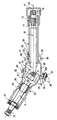
- This steering column comprises two sections of transmission control shaft, a first section 11 of which a grooved end 12 is adapted to receive a flywheel (not shown) and a second section 13 also comprising a grooved end 14 on which is engaged a adapter part 15, in the form of a socket, allowing the connection of the end 14 to the inlet of the steering box, which can in particular be constituted by the inlet axis of a power steering valve.
- the sleeve 15 has for this purpose internal grooves 17 and is split axially in the vicinity of these grooves to provide an annular clamping flange 18.
- the sections 11 and 13 are connected end to end by an articulated coupling means constituted here by a seal.
- each fork 21, 22 of the universal joint 20 constituting an axial end of one of the sections 11, 13 respectively.
- the steering column further comprises two sleeves 23 and 24, forming a housing and respectively housing the sections 11 and 13.
- each sleeve 23 or 24 has a generally cylindrical shape but its extreme portion 25 or 26 housing the fork 21 or 22, respectively, has a section widened accordingly so as not to risk blocking the universal joint 20.
- the section 11 is mounted in rotation about its longitudinal axis in the sleeve 23 by means of a ball bearing 27 on the one hand, located at the end of the sleeve 23 which is opposite to the enlarged end portion 25 and to an internal bearing 28 on the other hand, provided in particular with a contact lining 29 made of rubber.
- the sleeves 23 and 24 are assembled end to end (by their enlarged end portions 25 and 26) and for this purpose comprise two cooperating means forming assembly flanges 30 and 31, respectively, at least one of which is inclined relative to the normal of the longitudinal axis of the sleeve to which it belongs.
- the two flanges 30 and 31 are inclined in this way, that is to say that the flange 30 is slightly inclined relative to a plane perpendicular to the longitudinal axis 32 of the sleeve 23 while the flange 31 is slightly inclined relative to a plane perpendicular to the longitudinal axis 33 of the sleeve 24.
- the means forming flanges 30 and 31 are shaped with flat assembly surfaces 45 and 46, respectively, in mutual contact after assembly of the sleeves and thus defining an assembly plane of these, in which center O of the universal joint 20 is substantially located.
- means of assembly and tightening 35 of these flanges 30 and 31 are operative for at least two relative angular positions of the sleeves 23 and 24.
- these means of assembly and tightening consist of three bolts 36 mounted on the periphery of the flange 30 (three bolts are provided spaced at 120 ° at the periphery of this flange but only one is visible in the drawing) and the nut 37 of each bolt is arranged in shape lug capable of coming into engagement, when tightening, with a peripheral shoulder 37a of the flange 31.
- the external perimeter of the two assembly surfaces 45 and 46 is circular so that one can thus obtain an infinity of relative angular positions between the two sleeves 23 and 24, a given angular position being stabilized by the tightening of the bolts 36.
- the sleeve 24 mainly comprises two parts 38 and 39 fitted coaxially one inside the other.
- Part 38 is made up of substantially all of the aforementioned enlarged end portion 26 and the flange 31 and it has an internal bore 40 which receives the cylindrical end of part 39.
- the wall 41 of bore 40 has an axial slot 42 over a certain length, to transform this wall 41 into a sort of annular clamping flange; the slot 42 being closed by means of a bolt 43.
- the part 38 is orientable coaxially with respect to the part 39 (by momentary loosening of the bolt 43) which is fixed relative to a support frame (not shown ) on which the other elements of the vehicle's steering system are mounted.
- the adjustment of the steering wheel tilt is therefore as follows.
- the bolts 36 being loosened, it is possible to slide the two contact surfaces 45 and 46 in rotation relative to each other.
- This sliding is obviously accompanied by a variation in the angle between the axes 32 and 33, that is to say in fact a variation in the inclination of the flywheel which is mounted at the grooved end 12 of the section. 11.
Landscapes
- Engineering & Computer Science (AREA)
- Chemical & Material Sciences (AREA)
- Combustion & Propulsion (AREA)
- Transportation (AREA)
- Mechanical Engineering (AREA)
- Steering Controls (AREA)
Description
- L'invention concerne une colonne de direction pour véhicule automobile à inclinaison réglable permettant de positionner et d'orienter le volant selon le souhait du conducteur habituel du véhicule.
- On a déjà proposé des systèmes permettant de modifier l'orientation du volant d'un véhicule automobile, pour un plus grand confort de conduite de l'utilisateur. Jusqu'à présent, on a surtout rencontré de tels systèmes sur certains véhicules de tourisme. Particulièrement, on connaît un système consistant en une articulation blocable disposée entre le volant et l'extrémité de l'arbre de commande de transmission, un levier disposé sur le côté du volant permettant de faire jouer l'articulation blocable et de l'immobiliser dans une position voulue. Un tel système est relativement compliqué et d'un prix de revient élevé.
- Le brevet français 1 410 866 décrit par ailleurs une colonne de direction réglable comportant deux tronçons d'arbre de commande connectés bout à bout par un moyen de couplage articulé, et deux manchons abritant respectivement ces tronçons d'arbre et assemblés bout à bout grâce à des moyens coopérants. Toutefois, dans ce document, les deux manchons sont reliés l'un à l'autre de façon articulée par des tourillons, la position angulaire relative des manchons étant déterminée par une biellette articulée sur l'un des manchons et couplée à un moteur électrique de réglage de position disposé sur l'autre manchon. Un tel système est également relativement compliqué, délicat, et d'un prix de revient élevé.
- L'invention a pour objet de proposer un système plus simple, robuste et plus fiable, bien adapté pour équiper un véhicule poids lourd qui représente le domaine d'application principalement visé.
- Dans cet esprit, l'invention concerne donc une colonne de direction pour véhicule automobile, du type comportant deux tronçons d'arbre de commande connectés bout à bout par un moyen de couplage articulé et deux manchons abritant respectivement lesdits tronçons et assemblés bout à bout grâce à deux moyens coopérants, caractérisée en ce que les moyens coopérants des manchons forment brides d'assemblage, dont l'un au moins des plans est incliné par rapport à la normale de l'axe longitudinal du manchon auquel il appartient, et en ce que des moyens d'assemblage et de serrage desdits moyens coopérants formant brides sont opérants pour au moins deux positions angulaires relatives desdits manchons.
- Un mode de réalisation préféré d'une colonne de direction conforme à l'invention permet un réglage relatif des deux parties de la colonne de direction en une infinité de positions angulaires possibles.
- L'invention sera mieux comprise et d'autres avantages de celle-ci apparaîtront mieux à la lumière de la description qui va suivre d'un mode de réalisation préféré de l'invention et faite en référence au dessin annexé dans lequel la figure unique représente une vue en coupe d'une colonne de direction conforme aux principes de l'invention.
- Cette colonne de direction comporte deux tronçons d'arbre de commande de transmission, un premier tronçon 11 dont une extrémité cannelée 12 est adaptée pour recevoir un volant (non représenté) et un second tronçon 13 comportant également une extrémité cannelée 14 sur laquelle est engagée une pièce d'adaptation 15, en forme de douille, permettant la connexion de l'extrémité 14 à l'entrée du boîtier de direction, laquelle peut notamment être constituée par l'axe d'entrée d'une valve de servo-direction. La douille 15 comporte à cet effet des cannelures internes 17 et est fendue axialement au voisinage de ces cannelures pour ménager une bride annulaire de serrage 18. Les tronçons 11 et 13 sont connectés bout à bout par un moyen de couplage articulé constitué ici par un joint homocinétique et de préférence universel d'articulation à la Cardan 20, chaque fourche 21, 22 du joint universel 20 constituant une extrémité axiale de l'un des tronçons 11, 13 respectivement. La colonne de direction comporte en outre deux manchons 23 et 24, formant un boîtier et abritant respectivement les tronçons 11 et 13. Pour cela, chaque manchon 23 ou 24 a une forme générale cylindrique mais sa portion extrême 25 ou 26 abritant la fourche 21 ou 22, respectivement, a une section élargie en conséquence pour ne pas risquer de bloquer le joint universel 20. Le tronçon 11 est monté en rotation autour de son axe longitudinal dans le manchon 23 grâce à un roulement à billes 27 d'une part, situé à l'extrémité du manchon 23 qui est opposée à la portion extrême élargie 25 et à un palier interne 28 d'autre part, muni notamment d'une garniture de contact 29 en caoutchouc.
- Selon l'invention, les manchons 23 et 24 sont assemblés bout à bout (par leurs portions extrêmes élargies 25 et 26) et comportent pour cela deux moyens coopérants formant brides d'assemblage 30 et 31, respectivement, dont l'un au moins est incliné par rapport à la normale de l'axe longitudinal du manchon auquel il appartient. Dans l'exemple décrit, les deux brides 30 et 31 sont inclinées de cette façon, c'est-à-dire que la bride 30 est légèrement inclinée par rapport à un plan perpendiculaire à l'axe longitudinal 32 du manchon 23 tandis que la bride 31 est légèrement inclinée par rapport à un plan perpendiculaire à l'axe longitudinal 33 du manchon 24.
- Selon le mode de réalisation représenté, les moyens formant brides 30 et 31 sont conformés avec des surfaces planes d'assemblage 45 et 46, respectivement, en contact mutuel après assemblage des manchons et définissant ainsi un plan d'assemblage de ceux-ci, dans lequel le centre O du joint universel 20 est sensiblement situé. D'autre part, des moyens d'assemblage et de serrage 35 de ces brides 30 et 31 sont opérants pour au moins deux positions angulaires relatives des manchons 23 et 24. Dans le présent mode de réalisation, ces moyens d'assemblage et de serrage sont constitués par trois boulons 36 montés à la périphérie de la bride 30 (trois boulons sont prévus espacés à 120° à la périphérie de cette bride mais un seul est visible sur le dessin) et l'écrou 37 de chaque boulon est agencé en forme d'ergot susceptible de venir en engagement, au serrage, avec un épaulement périphérique 37a de la bride 31. De préférence, le périmètre externe des deux surfaces d'assemblage 45 et 46 est circulaire de sorte qu'on peut ainsi obtenir une infinité de positions angulaires relatives entre les deux manchons 23 et 24, une position angulaire donnée étant stabilisée par le serrage des boulons 36. On notera à ce propos que le manchon 24 comporte principalement deux parties 38 et 39 emmanchées coaxialement l'une dans l'autre. La partie 38 se compose sensiblement de toute la portion extrême élargie 26 précitée et de la bride 31 et elle comporte un alésage interne 40 qui reçoit l'extrémité cylindrique de la partie 39. La paroi 41 de l'alésage 40 comporte une fente axiale 42 sur une certaine longueur, pour transformer cette paroi 41 en une sorte de bride annulaire de serrage ; la fente 42 étant refermée au moyen d'un boulon 43. De cette façon, la partie 38 est orientable coaxialement par rapport à la partie 39 (par desserrage momentané du boulon 43) laquelle est fixe par rapport à un châssis-support (non représenté) sur lequel sont montés les autres éléments du système de direction du véhicule.
- Le réglage de l'inclinaison du volant se fait donc de la façon suivante. Les boulons 36 étant desserrés, il est possible de faire glisser en rotation les deux surfaces de contact 45 et 46 l'une par rapport à l'autre. Ce glissement s'accompagne bien évidemment d'une variation de l'angle entre les axes 32 et 33, c'est-à-dire en fait une variation de l'inclinaison du volant qui est monté à l'extrémité cannelée 12 du tronçon 11. Il suffit de resserrer les boulons 36 lorsque l'inclinaison du volant correspond au souhait du conducteur du véhicule. Etant donné que cette variation d'inclinaison du volant s'accompagne d'un déport latéral de celui-ci, il suffit de desserrer momentanément le boulon 43 et de faire tourner axialement la partie 38 par rapport à la partie fixe 39 pour compenser ce déport et ramener le volant en bonne position.
Claims (6)
Applications Claiming Priority (2)
| Application Number | Priority Date | Filing Date | Title |
|---|---|---|---|
| ES489058 | 1980-02-07 | ||
| ES489058A ES489058A0 (es) | 1980-02-07 | 1980-02-07 | Columna de direccion para vehiculos automoviles |
Publications (2)
| Publication Number | Publication Date |
|---|---|
| EP0034099A1 EP0034099A1 (fr) | 1981-08-19 |
| EP0034099B1 true EP0034099B1 (fr) | 1983-07-13 |
Family
ID=8479919
Family Applications (1)
| Application Number | Title | Priority Date | Filing Date |
|---|---|---|---|
| EP81400187A Expired EP0034099B1 (fr) | 1980-02-07 | 1981-02-06 | Colonne de direction pour véhicule automobile |
Country Status (8)
| Country | Link |
|---|---|
| US (1) | US4430905A (fr) |
| EP (1) | EP0034099B1 (fr) |
| JP (1) | JPS56149258A (fr) |
| AR (1) | AR223092A1 (fr) |
| AU (1) | AU6677181A (fr) |
| BR (1) | BR8100673A (fr) |
| DE (1) | DE3160576D1 (fr) |
| ES (1) | ES489058A0 (fr) |
Families Citing this family (10)
| Publication number | Priority date | Publication date | Assignee | Title |
|---|---|---|---|---|
| US5136894B1 (en) * | 1990-08-31 | 1996-10-15 | Bankers Trust Co | Tiltable marine steering helm |
| US5090730A (en) * | 1991-01-23 | 1992-02-25 | Itt Corporation | Vehicle steering column apparatus |
| US5470264A (en) * | 1994-11-15 | 1995-11-28 | Brunswick Corporation | Marine drive shift shaft mounting system |
| GB9523901D0 (en) * | 1995-11-22 | 1996-01-24 | Astec Dev Ltd | Bend and orientation apparatus |
| TW364409U (en) * | 1997-08-11 | 1999-07-11 | Work Tools Inc | A double universal joint angle driving assembly |
| US6263749B1 (en) * | 1999-11-08 | 2001-07-24 | Muncie Power Products, Inc. | Power take-off extended shaft |
| US6499548B2 (en) | 1999-11-08 | 2002-12-31 | Muncie Power Products, Inc. | Power take-off extended shaft |
| DE102010041960B4 (de) * | 2010-07-30 | 2012-12-20 | Aktiebolaget Skf | Gelenkanordnung |
| JP2017145887A (ja) * | 2016-02-17 | 2017-08-24 | 株式会社ジェイテクト | ステアリング装置の連結装置 |
| ITUB20161042A1 (it) * | 2016-02-25 | 2017-08-25 | C O B O S P A | Telaio di supporto per piantone di sterzo per trattori e sistemi associati ad esso |
Citations (1)
| Publication number | Priority date | Publication date | Assignee | Title |
|---|---|---|---|---|
| FR1410866A (fr) * | 1963-11-06 | 1965-09-10 | Gen Motors Corp | Colonne de direction réglable pour véhicule automobile |
Family Cites Families (6)
| Publication number | Priority date | Publication date | Assignee | Title |
|---|---|---|---|---|
| US327877A (en) * | 1885-10-06 | Universal angle coupling and union | ||
| US1478216A (en) * | 1921-05-23 | 1923-12-18 | Gilbody Fred Hampson | Bracket for pulleys, levers, or the like |
| US2559093A (en) * | 1949-05-09 | 1951-07-03 | Alfred H Rzeppa | Torque transmitting angle coupling |
| US3144785A (en) * | 1962-09-21 | 1964-08-18 | Steiner George | Adjustable steering column |
| GB1153225A (en) * | 1967-01-18 | 1969-05-29 | Borg Warner | Steering Column |
| US3934488A (en) * | 1975-03-21 | 1976-01-27 | Rockwell International Corporation | Steering control head with adjustable positioning means |
-
1980
- 1980-02-07 ES ES489058A patent/ES489058A0/es active Granted
-
1981
- 1981-01-30 AU AU66771/81A patent/AU6677181A/en not_active Abandoned
- 1981-02-02 AR AR284184A patent/AR223092A1/es active
- 1981-02-05 BR BR8100673A patent/BR8100673A/pt not_active IP Right Cessation
- 1981-02-06 DE DE8181400187T patent/DE3160576D1/de not_active Expired
- 1981-02-06 EP EP81400187A patent/EP0034099B1/fr not_active Expired
- 1981-02-06 JP JP1587681A patent/JPS56149258A/ja active Pending
- 1981-02-09 US US06/232,616 patent/US4430905A/en not_active Expired - Lifetime
Patent Citations (1)
| Publication number | Priority date | Publication date | Assignee | Title |
|---|---|---|---|---|
| FR1410866A (fr) * | 1963-11-06 | 1965-09-10 | Gen Motors Corp | Colonne de direction réglable pour véhicule automobile |
Also Published As
| Publication number | Publication date |
|---|---|
| ES8100991A1 (es) | 1980-12-01 |
| EP0034099A1 (fr) | 1981-08-19 |
| AR223092A1 (es) | 1981-07-15 |
| ES489058A0 (es) | 1980-12-01 |
| AU6677181A (en) | 1981-08-13 |
| US4430905A (en) | 1984-02-14 |
| JPS56149258A (en) | 1981-11-19 |
| DE3160576D1 (en) | 1983-08-18 |
| BR8100673A (pt) | 1981-08-18 |
Similar Documents
| Publication | Publication Date | Title |
|---|---|---|
| EP0104108B1 (fr) | Dispositif de bras support d'une roue motrice | |
| FR2632581A1 (fr) | ||
| FR2569145A1 (fr) | Arbre de transmission pour vehicule automobile | |
| FR2613448A1 (fr) | Mecanisme a engrenages a axes perpendiculaires | |
| EP0673813B1 (fr) | Essuie-glace de véhicule automobile, comportant des moyens d'orientation de la tête d'entraínement | |
| CA2090937A1 (fr) | Ensemble de colonne de direction reglable en position pour vehicule automobile | |
| EP0034099A1 (fr) | Colonne de direction pour véhicule automobile | |
| WO2020193585A1 (fr) | Trottinette motorisée avec transmission par système à engrenage | |
| FR2560565A1 (fr) | Suspension a roues independantes a bras posterieurs diagonaux pour vehicule a moteur | |
| EP1544489B1 (fr) | Mâchoire de cardan démontable d'une colonne de direction de véhicule automobile | |
| FR2560568A1 (fr) | Retroviseur de vehicule orientable en deux plans par un mecanisme de commande a moteur electrique notamment | |
| FR2723887A1 (fr) | Suspension d'une roue directrice de vehicule | |
| FR2559108A1 (fr) | Dispositif de reglage de l'orientation et de l'inclinaison d'un projecteur pour vehicules automobiles | |
| FR2837773A1 (fr) | Appareil de direction du vehicule | |
| FR2690403A1 (fr) | Ensemble de colonne de direction réglable en position pour véhicule automobile. | |
| FR2912368A1 (fr) | Ensemble moteur et engrenage reducteur | |
| EP0559570A1 (fr) | Accouplement élastique | |
| EP1169210A1 (fr) | Vehicule a pendularite variable guidee | |
| FR2528790A1 (fr) | Mecanisme de suspension de roue de vehicule avec adaptation a la charge | |
| FR2715906A1 (fr) | Dispositif de fixation d'un organe sur un arbre de direction notamment de véhicule automobile. | |
| FR2782965A1 (fr) | Dispositif modulaire de correction de l'orientation d'un reflecteur de projecteur de vehicule automobile | |
| FR2553721A1 (fr) | Ensemble pour la transformation d'un vehicule a roues avant motrices en un vehicule a quatre roues motrices | |
| FR2712553A1 (fr) | Dispositif de limitation du braquage d'une roue directrice de véhicule. | |
| FR3144807A1 (fr) | Ensemble de tringlerie pour diriger des roues d'un véhicule automobile | |
| FR3155802A1 (fr) | Essieu pendulaire pour véhicule de type tricycle |
Legal Events
| Date | Code | Title | Description |
|---|---|---|---|
| PUAI | Public reference made under article 153(3) epc to a published international application that has entered the european phase |
Free format text: ORIGINAL CODE: 0009012 |
|
| 17P | Request for examination filed |
Effective date: 19810216 |
|
| AK | Designated contracting states |
Designated state(s): DE FR GB IT SE |
|
| ITF | It: translation for a ep patent filed | ||
| GRAA | (expected) grant |
Free format text: ORIGINAL CODE: 0009210 |
|
| AK | Designated contracting states |
Designated state(s): DE FR GB IT SE |
|
| REF | Corresponds to: |
Ref document number: 3160576 Country of ref document: DE Date of ref document: 19830818 |
|
| PLBE | No opposition filed within time limit |
Free format text: ORIGINAL CODE: 0009261 |
|
| STAA | Information on the status of an ep patent application or granted ep patent |
Free format text: STATUS: NO OPPOSITION FILED WITHIN TIME LIMIT |
|
| 26N | No opposition filed | ||
| ITTA | It: last paid annual fee | ||
| PGFP | Annual fee paid to national office [announced via postgrant information from national office to epo] |
Ref country code: GB Payment date: 19950127 Year of fee payment: 15 |
|
| EAL | Se: european patent in force in sweden |
Ref document number: 81400187.1 |
|
| PGFP | Annual fee paid to national office [announced via postgrant information from national office to epo] |
Ref country code: DE Payment date: 19950209 Year of fee payment: 15 |
|
| PGFP | Annual fee paid to national office [announced via postgrant information from national office to epo] |
Ref country code: SE Payment date: 19950215 Year of fee payment: 15 |
|
| PGFP | Annual fee paid to national office [announced via postgrant information from national office to epo] |
Ref country code: FR Payment date: 19950221 Year of fee payment: 15 |
|
| PG25 | Lapsed in a contracting state [announced via postgrant information from national office to epo] |
Ref country code: GB Effective date: 19960206 |
|
| PG25 | Lapsed in a contracting state [announced via postgrant information from national office to epo] |
Ref country code: SE Effective date: 19960207 |
|
| GBPC | Gb: european patent ceased through non-payment of renewal fee |
Effective date: 19960206 |
|
| PG25 | Lapsed in a contracting state [announced via postgrant information from national office to epo] |
Ref country code: FR Effective date: 19961031 |
|
| PG25 | Lapsed in a contracting state [announced via postgrant information from national office to epo] |
Ref country code: DE Effective date: 19961101 |
|
| REG | Reference to a national code |
Ref country code: FR Ref legal event code: ST |