EP0034218A1 - Projektor für Filme, Diapositive oder dergl. - Google Patents
Projektor für Filme, Diapositive oder dergl. Download PDFInfo
- Publication number
- EP0034218A1 EP0034218A1 EP80107958A EP80107958A EP0034218A1 EP 0034218 A1 EP0034218 A1 EP 0034218A1 EP 80107958 A EP80107958 A EP 80107958A EP 80107958 A EP80107958 A EP 80107958A EP 0034218 A1 EP0034218 A1 EP 0034218A1
- Authority
- EP
- European Patent Office
- Prior art keywords
- projector
- projector according
- hood
- closed
- base
- Prior art date
- Legal status (The legal status is an assumption and is not a legal conclusion. Google has not performed a legal analysis and makes no representation as to the accuracy of the status listed.)
- Granted
Links
Images

Classifications
-
- G—PHYSICS
- G03—PHOTOGRAPHY; CINEMATOGRAPHY; ANALOGOUS TECHNIQUES USING WAVES OTHER THAN OPTICAL WAVES; ELECTROGRAPHY; HOLOGRAPHY
- G03B—APPARATUS OR ARRANGEMENTS FOR TAKING PHOTOGRAPHS OR FOR PROJECTING OR VIEWING THEM; APPARATUS OR ARRANGEMENTS EMPLOYING ANALOGOUS TECHNIQUES USING WAVES OTHER THAN OPTICAL WAVES; ACCESSORIES THEREFOR
- G03B23/00—Devices for changing pictures in viewing apparatus or projectors
-
- G—PHYSICS
- G03—PHOTOGRAPHY; CINEMATOGRAPHY; ANALOGOUS TECHNIQUES USING WAVES OTHER THAN OPTICAL WAVES; ELECTROGRAPHY; HOLOGRAPHY
- G03B—APPARATUS OR ARRANGEMENTS FOR TAKING PHOTOGRAPHS OR FOR PROJECTING OR VIEWING THEM; APPARATUS OR ARRANGEMENTS EMPLOYING ANALOGOUS TECHNIQUES USING WAVES OTHER THAN OPTICAL WAVES; ACCESSORIES THEREFOR
- G03B21/00—Projectors or projection-type viewers; Accessories therefor
- G03B21/001—Slide projectors
Definitions
- the invention relates to a projector for films, slides or the like.
- a base which supports the projector and with a hood which can be slipped over the projector and which can be connected to the base to form a closed suitcase.
- the base consists of a plate with holders for the projector and with hooks, projections or the like, which engage in the closure parts of the hood.
- the projector is a unit that includes all the parts required for its operation, such as energy supply, light source, optics, etc., and can also be operated separately from the base.
- Such projectors are usually quite heavy.
- the invention has for its object to provide a projector that is ready for use by removing the hood, so it does not have to be lifted out of a suitcase and has such a small weight that it can be operated with base frames of a lightweight design and without exerting great forces on it desired height can be set.
- This object is achieved by the invention characterized in claim 1. Developments of the invention are described in the subclaims. By using a continuous or stepless film drive also for slide playback, additional undesirable forces are avoided that act transversely on the base.
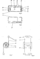
- the projector 1 shows a projector 1 packed for transport with a lower part 2 and a hood 3, which is put over the projector 1 and is detachably fastened to the upper side 4 of the lower part 2.
- the projector 1 contains the light source and optics as well as the facilities necessary for film or slide movement and adjustment.
- the energy supply 2a and the exchangeable control devices 2b for film movement and focus adjustment are arranged in the lower part 2 .
- the height of the projector 1 is arranged in the base 2.
- the projector 1 is mounted directly or via a cover plate 5 on a telescopic leg 6, which is fastened in the base 2.
- the cover plate 5 can also can be supplemented or replaced by designing the telescopic upper part 7. Control and power cables can be arranged within the telescopic leg 6.
- the height can be adjusted manually or remotely.
- a space is provided between the base 1 and the optics 8 of the projector 1, which can be used for accommodating, for example, a cable such as the network cord.
- the base 1 is set back in height and thereby has a container 10 for receiving a connecting cable 11.
- the connecting cable 11 is preferably self-rolling and thus always adapts to the height of the projector 1 relative to the lower part 2. It is designed as a flat cable bifilar.
- a space 9 is provided for accommodating the power switch 12, the fuse 13 and other setting means 14.
- the lower part 2 is provided with openings 15, 16 for receiving the mains plug or remote control plug. In the packaged state, these openings are covered by a carrying and connecting strap 17.
- Hood 3 and base 2 are designed so that together they form a closed case that envelops the projector 1 and the interior of the base.
- the hood 3 can be provided with a suitcase handle.
- the projector 1 is provided on both sides with sensor switches 18 for the film inlet drive, which switch on clockwise or counterclockwise rotation, depending on whether the cassette containing the film is attached to the right or left receptacle 19.
- a recessed grip 20 is provided, which is to facilitate the manual pulling out of the projector.
- This trough 20 can also have vertical ventilation bores.
- FIG. 2 shows the projector 1 in the operating position with the projector 1 raised.
- the bifilarly wound flat web cable 11 is rolled up in FIG. 1 and shown unrolled in FIG. 2.
- variable-length cable of a suitable design can also be provided within the telescope 6.
- the projector 1, raised in accordance with FIG. 2 can be rotated by hand or by motor around the axis of the telescope. Both the telescope and the cable 11 or a cable located in the telescope allow such a rotation without additional constructions. With motorized adjustment, the additional effort can be kept relatively low.
- buttons 21 interacting with the fastening buttons 22 are clearly visible, as is a recess on the bottom of the lower part 2 for fixing the belt 17 in position.
- FIG. 5 shows a plan view of the lower part 2.
- the telescope 6 and spaces 24 for cassette boxes (these are containers for cassettes described in P 21 55 521 for uncut films) 25 for one or more Lerr cassettes and 26 for a remote control (not shown) are clearly visible.
- FIG. 6 shows a view from below of the hood 3 with a space 27 for a mains cable.
- 7 and 8 show in two side views the rolled-up cable 11 with plugs 28 and lateral guides 29 and strips 30 and 31 which comprise the central part of the undivided cable 11 between the plug core so that the cable 11 relaxes itself around the strips rolls up like a spring.
- the edge of the parts 29 corresponds approximately to the cable width.
Landscapes
- Physics & Mathematics (AREA)
- General Physics & Mathematics (AREA)
- Projection Apparatus (AREA)
Abstract
Description
- Die Erfindung betrifft einen Projektor für Filme, Diapositive oder dgl. mit einem den Projektor tragenden Sockel und mit einer über den Projektor stülpbaren Haube, die mit dem Sockel zu einem geschlossenen Koffer verbindbar ist. Bei bekannten Projektoren dieser Bauart besteht der Sockel aus einer Platte mit Halterungen für den Projektor und mit Haken, Vorsprüngen oder dgl., in die Verschlußteile der Haube eingreifen. Der Projektor ist eine Baueinheit, die alle für ihren Betrieb erforderlichen Teile wie Energieversorgung, Lichtquelle, Optik etc. einschließt und auch gesondert vom Sockel betrieben werden kann. Solche Projektoren sind meist recht schwer. Es ist auch bekannt, Dia-Projektoren mit Magazinen zu versehen und die Dias nacheinander fernsteuerbar zu projizieren und dabei die Schärfe zu variieren. Solche Projektoren sind umfangreich und werden meist in gesonderte Koffer eingesetzt. Sie werden zur Vorführung auf Spezialtische gesetzt. Höhenverstellungen des Bildes erfolgen meist durch Verstellen der Winkellage des Projektors und bewirken dadurch Trapezfehler.
- Der Erfindung liegt die Aufgabe zugrunde, einen Projektor zu schaffen, der durch Abnahme der Haube betriebsbereit ist, also nicht aus einem Koffer herausgehoben werden muß und der ein so kleines Gewicht hat, daß er mit Untergestellen leichter Bauart betrieben und ohne Aufwendung großer Kräfte auf die erwünschte Höhe gestellt werden kann. Diese Aufgabe wird durch die im Anspruch 1 gekennzeichnete Erfindung gelöst. Weiterbildungen der Erfindung sind in den Unteransprüchen beschrieben. Durch die Verwendung eines köntinuierlichen bzw. stufenlosen Filmantriebs auch für die Dia-Wiedergabe werden zusätzliche unerwünschte Kräfte vermieden, die quer auf die Unterlage einwirken.
- Zur näheren Erläuterung der Erfindung wird im folgenden ein Ausführungsbeispiel an Hand der Zeichnung beschrieben. Diese zeigt in
- Fig. 1 den Längsschnitt eines Projektors
- Fig. 2 den Projektor gemäß Fig 1 in Betriebsstellung
- Fig. 3 - 9 Teilansichten.
- In Fig. 1 ist ein für den Transport verpackter Projektor 1 mit einem Unterteil 2 und einer Haube 3 dargestellt, die über den Projektor 1 gestülpt und an der Oberseite 4 des Unterteils 2 lösbar befestigt ist. Der Projektor 1 enthält Lichtquelle und Optik sowie die zur Film- bzw. Dia-Bewegung und Einstellung notwendigen Einrichtungen. Im Unterteil 2 sind die Energieversorgung 2a und die auswechselbaren Steuereinrichtungen 2b für Filmbewegung und Schärfeeinstellung angeordnet. Der Projektor 1 ist höhenverstellbar im Sockel 2 angeordnet. Zu diesem Zweck ist der Projektor 1 direkt oder über eine Deckplatte 5 auf einem Teleskopbein 6 gelagert, das im Sockel 2 befestigt ist. Die Deckplatte 5 kann auch durch Ausbildung des Teleskop-Oberteils 7 ergänzt oder ersetzt werden. Innerhalb des Teleskopbeins 6 können Steuer-und Stromkabel angeordnet sein. Die Höhenverstellbarkeit ist manuell oder fernsteuerbar möglich. Zwischen dem Sockel 1 und der Optik 8 des Projektors 1 ist ein Raum vorgesehen, der für die Unterbringung z.B. eines Kabels wie der Netzschnur ausgenutzt werden kann. Unterhalb der Deckplatte 5 ist der Sockel 1 in seiner Höhe zurückgesetzt und weist dadurch einen Behälter 10 für die Aufnahme eines Verbindungskabels 11 auf. Das Verbindungskabel 11 ist vorzugsweise selbstaufrollend ausgebildet-und paßt sich so stets der Höhenlage des Projektors 1 relativ zum Unterteil 2 an. Es ist als Flachbahnkabel bifilar ausgebildet. An der Vorderseite des Unterteils 2 ist ein Raum 9 für die Unterbringung des Netzschalters 12, der Sicherung 13 sowie weiterer Einstellmittel 14 vorgesehen. Das Unterteil 2 ist mit Öffnungen 15,16 für die Aufnahme von Netzstecker bzw. Fernbedienungsstecker versehen. Im verpackten Zustand sind diese Öffnungen durch einen Trag- und Verbindungsriemen 17 verdeckt. Haube 3 und Sockel 2 sind so ausgebildet, daß sie zusammen einen geschlossenen, den Projektor 1 und den Sockelinnenraum umhüllenden Koffer bilden. Die Haube 3 kann mit einem Koffergriff versehen werden. Der Projektor 1 ist an seinem vorderen Ende beidseitig mit Sensorschaltern 18 für den Filmeinlaufantrieb versehen, die Rechts- oder Linkslauf einschalten, je nachdem, ob die den Film enthaltende Kassette an der rechten oder linken Aufnahme 19 angesetzt wird. Im hinteren Teil des Projektors 1 ist eine Griffmulde 20 vorgesehen, die das manuelle Ausziehen des Projektors erleichtern soll. Diese Mulde 20 kann zugleich vertikale Entlüftungsbohrungen aufweisen.
- Fig. 2 zeigt den Projektor 1 in Betriebsstellung mit hochgefahrenem Projektor 1. Das bifilar aufgewickelte Flachbahnkabel 11 ist in Fig. 1 aufgerollt und in Fig. 2 entrollt dargestellt.
- Statt eines solchen Flachbahnkabels 11 kann auch innerhalb des Teleskops 6 ein längenveränderliches Kabel geeigneter Bauart vorgesehen werden.
- Der gemäß Fig 2 hochgefahrene Projektor 1 kann von Hand oder motorisch um die Achse des Teleskops gedreht werden. Sowohl das Teleskop als auch das Kabel 11 oder ein im Teleskop an - geotdnetes Kabel lassen eine solche Drehung ohne zusätzliche Konstruktionen zu. Bei motorischer Verstellung kann der zusätzliche Aufwand relativ gering gehalten werden.
- Fig 3 zeigt den Riemen 17 mit Befestigungsknöpfen 22, die mit entsprechenden Knöpfen von Unterteil 2-und Haube 3 zusammenwirken. Der Riemen 17 wird während des Betriebes des Projektors ganz abgenommen.
- Fig.4 zeigt die Ausbildung des geschlossenen Koffer-s 2,3 ohne Riemen 17. Bei dieser Abbildung sind die mit den Be - festigungsknöpfen 22 zusammenwirkenden Knöpfe 21 deutlich sichtbar wie auch eine Aussparung am Boden des Unterteils 2 für die Lagefixierung des Riemens 17.
- Fig.5 zeigt eine Draufsicht auf das Unterteil 2 . Deutlich sichtbar sind das Teleskop 6 sowie Räume 24 für Kassettenboxen (das sind Behälter für in P 21 55 521 beschriebene Kassetten für unzerschnittene Filme) 25 für ein oder mehrere Lerrkassetten und 26 für eine nicht gezeigte Fernbedienung.
- Fig 6 zeigt einen Blick von unten auf die Haube 3 mit einem Raum 27 für ein Netzkabel. Fig 7 und 8 zeigen in zwei Seitenansichten das aufgerollte Kabel 11 mit Steckern 28 und seitlichen Führungen 29 sowie Leisten 30 und 31, die das Mittelteil des zwischen den Stekkern ungeteilten Kabels 11 so umfassen, daß sich das Kabel 11 bei Entspannung von selbst um die Leisten federartig aufrollt. Der Abszand der Teile 29 entspricht etwa der Kabelbreite.
Claims (12)
Applications Claiming Priority (2)
| Application Number | Priority Date | Filing Date | Title |
|---|---|---|---|
| DE19792950889 DE2950889A1 (de) | 1979-12-18 | 1979-12-18 | Projektor fuer filme, diapositive o.dgl. |
| DE2950889 | 1979-12-18 |
Publications (2)
| Publication Number | Publication Date |
|---|---|
| EP0034218A1 true EP0034218A1 (de) | 1981-08-26 |
| EP0034218B1 EP0034218B1 (de) | 1986-12-30 |
Family
ID=6088810
Family Applications (1)
| Application Number | Title | Priority Date | Filing Date |
|---|---|---|---|
| EP80107958A Expired EP0034218B1 (de) | 1979-12-18 | 1980-12-17 | Projektor für Filme, Diapositive oder dergl. |
Country Status (5)
| Country | Link |
|---|---|
| EP (1) | EP0034218B1 (de) |
| JP (1) | JPS5697338A (de) |
| DE (1) | DE2950889A1 (de) |
| ES (1) | ES8202964A1 (de) |
| WO (1) | WO1981001752A1 (de) |
Cited By (1)
| Publication number | Priority date | Publication date | Assignee | Title |
|---|---|---|---|---|
| GB2389726A (en) * | 2002-02-16 | 2003-12-17 | Alan Maddock | Projection apparatus adaptor |
Families Citing this family (4)
| Publication number | Priority date | Publication date | Assignee | Title |
|---|---|---|---|---|
| DE3824187A1 (de) * | 1988-07-16 | 1990-01-18 | Arnold & Richter Kg | Projektor |
| DE4124502A1 (de) * | 1991-07-24 | 1993-01-28 | Guido Dipl Ing Haehnel | Diaprojektions-bildwandler |
| DE9209310U1 (de) * | 1992-07-09 | 1992-11-19 | AV-Kommunikation Anders + Kern GmbH & Co KG, 2000 Norderstedt | Durchlichtprojektor |
| JP4941887B2 (ja) * | 2006-07-26 | 2012-05-30 | 東芝ホームテクノ株式会社 | 表示装置 |
Citations (1)
| Publication number | Priority date | Publication date | Assignee | Title |
|---|---|---|---|---|
| FR2041352A5 (de) * | 1969-04-22 | 1971-01-29 | Chemaille Sa |
Family Cites Families (9)
| Publication number | Priority date | Publication date | Assignee | Title |
|---|---|---|---|---|
| DE290138C (de) * | ||||
| GB271923A (en) * | 1926-01-28 | 1927-05-30 | John Edward Thornton | Improvements in or relating to kinematograph and optical projection apparatus |
| US2341223A (en) * | 1939-10-11 | 1944-02-08 | Lillie William | Advertising projection |
| CH218509A (de) * | 1941-06-06 | 1941-12-15 | Muriset Josy | Lampe. |
| US2492807A (en) * | 1946-03-15 | 1949-12-27 | Associated Photo Products Inc | Carrier case |
| US3049971A (en) * | 1959-11-25 | 1962-08-21 | Sylvania Electric Prod | Projector |
| GB892809A (en) * | 1959-12-30 | 1962-03-28 | Voigtlaender Ag | Case for optical projector |
| FR1373973A (fr) * | 1963-10-23 | 1964-10-02 | Pied télescopique portable support de projecteur cinématographique ou autre appareil à régulateur de tension secteur incorporé | |
| DE2607950A1 (de) * | 1976-02-27 | 1977-09-01 | Kabel Metallwerke Ghh | Vorrichtung zum selbsttaetigen aufwickeln einer elektrischen leitung auf eine trommel |
-
1979
- 1979-12-18 DE DE19792950889 patent/DE2950889A1/de active Granted
-
1980
- 1980-12-16 WO PCT/DE1980/000187 patent/WO1981001752A1/de not_active Ceased
- 1980-12-17 EP EP80107958A patent/EP0034218B1/de not_active Expired
- 1980-12-18 JP JP17815680A patent/JPS5697338A/ja active Pending
- 1980-12-19 ES ES497987A patent/ES8202964A1/es not_active Expired
Patent Citations (1)
| Publication number | Priority date | Publication date | Assignee | Title |
|---|---|---|---|---|
| FR2041352A5 (de) * | 1969-04-22 | 1971-01-29 | Chemaille Sa |
Cited By (2)
| Publication number | Priority date | Publication date | Assignee | Title |
|---|---|---|---|---|
| GB2389726A (en) * | 2002-02-16 | 2003-12-17 | Alan Maddock | Projection apparatus adaptor |
| GB2389726B (en) * | 2002-02-16 | 2004-09-08 | Alan Maddock | An adaptor for portable visual display permitting user attachment and configuration of accessories and media |
Also Published As
| Publication number | Publication date |
|---|---|
| JPS5697338A (en) | 1981-08-06 |
| ES497987A0 (es) | 1982-02-16 |
| ES8202964A1 (es) | 1982-02-16 |
| EP0034218B1 (de) | 1986-12-30 |
| DE2950889C2 (de) | 1990-05-23 |
| WO1981001752A1 (fr) | 1981-06-25 |
| DE2950889A1 (de) | 1981-06-25 |
Similar Documents
| Publication | Publication Date | Title |
|---|---|---|
| DE2251737A1 (de) | Zahnaerztlicher patientenstuhl mit parallelogrammtragarm | |
| DE3625944C2 (de) | ||
| EP0034218B1 (de) | Projektor für Filme, Diapositive oder dergl. | |
| DE3213317A1 (de) | Kamerahalterung | |
| CH383772A (de) | Kopiergerät zum Reproduzieren eines Bildes von einer Musterfolie auf eine Filmfolie | |
| DE2652069C3 (de) | Vorrichtung zum elektrographischen Herstellen einer Platte für den Offsetdruck | |
| DE8808688U1 (de) | Aus einem zusammengefalteten Aufbewahrungszustand in einen geöffneten Arbeitszustand überführbare Aufnahmevorrichtung für ein Diapositiv | |
| EP0635753A1 (de) | Vorrichtung zum Halten flexibler Bildwände, insbesondere Hintergrundwände | |
| DE8224767U1 (de) | Overhead-projektor | |
| DE3312859C1 (de) | Transportable Vorführeinheit mit einem Fernsehgerät und einem Video-Recorder | |
| DE4003432C1 (en) | Mobile unit for storing transparencies - has folding support with raisable or lowerable projection position and folding storing section | |
| DE1797554A1 (de) | Diaprojektor | |
| DE3216224C2 (de) | Epidiaskop | |
| DE3232639A1 (de) | Overhead-projektor | |
| DE806595C (de) | Bruststativ | |
| DE831354C (de) | Vergroesserungsgeraet | |
| DE379063C (de) | Schrank fuer Vorfuehrungskinematographen | |
| DE3113687C2 (de) | Titelgerät für Filme | |
| DE2624946B2 (de) | Projektionsgerät | |
| US4439028A (en) | Projector assembly | |
| DE614152C (de) | Zusammenlegbarer Sucher fuer photographische Apparate | |
| DE8227891U1 (de) | Stativwagen | |
| DE7737980U1 (de) | Bausatz zur projizierung von diapositiven oder filmen | |
| DE2619730A1 (de) | Plansichtgeraet | |
| DE731217C (de) | Bildwechselschieber fuer Stehbildwerfer |
Legal Events
| Date | Code | Title | Description |
|---|---|---|---|
| PUAI | Public reference made under article 153(3) epc to a published international application that has entered the european phase |
Free format text: ORIGINAL CODE: 0009012 |
|
| AK | Designated contracting states |
Designated state(s): CH FR GB IT |
|
| 17P | Request for examination filed |
Effective date: 19820423 |
|
| GRAA | (expected) grant |
Free format text: ORIGINAL CODE: 0009210 |
|
| AK | Designated contracting states |
Kind code of ref document: B1 Designated state(s): CH FR GB IT LI |
|
| ITF | It: translation for a ep patent filed | ||
| ET | Fr: translation filed | ||
| PLBE | No opposition filed within time limit |
Free format text: ORIGINAL CODE: 0009261 |
|
| 26N | No opposition filed | ||
| PG25 | Lapsed in a contracting state [announced via postgrant information from national office to epo] |
Ref country code: GB Effective date: 19881217 |
|
| PG25 | Lapsed in a contracting state [announced via postgrant information from national office to epo] |
Ref country code: CH Effective date: 19881231 Ref country code: LI Effective date: 19881231 |
|
| GBPC | Gb: european patent ceased through non-payment of renewal fee | ||
| PG25 | Lapsed in a contracting state [announced via postgrant information from national office to epo] |
Ref country code: FR Free format text: LAPSE BECAUSE OF NON-PAYMENT OF DUE FEES Effective date: 19890831 |
|
| REG | Reference to a national code |
Ref country code: CH Ref legal event code: PL |
|
| REG | Reference to a national code |
Ref country code: FR Ref legal event code: ST |