EP0034312B1 - Accouplement à action rapide accouplable aussi sous pression - Google Patents
Accouplement à action rapide accouplable aussi sous pression Download PDFInfo
- Publication number
- EP0034312B1 EP0034312B1 EP19810100845 EP81100845A EP0034312B1 EP 0034312 B1 EP0034312 B1 EP 0034312B1 EP 19810100845 EP19810100845 EP 19810100845 EP 81100845 A EP81100845 A EP 81100845A EP 0034312 B1 EP0034312 B1 EP 0034312B1
- Authority
- EP
- European Patent Office
- Prior art keywords
- coupling
- valve
- quick
- valve body
- locking ball
- Prior art date
- Legal status (The legal status is an assumption and is not a legal conclusion. Google has not performed a legal analysis and makes no representation as to the accuracy of the status listed.)
- Expired
Links
Images


Classifications
-
- F—MECHANICAL ENGINEERING; LIGHTING; HEATING; WEAPONS; BLASTING
- F16—ENGINEERING ELEMENTS AND UNITS; GENERAL MEASURES FOR PRODUCING AND MAINTAINING EFFECTIVE FUNCTIONING OF MACHINES OR INSTALLATIONS; THERMAL INSULATION IN GENERAL
- F16L—PIPES; JOINTS OR FITTINGS FOR PIPES; SUPPORTS FOR PIPES, CABLES OR PROTECTIVE TUBING; MEANS FOR THERMAL INSULATION IN GENERAL
- F16L37/00—Couplings of the quick-acting type
- F16L37/22—Couplings of the quick-acting type in which the connection is maintained by means of balls, rollers or helical springs under radial pressure between the parts
- F16L37/23—Couplings of the quick-acting type in which the connection is maintained by means of balls, rollers or helical springs under radial pressure between the parts by means of balls
-
- F—MECHANICAL ENGINEERING; LIGHTING; HEATING; WEAPONS; BLASTING
- F16—ENGINEERING ELEMENTS AND UNITS; GENERAL MEASURES FOR PRODUCING AND MAINTAINING EFFECTIVE FUNCTIONING OF MACHINES OR INSTALLATIONS; THERMAL INSULATION IN GENERAL
- F16L—PIPES; JOINTS OR FITTINGS FOR PIPES; SUPPORTS FOR PIPES, CABLES OR PROTECTIVE TUBING; MEANS FOR THERMAL INSULATION IN GENERAL
- F16L37/00—Couplings of the quick-acting type
- F16L37/28—Couplings of the quick-acting type with fluid cut-off means
- F16L37/30—Couplings of the quick-acting type with fluid cut-off means with fluid cut-off means in each of two pipe-end fittings
- F16L37/32—Couplings of the quick-acting type with fluid cut-off means with fluid cut-off means in each of two pipe-end fittings at least one of two lift valves being opened automatically when the coupling is applied
-
- Y—GENERAL TAGGING OF NEW TECHNOLOGICAL DEVELOPMENTS; GENERAL TAGGING OF CROSS-SECTIONAL TECHNOLOGIES SPANNING OVER SEVERAL SECTIONS OF THE IPC; TECHNICAL SUBJECTS COVERED BY FORMER USPC CROSS-REFERENCE ART COLLECTIONS [XRACs] AND DIGESTS
- Y10—TECHNICAL SUBJECTS COVERED BY FORMER USPC
- Y10T—TECHNICAL SUBJECTS COVERED BY FORMER US CLASSIFICATION
- Y10T137/00—Fluid handling
- Y10T137/8158—With indicator, register, recorder, alarm or inspection means
- Y10T137/8326—Fluid pressure responsive indicator, recorder or alarm
-
- Y—GENERAL TAGGING OF NEW TECHNOLOGICAL DEVELOPMENTS; GENERAL TAGGING OF CROSS-SECTIONAL TECHNOLOGIES SPANNING OVER SEVERAL SECTIONS OF THE IPC; TECHNICAL SUBJECTS COVERED BY FORMER USPC CROSS-REFERENCE ART COLLECTIONS [XRACs] AND DIGESTS
- Y10—TECHNICAL SUBJECTS COVERED BY FORMER USPC
- Y10T—TECHNICAL SUBJECTS COVERED BY FORMER US CLASSIFICATION
- Y10T137/00—Fluid handling
- Y10T137/8593—Systems
- Y10T137/87917—Flow path with serial valves and/or closures
- Y10T137/87925—Separable flow path section, valve or closure in each
- Y10T137/87965—Valve- or closure-operated by coupling motion
-
- Y—GENERAL TAGGING OF NEW TECHNOLOGICAL DEVELOPMENTS; GENERAL TAGGING OF CROSS-SECTIONAL TECHNOLOGIES SPANNING OVER SEVERAL SECTIONS OF THE IPC; TECHNICAL SUBJECTS COVERED BY FORMER USPC CROSS-REFERENCE ART COLLECTIONS [XRACs] AND DIGESTS
- Y10—TECHNICAL SUBJECTS COVERED BY FORMER USPC
- Y10T—TECHNICAL SUBJECTS COVERED BY FORMER US CLASSIFICATION
- Y10T137/00—Fluid handling
- Y10T137/8593—Systems
- Y10T137/87917—Flow path with serial valves and/or closures
- Y10T137/87925—Separable flow path section, valve or closure in each
- Y10T137/87973—Coupling interlocked with valve, or closure or actuator
Definitions
- the invention relates to a quick-release coupling which can also be coupled under pressure and has the features listed in the preamble of claim 1.
- a coupling can be used either as a normal coupling, as a breakaway coupling or as a pipe breakaway coupling.
- Such a quick release coupling is known from DE-B-2 712 117 or also from US-A-3 791 411.
- it is the valve body of the plug valve which is mounted in the star body so that it can only be displaced by the simple opening stroke, the star body itself forming a fixed stop for limiting the simple valve stroke of the valve body.
- the star body can be adjusted relative to the coupling body of the plug valve with the aid of a thread.
- the sleeve valve of DE-B-2 712117 has a valve body which is acted upon in the closing direction by a closing spring, but which is generally mounted displaceably in the coupling body of the sleeve valve by double the simple valve stroke.
- the flow guidance is comparatively better solved, so that in particular a comparable pressure loss due to flow deflection is not to be expected, but here too the blocking means is housed disadvantageously within the flow cross-section of the socket valve and between it Star body and the valve body arranged and effective.
- the locking means also acts eccentrically on the valve body due to its radial arrangement and placement on a small diameter, which is not optimal with regard to the transfer of pressure forces from the flow medium to the valve body and with regard to the support of these forces.
- the individual parts of the locking means can also be formed only in a limited size, which is also disadvantageous.
- a quick release coupling in which the star body of the sleeve valve is fixed in a sleeve coaxial with the coupling body and is axially displaceably mounted with it in the coupling body at least in accordance with the simple valve stroke.
- the sleeve which carries the seat for the valve body is of stepped construction and is acted upon by the force of a spring which is supported on the coupling body in the closing direction of the valve body.
- the stepped design of the sleeve results in an active surface, so that when the fluid pressure begins, the sleeve is loaded by a hydraulic force on the active surface in addition to the mechanical force of the spring.
- locking which is understood as mechanical locking by means of a stop, does not take place here.
- the invention has for its object to develop a quick-release coupling of the type described above that can be coupled so that there are no problems with regard to the accommodation of the locking means designed as a removable and engaging stop for locking the valve body provided for the double valve lift in the simple Stroke corresponding position. Even with small nominal widths, it should be possible to keep the diameter of the coupling halves correspondingly small.
- the new quick-release coupling is thus fundamentally detached from the prior art in that the blocking means is not accommodated and arranged inside, ie within the flow cross-section, but outside the same and thus on a larger diameter. This allows the individual parts of a further locking ball lock to be housed in a reasonable size in connection with the removable and engaging stop, with the particular advantage that a symmetrical force application or force support around the longitudinal axis of the coupling halves can be easily realized.
- the new quick-release coupling has the further advantage that after the coupling process has ended, when the sliding sleeve has reached its proper end position, the two valve bodies are locked even when two unpressurized lines have been coupled together ; in such a case, the line connection can be shut off in such a case in the event of pressure fluctuations, that is to say the passage can be interrupted before locking is achieved. Without a one-off barrier, locking will not be achieved.
- the star body itself can be slidably mounted directly in the coupling body, at least one stroke corresponding to the simple valve stroke having to be provided here.
- the enlargement of this stroke does not harm in any case, but only has a positive effect, especially with regard to the combination options with different plug valves.
- a separate sleeve is provided between the star body and the coupling body, which carries the valve seat, on which the star body is supported and between which and the coupling body the further locking ball lock is provided. It is also possible that this sleeve is not currently carrying the valve seat. In all these cases, however, the further locking ball lock, which can be actuated from the outside, is arranged on a relatively large diameter.
- the star body or the sleeve with the greater stroke than the simple valve stroke of its valve body is slidably mounted in the coupling body, it is ensured that different plug valves can be coupled with one and the same socket valve and vice versa, and tolerance differences in the processing of the individual parts are not disadvantageous impact.
- the stop that can be disengaged and engaged can be designed to be adjustable in order to eliminate tolerance differences in the axial direction and to be able to adjust the stop so that the associated valve body can be locked without play in the coupled position.
- Claim 3 shows one possible implementation.
- a sliding sleeve which is displaceably mounted on the circumference of the coupling body against spring pressure, which preferably allows the balls to be released in both actuating devices.
- the design of the known sliding sleeve which already has evading grooves in known directions known as train-push-couplings in connection with a locking cam, offers itself as a model. But it can also be provided a common sliding sleeve according to claim 4, so that there is easier operation. It is particularly important that the locking means is not yet moved back into its disengagement position allowing the double valve lift when the coupling halves are uncoupled, but that the disengagement position is released for the coupling halves when the locking ball lock is released.
- the common sliding sleeve can each have a locking cam and adjoining at least one-sided escape grooves for the balls of the two locking ball locks. This makes it possible to have already closed the locking ball lock for the two coupling halves, that is to say to have transferred them to the locked position without the further locking ball locking device having already been locked. However, this inevitably means that the sliding sleeve is not yet in its end position indicating the correct locking of both locking ball locks relative to the coupling body. It is therefore visible from the outside that only a locking ball lock is effective.
- the coupling sleeve can have markings. When training as a push-pull coupling, the number of markings increases twice.
- the locking cam is axially displaceably mounted on the common sliding sleeve and is spring-loaded in the central position of its stroke.
- the locking cam of the second locking ball lock is thus made movable relative to the common sliding sleeve, wherein it is axially displaceable to a limited extent and is spring-loaded in the central position, so that it strives to always assume this central position.
- the locking cam is not prevented from shifting axially laterally when the corresponding forces act on it.
- the spring force and the axially movable locking cam can be skillfully used for this purpose , so that it exerts a relative movement even if the common sliding sleeve is prevented from moving by the force exerted radially by the balls of the first ball ratchet.
- the locking cam is particularly advantageous for the locking cam to be axially displaceable as a ring in a recess of the common sliding sleeve formed by the escape grooves, with two approximately equally strong springs being mounted to the right and left of the annular locking cam.
- the springs are expediently preloaded accordingly, the ring-shaped locking cam being able to have bevels on the inside for the balls. This makes it easier to close the second locking ball lock.
- the two springs are arranged outside the radial range of movement of the balls, so that they are not clamped by the balls and can transmit their axially directed force to the annular locking cams in any position.
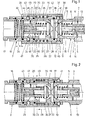
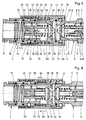
- Each quick release coupling basically consists of a plug valve 1 and a sleeve valve 2. Only a single embodiment is shown of the plug valve 1, while the sleeve valve shows a first embodiment in the upper half of the drawing and a second embodiment in all figures in the lower half of the drawing.
- the plug valve 1 consists essentially of a coupling body 3 with a seat 4.
- the star body 5 which has three protruding arms 6 distributed over the circumference, is mounted with the aid of the securing ring 7.
- the star body 5 is sleeve-shaped and has a central bore 8 in which the stem 9 of a valve body 10 is slidably guided.
- the valve body 10 forms with the seat 4 of the coupling body 3 a check valve 10, 4, which closes the line in question, which is connected to the plug valve 1, as can be seen.
- the valve body 10 is pressed against the seat 4 by means of a closing spring 11, which on the other hand holds the star body 5 in contact with the locking ring 7.
- the valve body 10 projects beyond the end wall 12 of the plug valve 1 by the dimension a '.
- the adjusting screw 13 is also supported by means of a thread, the front end of which forms a stop 14 for the end of the shaft 9 or the valve body 10.
- the adjusting screw 13 is set in the star body 5 by means of the thread so that the stop 14 is at a distance a 'from the end of the stem 9 of the valve body 10.
- the valve body 10 can thus cover the valve stroke a 'between its open position and its closed position.
- the coupling body 3 has a circumferential locking groove 15 at the point shown, which with a locking ball lock to be described later for locking the plug valve 1 with the sleeve valve 2 in the coupled position and for releasing the two Parts 1, 2 cooperate in the uncoupled position.
- the sleeve valve 2 now also has a coupling body 16 which is screwed onto a connecting piece 17, a seal 18 sealing the interior in a pressure-tight manner.
- a seat sleeve 19 is slidably mounted in the coupling body 16, in which a star body 20 is mounted with the aid of the locking ring 21.
- the seat sleeve 19 carries the seat 22.
- the star body 20 is slidably mounted directly in the coupling body 16.
- the star body 20 in the second embodiment has a sliding sleeve 23.
- the star body 20 has, for example, three radially projecting arms 24, between which the flow can take place over the circumference.
- the seat 22 is formed by the coupling body 16.
- a bore 25 is also provided on the sleeve valve 2 in the center of the star body 20, which bores the shaft 26 of the valve body 27.
- the valve body 27 forms with the seat 22 the check valve 22, 27 of the socket valve 2.
- the front end of the valve body 27 protrudes beyond the end plane 28 by the dimension a.
- an adjusting screw 29 is arranged so as to be adjustable and adjustable with the aid of a thread, the front end of which forms a stop 30 for the rear end of the shaft 26 or the valve body 27.
- the adjusting screw 29 is set so that the valve body 27 can perform the valve stroke a when opening before it strikes the stop 30 with its shaft 26.
- the closing spring 31 is switched on between the star body 20 and the valve body 27.
- valve stroke a of the sleeve valve 2 corresponds approximately to the valve stroke a 'of the plug valve 1. Both valve strokes a and a' differ only by tolerances due to the manufacturing process. Basically, the same level is aimed at and set during production.
- the star body 20 is mounted in the upper embodiment via the seat sleeve 19 or with this and in the lower embodiment directly via its sliding sleeve 23 in the coupling body 16, the two seals 32 and 33 being arranged for sealing purposes. In both cases it is achieved that the star body 20 is axially displaceable by the dimension b relative to the coupling body 16.
- the dimension b is at least the same size as the valve stroke a '(or a), but has been chosen larger in order to facilitate production. In any case, this makes it possible for the valve body 27 of the sleeve valve 2 to be mounted displaceably overall by twice the valve stroke 2a, while the valve body 10 of the plug valve 1 can only be displaced by the simple valve stroke a '.
- the star body 20 with its sliding sleeve 23 or the separate seat sleeve 19 are supported by a compression spring 34 on the connector 17 or on a shoulder of the coupling body 16.
- the force of the compression spring 34 is selected to be greater than the force of the closing spring 31, so that a clear chronological sequence of the relative movements is defined in this way.
- the coupling body 16 is surrounded by a sliding sleeve 35, which is designed here as a common sliding sleeve and serves to actuate two different locking ball locks, as will be explained in the following.
- the sliding sleeve 35 is slidably mounted on the coupling body 16 with the aid of the spring 36 in both directions.
- the entire quick release coupling is designed as a so-called pull-push coupling, i. H. the sliding sleeve 35 can be moved in both directions with respect to the coupling body for the purpose of releasing the two locking ball locks.
- the sliding sleeve 35 has a relatively wide locking cam 37, to which two escape grooves 38 and 39 connect in both directions.
- the coupling body 16 has, in a manner known per se, a series of radial openings 40 in which balls 41 are mounted.
- the locking cam 37 forms in connection with the evasion grooves 38, 39, the balls 41 and the locking groove 15 of the plug valve 1, a first locking ball lock 15, 37, 38, 39, 40, 41, which is used to lock the plug valve 1 and sleeve valve 2 in the coupled position or to release the two parts in the uncoupled position. Locking ball locks of this type are known per se and therefore do not require any further description.
- the further seal 42 is accommodated on the coupling body 16 of the socket valve 2.
- the common sliding sleeve 35 also serves to actuate a second locking ball lock.
- the sliding sleeve 35 has a further circumferential locking cam 43, which is comparatively less wide than the locking cam 37.
- a circumferentially annular locking cam 43 is axially displaceably mounted on the sliding sleeve 35 and can be made comparatively less wide than the locking cam 37.
- the locking cam 43 there are in turn escape grooves 44 and 45 on both sides.
- the coupling body 16 (FIGS. 1 to 8) has a plurality of openings 46 arranged around the circumference for receiving the balls 47.
- a circumferential locking groove 48 is in the seat sleeve 19 or in the sliding sleeve 23 of the star body 20 incorporated outside.
- the locking cam 43 forms in connection with the evading grooves 44, 45, the openings 46 in the coupling body 16, the balls 47 and the locking groove 48, the second locking ball lock 43 to 48, which for locking the star body 20 relative to the coupling body 16 or in its other position Release serves.
- the second locking ball lock 43 to 48 forms an engaging and disengaging stop for limiting or releasing the axial movement of the valve body 27.
- valve body 27 can cover a maximum of the simple valve lift a, if a corresponding force is exerted on the tip of the valve body 27, which leads to overcoming the force of the closing spring 31. If, on the other hand, the second locking ball lock 43 to 48 is disengaged or released, as shown, for example, in FIG. 2, the valve body 27 can not only perform the single valve lift a, but can also cover the double valve lift relative to the end plane 28, which is the sum of the two of the individual valve strokes a + a'z2-a.
- the evasion grooves 44 and 45 form an axially continuous recess in which the annular locking cam 43 is axially displaceably supported relative to the common sliding sleeve 35 and acted upon by two springs 54 and 55 in the direction of the axial central position of its stroke is.
- the pressure medium flows through the spaces between the arms 24 via the open check valve 22, 27 against the valve body 10 and additionally loads it against the force of the closing spring 11 and the pressure locked there.
- the pressure of the compression spring 34 acts on the valve body 10 via the valve body 27, so that an overall opening movement of the check valve 10, 4 takes place in all cases or at a corresponding pressure level, so that the pressure compensation is established.
- this pressure also acts on the rear of the valve body 27, this movement being supported by the force of the compression spring 34.
- valve body 27 again moves to the right by the simple valve stroke a ', the valve body 10 being carried along and of course also performing the simple valve stroke a' until its stem 9 comes to rest on the fixed stop 14.
- This position of the parts is shown in Fig. 4.
- the sliding sleeve 23 of the star body 20 also moves so far to the right that the locking groove 48 is in the region of the balls 47 arrives, so that in addition to the first locking ball lock, the second ball lock 43 to 48 can now also close.
- This closed position is made possible in the embodiments of FIGS. 5 to 8 by the axially displaceable mounting of the locking cam 43 and the force of the spring 54.
- Both the first locking ball lock 15, 37 to 41 and the second locking ball lock 43 to 48 are then in the locked position, as shown in FIGS. 4 and 8, respectively.
- a further marking 52 (FIG. 4) on the outer circumference of the coupling body 16 is thus visible relative to the end of the sliding sleeve 35 when it has shifted into the end position shown in FIG.
- the outer circumference of the sliding sleeve 35 in connection with a recess 56 indicates that the locking cam 43 has moved according to arrow 53 into the end position shown in FIG. 8.
- the markings 51 and 52 reliably indicate that both locking ball locks are locked. This means that the stop 30 is also engaged again, ie it is effective.
- the two valve bodies 10 and 27 are thus in a firmly locked position between the stops 14 and 30, so that pressure fluctuations in the pressure medium cannot lead to any significant displacement of the valve bodies 10, 27 in parts 1, 2 of the quick-action coupling.
- the end face 12 of the plug valve 1 and the end face 28 of the socket valve 2 assume a common end face level in the coupled position, as shown in FIG. 4.
- the sliding sleeve 35 is actuated from the position according to FIGS. 4 to 8 either in the direction of the arrows 49 or in the opposite direction, so that the two locking ball locks 15, 37 to 41 and 43 to 48 are unlocked.
- the plug valve 1 is pushed out of the sleeve valve 2, with both check valves 20, 4 and 22, 27 moving into the closed position, as shown in FIGS. 1 and 5.
- FIGS. 1 to 4 or 5 to 8 in the upper half has an analogous mode of operation, in which case the star body 20 is displaced together with the seat sleeve 19.
- the drawings show the various intermediate positions provided that the compression spring 34 is designed to be stronger than the closing spring 31. On the other hand, if the closing spring 31 is made stronger than the compression spring 34, this would result in a somewhat different mode of operation. In the intermediate position according to FIGS. 2 and 6, there would then be the possibly desired advantage that both check valves 4, 10 and 22, 27 would be closed in this intermediate position.
- the quick-release coupling can of course also be coupled and uncoupled if neither of the two lines respectively connected to the plug valve 2 and the socket valve 2 are under pressure during the coupling or uncoupling process.
- the springs 11, 31, 34 depending on the coordination of the springs 11, 31, 34, a different sequence of movements of the individual valve bodies relative to the coupling bodies 3 and 16 occurs.
- the valve body 10 will perform the simple valve lift a 'during the coupling process without pressure, while the valve body 27 does the same simple valve lift a executes, so that the open position of the two check valves 4, 10 and 22, 27 is reached according to FIG. 4. But even in this case the locking position is reached immediately when the coupling process is finished and the sliding sleeve has reached its end position. The passage through the quick release coupling is open and remains open because the valve bodies are locked before the pressure source is switched on. A one-time closing operation in the sense of a double lifting movement is no longer necessary to reach the locking position.
Landscapes
- Engineering & Computer Science (AREA)
- General Engineering & Computer Science (AREA)
- Mechanical Engineering (AREA)
- Quick-Acting Or Multi-Walled Pipe Joints (AREA)
Claims (10)
Priority Applications (1)
| Application Number | Priority Date | Filing Date | Title |
|---|---|---|---|
| AT81100845T ATE11332T1 (de) | 1980-02-14 | 1981-02-06 | Auch unter druck kuppelbare schnellverschlusskupplung. |
Applications Claiming Priority (4)
| Application Number | Priority Date | Filing Date | Title |
|---|---|---|---|
| DE3005490 | 1980-02-14 | ||
| DE19803005490 DE3005490C2 (de) | 1980-02-14 | 1980-02-14 | Auch unter Druck kuppelbare Schnellverschlußkupplung |
| DE19803039072 DE3039072C2 (de) | 1980-10-16 | 1980-10-16 | Auch unter Druck kuppelbare Schnellverschlußkupplung |
| DE3039072 | 1980-10-16 |
Publications (3)
| Publication Number | Publication Date |
|---|---|
| EP0034312A2 EP0034312A2 (fr) | 1981-08-26 |
| EP0034312A3 EP0034312A3 (en) | 1982-05-12 |
| EP0034312B1 true EP0034312B1 (fr) | 1985-01-16 |
Family
ID=25783712
Family Applications (1)
| Application Number | Title | Priority Date | Filing Date |
|---|---|---|---|
| EP19810100845 Expired EP0034312B1 (fr) | 1980-02-14 | 1981-02-06 | Accouplement à action rapide accouplable aussi sous pression |
Country Status (4)
| Country | Link |
|---|---|
| US (1) | US4388947A (fr) |
| EP (1) | EP0034312B1 (fr) |
| DK (1) | DK150388C (fr) |
| ES (1) | ES8201714A1 (fr) |
Cited By (2)
| Publication number | Priority date | Publication date | Assignee | Title |
|---|---|---|---|---|
| DE3632967A1 (de) * | 1986-09-27 | 1988-04-07 | Wws Wohnwaerme Service Gebr Le | Verschluss- und kupplungsvorrichtung |
| DE19953243A1 (de) * | 1999-11-04 | 2001-05-17 | Voswinkel Kg | Unter Druck kuppelbare Schnellverschlußkupplung |
Families Citing this family (29)
| Publication number | Priority date | Publication date | Assignee | Title |
|---|---|---|---|---|
| ES8702623A1 (es) * | 1985-04-24 | 1987-01-01 | Schmelzer Corp | Un conjunto de acoplamiento de conexion para conectar de manera liberable un par de conductos de fluido entre si. |
| US4583711A (en) * | 1985-06-28 | 1986-04-22 | Parker-Hannifin Corporation | Rigid mount coupler with flow check stop |
| US4842309A (en) * | 1987-05-20 | 1989-06-27 | Schmelzer Corporation | Quick-connect fluid fitting assembly |
| IT1215734B (it) * | 1988-01-19 | 1990-02-22 | Faster Srl | Innesto rapido perfezionato, innestabile con maschio in pressione ed atto a garantire il flusso nei due sensi, senza pericolo di interruzione. |
| IT1218077B (it) * | 1988-06-15 | 1990-04-12 | Dideco Spa | Dispositivo di intercettazione di fluido in una linea |
| SE469989B (sv) * | 1989-01-19 | 1993-10-18 | Nyberg Bo Erik | Ventilanordning vid snabbkopplingar för exempelvis högtrycksolja |
| US4971110A (en) * | 1989-12-19 | 1990-11-20 | Semi-Gas Systems, Inc. | Face seal shut-off valve |
| JPH0753031Y2 (ja) * | 1991-03-26 | 1995-12-06 | 日東工器株式会社 | 試料採取配管用管継手 |
| US5255699A (en) * | 1992-12-07 | 1993-10-26 | Parker-Hannifin Corporation | Nipple with integral crossbar actuator and check valve |
| US6029701A (en) * | 1995-09-19 | 2000-02-29 | Parker Hannifin Sa | Quick-connect coupling for pressurized fluid lines |
| SE510095C2 (sv) * | 1996-02-23 | 1999-04-19 | Dart Engineering Ag | Anordning vid snabbkoppling |
| IT1289947B1 (it) * | 1997-02-21 | 1998-10-19 | Faster Srl | Innesto rapido |
| ITGE20010006U1 (it) * | 2001-03-30 | 2002-09-30 | Htm Sport Spa | Dispositivo di tensionamento della cinghia di assicurazione delle bombole di gas compreso allo schienalino di un jacket o simili per attivit |
| GB0116989D0 (en) * | 2001-07-12 | 2001-09-05 | Chamberlain Luke | Boiler unit |
| FR2855239B1 (fr) * | 2003-05-20 | 2005-08-12 | Parker Hannifin Sa | Raccord rapide pour conduites de fluide hydraulique |
| FR2889728B1 (fr) * | 2005-08-10 | 2007-10-05 | Staubli Faverges Sca | Ensemble de raccord pour circuit fluidique |
| GB2431702B (en) * | 2005-10-25 | 2008-06-04 | Diamould Ltd | Connection device for an underwater service line and associated mounting and ROV handle assemblies |
| FR2895058B1 (fr) * | 2005-12-20 | 2008-03-14 | Parker Hannifin France Sas Soc | Coupleur rigide pour conduites de fluide sous pression, permettant la connexion de ces conduites alors que du fluide sous pression subsiste dans l'une d'elles |
| WO2009107790A1 (fr) * | 2008-02-28 | 2009-09-03 | 日東工器株式会社 | Emboîture pour joint de tuyau et joint de tuyau |
| TW200949121A (en) * | 2008-02-28 | 2009-12-01 | Nitto Kohki Co | Socket for pipe coupling and pipe coupling |
| CN104684385A (zh) * | 2012-01-07 | 2015-06-03 | Ivm知识产权有限公司 | 液体涂敷器装置 |
| BR102013016280A2 (pt) * | 2013-06-25 | 2015-08-18 | Dynamics Do Brasil Metalurgia Ltda | Aperfeiçoamento em engate hidráulico para acoplamento rápido |
| US9887478B2 (en) * | 2015-04-21 | 2018-02-06 | Varian Semiconductor Equipment Associates, Inc. | Thermally insulating electrical contact probe |
| WO2017069949A1 (fr) * | 2015-10-22 | 2017-04-27 | Parker-Hannifin Corporation | Raccord rapide avec passage à déplacement volumique |
| FR3046209B1 (fr) * | 2015-12-23 | 2018-02-16 | Staubli Faverges | Element femelle de raccord rapide et raccord rapide comprenant un tel element femelle |
| US9899193B1 (en) | 2016-11-02 | 2018-02-20 | Varian Semiconductor Equipment Associates, Inc. | RF ion source with dynamic volume control |
| FR3080165B1 (fr) * | 2018-04-12 | 2020-05-01 | Staubli Faverges | Element de raccord et raccord comprenant un tel element de raccord |
| JP7150310B2 (ja) * | 2018-07-27 | 2022-10-11 | サーパス工業株式会社 | 流体移送用コネクタ及びその制御方法 |
| CN109538861A (zh) * | 2019-01-16 | 2019-03-29 | 山西双环重工集团有限公司 | 液压接头 |
Family Cites Families (11)
| Publication number | Priority date | Publication date | Assignee | Title |
|---|---|---|---|---|
| GB1132383A (en) * | 1966-03-29 | 1968-10-30 | Exactor Sterling Ltd | Fluid line self sealing coupling |
| US3482602A (en) * | 1967-08-08 | 1969-12-09 | Noble Mfg Co | Hydraulic coupler |
| US3674051A (en) * | 1971-05-14 | 1972-07-04 | Safe Way Hydraulics | Hydraulic coupler |
| US3791411A (en) * | 1972-08-18 | 1974-02-12 | B Bogeskov | Hydraulic coupler |
| DE2642724C2 (de) * | 1976-09-23 | 1983-11-24 | Fischer, Wolf E., 7505 Ettlingen | Kupplung zur Verbindung von Hydraulikleitungen |
| US4098292A (en) * | 1977-01-24 | 1978-07-04 | Aeroquip Corporation | Locking means for self-sealing quick disconnect couplings |
| CH626696A5 (fr) * | 1977-03-19 | 1981-11-30 | Argus Gmbh | |
| DE2712117C2 (de) * | 1977-03-19 | 1985-01-24 | Argus Gesellschaft Mbh, 7505 Ettlingen | Schnellverschlußkupplung für Hydraulikleitungen |
| DE2715417A1 (de) * | 1977-04-06 | 1978-10-12 | Argus Gmbh | Schnellverschlusskupplung fuer hydraulikleitungen |
| DE2724630C3 (de) * | 1977-06-01 | 1980-01-24 | Robert Volker Ing.(Grad.) 7502 Malsch Pfeiffer | Rohrleitungskupplung, insbesondere für Hoch- und Höchstdruckleitungen |
| DE2741027A1 (de) * | 1977-09-12 | 1979-03-22 | Fischer Wolf E Dipl Ing | Unter druck kuppelbare verbindungskupplung |
-
1981
- 1981-02-06 EP EP19810100845 patent/EP0034312B1/fr not_active Expired
- 1981-02-11 US US06/233,659 patent/US4388947A/en not_active Expired - Lifetime
- 1981-02-13 DK DK62981A patent/DK150388C/da active
- 1981-02-13 ES ES500073A patent/ES8201714A1/es not_active Expired
Cited By (3)
| Publication number | Priority date | Publication date | Assignee | Title |
|---|---|---|---|---|
| DE3632967A1 (de) * | 1986-09-27 | 1988-04-07 | Wws Wohnwaerme Service Gebr Le | Verschluss- und kupplungsvorrichtung |
| DE19953243A1 (de) * | 1999-11-04 | 2001-05-17 | Voswinkel Kg | Unter Druck kuppelbare Schnellverschlußkupplung |
| DE19953243C2 (de) * | 1999-11-04 | 2003-10-23 | Voswinkel Kg | Unter Druck kuppelbare Schnellverschlußkupplung |
Also Published As
| Publication number | Publication date |
|---|---|
| EP0034312A2 (fr) | 1981-08-26 |
| US4388947A (en) | 1983-06-21 |
| ES500073A0 (es) | 1981-12-16 |
| EP0034312A3 (en) | 1982-05-12 |
| DK150388B (da) | 1987-02-16 |
| ES8201714A1 (es) | 1981-12-16 |
| DK62981A (da) | 1981-08-15 |
| DK150388C (da) | 1987-10-19 |
Similar Documents
| Publication | Publication Date | Title |
|---|---|---|
| EP0034312A2 (fr) | Accouplement à action rapide accouplable aussi sous pression | |
| DE69003467T2 (de) | Schnellvervindungs- und Schnellöse-Kupplung. | |
| EP0381069B1 (fr) | Manchon d'accouplement pour lignes d'interconnexion hydraulique | |
| EP0038056B1 (fr) | Accouplement à action rapide pour tuyaux souples ou analogues | |
| EP2427683B1 (fr) | Pièce de raccordement | |
| EP0013393A1 (fr) | Raccord pour conduites | |
| DE1957879C3 (de) | Abreißkupplung für Strömungsmittelleitungen | |
| EP0191384B1 (fr) | Soupape d'assemblage | |
| DE19619839C1 (de) | Hydraulikkupplung | |
| EP0278420B1 (fr) | Raccord du type rapide en particulier pour conduites hydrauliques | |
| DE4025385C2 (fr) | ||
| EP0184799A2 (fr) | Raccord de ventilation | |
| EP0096649B1 (fr) | Accouplement jonctionnable du type à action rapide sous pression comme sans pression en particulier pour conduites hydrauliques | |
| DE3005490C2 (de) | Auch unter Druck kuppelbare Schnellverschlußkupplung | |
| DE3015601C2 (de) | Schnellverschlußkupplung für insbesondere Hydraulikleitungen | |
| EP1793154A2 (fr) | Partie femelle de raccord pneumatique à évent | |
| EP0051201A1 (fr) | Accouplement pour systèmes hydrauliques | |
| DE3410967C2 (fr) | ||
| DE3039072C2 (de) | Auch unter Druck kuppelbare Schnellverschlußkupplung | |
| DE1675373C3 (de) | Kupplung für Leitungen strömender Medien | |
| EP0187238A1 (fr) | Raccord de tuyau amovible pouvant également se raccorder si le connecteur est sous pression, en particulier pour conduits hydrauliques | |
| DE4318840C2 (de) | Kupplung zum Verbinden von Hydraulikleitungen | |
| DE3728577C2 (fr) | ||
| DE1068962B (fr) | ||
| DE3637176A1 (de) | Leckfreie hydraulik-kupplung |
Legal Events
| Date | Code | Title | Description |
|---|---|---|---|
| PUAI | Public reference made under article 153(3) epc to a published international application that has entered the european phase |
Free format text: ORIGINAL CODE: 0009012 |
|
| AK | Designated contracting states |
Designated state(s): AT BE CH FR GB IT LU NL SE |
|
| 17P | Request for examination filed |
Effective date: 19811012 |
|
| PUAL | Search report despatched |
Free format text: ORIGINAL CODE: 0009013 |
|
| AK | Designated contracting states |
Designated state(s): AT BE CH FR GB IT LU NL SE |
|
| ITF | It: translation for a ep patent filed | ||
| GRAA | (expected) grant |
Free format text: ORIGINAL CODE: 0009210 |
|
| AK | Designated contracting states |
Designated state(s): AT BE CH FR GB IT LU NL SE |
|
| REF | Corresponds to: |
Ref document number: 11332 Country of ref document: AT Date of ref document: 19850215 Kind code of ref document: T |
|
| ET | Fr: translation filed | ||
| PLBE | No opposition filed within time limit |
Free format text: ORIGINAL CODE: 0009261 |
|
| STAA | Information on the status of an ep patent application or granted ep patent |
Free format text: STATUS: NO OPPOSITION FILED WITHIN TIME LIMIT |
|
| 26N | No opposition filed | ||
| ITTA | It: last paid annual fee | ||
| EPTA | Lu: last paid annual fee | ||
| EAL | Se: european patent in force in sweden |
Ref document number: 81100845.7 |
|
| PGFP | Annual fee paid to national office [announced via postgrant information from national office to epo] |
Ref country code: FR Payment date: 20000118 Year of fee payment: 20 |
|
| PGFP | Annual fee paid to national office [announced via postgrant information from national office to epo] |
Ref country code: GB Payment date: 20000202 Year of fee payment: 20 |
|
| PGFP | Annual fee paid to national office [announced via postgrant information from national office to epo] |
Ref country code: BE Payment date: 20000218 Year of fee payment: 20 Ref country code: AT Payment date: 20000218 Year of fee payment: 20 Ref country code: CH Payment date: 20000218 Year of fee payment: 20 Ref country code: LU Payment date: 20000218 Year of fee payment: 20 Ref country code: SE Payment date: 20000218 Year of fee payment: 20 |
|
| PGFP | Annual fee paid to national office [announced via postgrant information from national office to epo] |
Ref country code: NL Payment date: 20000223 Year of fee payment: 20 |
|
| BE20 | Be: patent expired |
Free format text: 20010206 *AERPQUIP G.M.B.H. |
|
| PG25 | Lapsed in a contracting state [announced via postgrant information from national office to epo] |
Ref country code: LI Free format text: LAPSE BECAUSE OF EXPIRATION OF PROTECTION Effective date: 20010205 Ref country code: CH Free format text: LAPSE BECAUSE OF EXPIRATION OF PROTECTION Effective date: 20010205 Ref country code: GB Free format text: LAPSE BECAUSE OF EXPIRATION OF PROTECTION Effective date: 20010205 |
|
| PG25 | Lapsed in a contracting state [announced via postgrant information from national office to epo] |
Ref country code: NL Free format text: LAPSE BECAUSE OF EXPIRATION OF PROTECTION Effective date: 20010206 Ref country code: LU Free format text: LAPSE BECAUSE OF EXPIRATION OF PROTECTION Effective date: 20010206 Ref country code: AT Free format text: LAPSE BECAUSE OF EXPIRATION OF PROTECTION Effective date: 20010206 |
|
| PG25 | Lapsed in a contracting state [announced via postgrant information from national office to epo] |
Ref country code: SE Free format text: THE PATENT HAS BEEN ANNULLED BY A DECISION OF A NATIONAL AUTHORITY Effective date: 20010207 |
|
| REG | Reference to a national code |
Ref country code: CH Ref legal event code: PL Ref country code: GB Ref legal event code: PE20 Effective date: 20010205 |
|
| NLV7 | Nl: ceased due to reaching the maximum lifetime of a patent |
Effective date: 20010206 |
|
| EUG | Se: european patent has lapsed |
Ref document number: 81100845.7 |