EP0034357A2 - Flugzeug mit einer Notrutsche - Google Patents
Flugzeug mit einer Notrutsche Download PDFInfo
- Publication number
- EP0034357A2 EP0034357A2 EP81101057A EP81101057A EP0034357A2 EP 0034357 A2 EP0034357 A2 EP 0034357A2 EP 81101057 A EP81101057 A EP 81101057A EP 81101057 A EP81101057 A EP 81101057A EP 0034357 A2 EP0034357 A2 EP 0034357A2
- Authority
- EP
- European Patent Office
- Prior art keywords
- slide
- inflatable
- flap
- escape
- walkway
- Prior art date
- Legal status (The legal status is an assumption and is not a legal conclusion. Google has not performed a legal analysis and makes no representation as to the accuracy of the status listed.)
- Withdrawn
Links
Images
Classifications
-
- A—HUMAN NECESSITIES
- A62—LIFE-SAVING; FIRE-FIGHTING
- A62B—DEVICES, APPARATUS OR METHODS FOR LIFE-SAVING
- A62B1/00—Devices for lowering persons from buildings or the like
- A62B1/20—Devices for lowering persons from buildings or the like by making use of sliding-ropes, sliding-poles or chutes, e.g. hoses, pipes, sliding-grooves, sliding-sheets
-
- B—PERFORMING OPERATIONS; TRANSPORTING
- B64—AIRCRAFT; AVIATION; COSMONAUTICS
- B64D—EQUIPMENT FOR FITTING IN OR TO AIRCRAFT; FLIGHT SUITS; PARACHUTES; ARRANGEMENT OR MOUNTING OF POWER PLANTS OR PROPULSION TRANSMISSIONS IN AIRCRAFT
- B64D25/00—Emergency apparatus or devices, not otherwise provided for
- B64D25/08—Ejecting or escaping means
- B64D25/14—Inflatable escape chutes
Definitions
- This invention relates to an inflatable aircraft evacuation system and especially to an inflatable slide adapted to extend from a supporting surface such as an aircraft wing.
- This type of system requires the passengers to climb out on the wing surface and part of the slide before they reach the inclined surface of the slide. It is therefore important that the walking surface provide the necessary firmness and stability.
- Another requirement is to provide support of the wing mounted slide with the wing flap in the different operating positions of the wing flap so that the proper position of the slide will be maintained and . especially if the evacuation is required with the flap set for landing.
- an escape slide having an entrance ramp adaptable to rest on an inclined surface and being inflatable to provide the necessary rigidity of footing to support passengers entering and walking on the ramp.
- Another aspect of this invention is to provide support for the slide by the wing flap at any position of the flap.
- a further aspect of the invention is to provide a visible indicator which can be seen from the aircraft to indicate whether or not the slide is properly inflated and ready for use in evacuating passengers from the aircraft.
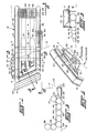
- a multitubular inflatable escape slide 10 is shown in the inflated condition in position for evacuating passengers from an aircraft fuselage 11 on which an escape slide supporting surface such as aircraft wing 12 is mounted.
- the escape slide 10 has an inflatable relatively horizontal entrance portion 13 positioned on the wing 12 and an inclined inflatable slide portion 14 shown in position for evacuating passengers from the aircraft.
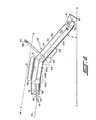
- the slide portion 14 is positioned at an angle A to the ground in the normal condition of the aircraft.
- the angle A of the slide portion 14 is about 43 degrees to the horizontal or ground line G-G.
- the slide portion 14 extends from an entrance end 15 adjacent the entrance portion 13 to an exit end 16 at the lower end of the slide which is supported by the ground surface at the ground line G-G.
- the escape slide 10 has a walkway 17 extending from the entrance end 15 of the slide portion 14 to an edge 18 where the passengers enter the slide.
- a walkway ramp 19 may be fastened to the edge 18 for facilitating movement of the passengers from the wing 12 onto the escape slide 10.
- the escape slide 10 is fastened to the fuselage 11 through a packboard 22 which is pivotally mounted on the fuselage about an axis A-A for rotation of the packboard and the packaged escape slide 10 from a position within a compartment 23 in the wall of the fuselage 11 to a position on the wing 12 as shown in Figs. 3, 4 and 5.
- the escape slide 10 is inflated by a suitable inflation system such as-turbofans 24 and 25 mounted on the packboard and connected to the escape slide by inflating conduits 26 and 27, respectively.
- the packboard 22 has a girt strap 28 for attachment to the escape slide 10 to hold it in position on the wing 22.
- the escape slide 10 has a multitublar construction including a left-hand lower side tube 29, a right-hand lower side tube 32, and a central main tube 33, all of which extend longitudinally of the escape slide through the entrance portion 13 and the slide portion 14.
- the lower side tubes 29 and 32 are connected by an upper transverse tube 34 and a lower transverse tube 35.
- the escape slide 10 also has a longitudinally extending left-hand upper side rail tube 36 mounted on top of the left-hand lower side tube 29 and a right-hand upper side rail tube 37 mounted on the right-hand lower side tube 32.
- the left-hand upper side rail tube 36 and right-hand upper side rail tube 37 are connected at the edge 18 of the entrance portion 13 by a U-shaped transverse upper tube 38 and by a U-shaped transverse lower tube 39 at the exit end 16 of the slide portion 14, both of which are mounted alongside the upper transverse tube 34 and lower transverse tube 35.
- a center panel 42 is fastened to the lower side tubes 29 and 32 and to the central main tube 33.between the upper side rail tubes 36 and 37 providing a slide surface in the slide portion 14 and a walking surface along the walkway 17.
- the lower side tubes 29 and 32 are spaced from the central main tube 33 and in the entrance portion 13 these spaces are filled by walkway supporting tubes 43 and 44 extending from the upper tranverse tube 34 to the entrance end 15 of the slide portion 14 providing a plurality of supporting tubes in side-by-side relationship under the walkway 17.
- These supporting tubes 29, 32, 33, 43 and 44 as well as the upper transverse tube 34 and U-shaped transverse upper tube 38 are located above a plane such as the plane of the wing 12 to provide a stable support for persons traversing the walkway 17 to the entrance end 15 of the slide portion 14. All of these supporting tubes are also positioned below the walkway 17 to provide unimpeded travel of the passengers over the walkway.
- An inflatable support means such as pillow member 45 is mounted on the bottom of the slide portion 14 at the entrance end 15, as shown in Figs. 1 and 2, in a position for engagement with a flap 46 of the wing 12 in an extended position such as the position taken during landing of the aircraft.
- the edge of the flap 46 engages the lower side of the escape slide 10 and provides support for the slide portion at the entrance end 15.
- Additional supporting means such as pillow members 47 and 48 may be mounted between the central main tube 33 and lower side tubes 29 and 32 for engagement with the pillow member 45 to provide further support of the escape slide in the slide portion 14.
- the walkway ramp 19 is mounted on the U-shaped transverse upper tube 38 and has an upper surface 49 and a lower surface 52 connected by bulkheads 53, 54 and 55 forming transverse tubular spaces.
- the upper surface 49 is inclined from the walkway 17 at the edge 18 of the entrance portion 13 so as to facilitate walking of the passengers from the surface of the wing 12 to the walkway.
- the bulkheads 54 and 55 in close proximity to the edge 18 of the entrance portion 13 have a greater length than the bulkhead 53 at a position remote from the edge so that upon inflation of the ramp 19, the upper surface 49 will have the desired inclination.
- the ramp 19 is mounted on and connected to the U-shaped transverse upper tube 38.
- a top side rail 56 may be mounted on top the left-hand upper side rail tube 36, as shown in Figs. 1, 2 and 3.
- the turbofan 24 and conduit 26 are connected to the lower side tubes 29,32, the central main tube 33, the walkway supporting tubes 43, 44 and pillow members 45, 47 and 48 in a first inflation system.
- the turbofan 25 and conduit 27 are connected to upper rail tubes 36,37, U-shaped transverse tubes 38 and 39, walkway ramp L9 and top side rail tube 56 in a second inflation system. With the two independent systems, the slide 10 nay still be usable if one of the systems is inoperable.
- inflatable indicator tubes 57 and 58 are mounted on the left-hand Lower side tube 29 and left-hand upper side rail tube 36, respectively.
- the indicator tubes 57 and 58 Upon inflation of the lower and ipper inflatable systems, the indicator tubes 57 and 58 will be inflated and extend upwardly beyond a line of sight S-S, shown in chain-dotted lines in Fig. 2, of a flight attendant from the fuselage access door. The attendant can thereby tell by looking from within the fuselage whether the slide portion 14 is inflated and extended so as to evacuate the passengers safely from the aircraft. If either the lower inflatable system or upper inflatable system is damaged and not inflated, the appropriate indicator tubes 57 or 58 will not be inflated and this will be evident from inside the fuselage 11.
- the indicator tubes 57 and 58 have a sufficient diameter to provide rigidity and extend above the line of sight S-S while at the same time they have a diameter which is small enough to require a minimum of inflatable gas.
- Marking tape 59 and 60 which may be of a highly visible material, may be wrapped around the ends of the indicator tubes 57 and 58 to make them more visible to the aircraft attendant.
- the packboard 22 may be extended and the escape slide 10 inflated by suitable controls from within the fuselage 11.
- the attendant then can look out the access door of the fuselage 11 and by observing the positions of the indicator tubes 57 and 58 determine if the slide portion 14, which is not visible from the fuselage, is in condition for evacuating passengers.
- the passengers may then walk on the surface of the wing 12 up the ramp 19 and over walkway 17 to the entrance end 15 of the slide portion 14. They may then slide on the center panel 42 from the entrance end to the exit end 16 of the slide portion.
- the turbofans 24 and 25 inflate the upper and lower inflation systems of the escape slide 10 in about two seconds inflation time to a pressure of about three pounds per square inch (0.21 kilograms per square centimeter).
- the escape slide 10 may be constructed of a suitable flexible material such as square-woven nylon impregnated with neoprene to retain air or other inflation medium in the inflatable parts.
Landscapes
- Business, Economics & Management (AREA)
- Emergency Management (AREA)
- Health & Medical Sciences (AREA)
- General Health & Medical Sciences (AREA)
- Engineering & Computer Science (AREA)
- Aviation & Aerospace Engineering (AREA)
- Emergency Lowering Means (AREA)
Applications Claiming Priority (2)
| Application Number | Priority Date | Filing Date | Title |
|---|---|---|---|
| US122216 | 1980-02-19 | ||
| US06/122,216 US4333546A (en) | 1980-02-19 | 1980-02-19 | Escape slide |
Publications (2)
| Publication Number | Publication Date |
|---|---|
| EP0034357A2 true EP0034357A2 (de) | 1981-08-26 |
| EP0034357A3 EP0034357A3 (de) | 1982-05-05 |
Family
ID=22401398
Family Applications (1)
| Application Number | Title | Priority Date | Filing Date |
|---|---|---|---|
| EP81101057A Withdrawn EP0034357A3 (de) | 1980-02-19 | 1981-02-14 | Flugzeug mit einer Notrutsche |
Country Status (4)
| Country | Link |
|---|---|
| US (1) | US4333546A (de) |
| EP (1) | EP0034357A3 (de) |
| JP (1) | JPS56135396A (de) |
| CA (1) | CA1138796A (de) |
Cited By (7)
| Publication number | Priority date | Publication date | Assignee | Title |
|---|---|---|---|---|
| US6003813A (en) * | 1997-09-10 | 1999-12-21 | The Boeing Company | Escape systems for aircraft overhead rest areas |
| US6799741B2 (en) * | 2002-06-21 | 2004-10-05 | Goodrich Corporation | Evacuation slide having trapezoidal outline |
| EP3031729A1 (de) * | 2014-12-10 | 2016-06-15 | Airbus Operations GmbH | Notrutsche mit einer leitmarkierung |
| EP3118118A1 (de) * | 2015-07-17 | 2017-01-18 | Goodrich Corporation | Steuerungsriemen für ein evakuierungssystem über einen flügel |
| EP3401221A1 (de) * | 2017-05-12 | 2018-11-14 | Goodrich Corporation | Evakuierungssystem mit windauftriebsabweiser |
| EP3967605A1 (de) * | 2020-09-12 | 2022-03-16 | Goodrich Corporation | Doppelsystem elektrisch angetriebener sauger |
| US11788537B2 (en) | 2020-09-12 | 2023-10-17 | Goodrich Corporation | Dual system electric powered aspirators |
Families Citing this family (21)
| Publication number | Priority date | Publication date | Assignee | Title |
|---|---|---|---|---|
| US4846422A (en) * | 1984-05-14 | 1989-07-11 | The Bfgoodrich Company | Single piece evacuation system for aircraft or the like |
| US4723628A (en) * | 1984-12-03 | 1988-02-09 | The B. F. Goodrich Company | Evacuation slide |
| US4684079A (en) * | 1985-12-13 | 1987-08-04 | The Garrett Corporation | Inflatable evacuation device |
| US5875868A (en) * | 1997-02-04 | 1999-03-02 | Air Cruisers Company | Inflatable evacuation slide |
| US6471001B1 (en) * | 1999-10-06 | 2002-10-29 | The B.F. Goodrich Corporation | Escape slide |
| US6443259B1 (en) * | 2001-10-11 | 2002-09-03 | Goodrich Corporation | Passive deployment readiness indicator for aircraft evacuation slide |
| US9309002B2 (en) | 2013-10-03 | 2016-04-12 | Air Cruisers Company | Evacuation slide readiness indicating systems |
| US9809316B2 (en) | 2015-09-25 | 2017-11-07 | Goodrich Corporation | Aircraft sill height compensating evacuation system |
| US10654575B1 (en) * | 2016-05-10 | 2020-05-19 | Air Cruisers Company, LLC | Off wing slide ramp |
| US10351251B2 (en) * | 2016-12-20 | 2019-07-16 | Goodrich Corporation | Audio evacuation system readiness indicator |
| US10000292B1 (en) * | 2017-07-28 | 2018-06-19 | Goodrich Corporation | Multipurpose lane divider for evacuation slide |
| US10822098B2 (en) * | 2018-03-23 | 2020-11-03 | Goodrich Corporation | Evacuation system inflatable toe end spring and sill height compensating feature |
| US11511871B2 (en) | 2019-09-24 | 2022-11-29 | Goodrich Corporation | Multipurpose readiness indicator for off-wing slide raft |
| US11345478B2 (en) | 2019-09-26 | 2022-05-31 | Goodrich Corporation | Evacuation slide and method of forming evacuation slide having integral cable channel |
| US11554871B2 (en) | 2020-01-06 | 2023-01-17 | Goodrich Corporation | Truss strap integrated geometric restraint |
| US11192658B2 (en) * | 2020-01-17 | 2021-12-07 | Goodrich Corporation | Evacuation slide ramp barrier readiness indicator |
| US11745880B2 (en) | 2020-01-17 | 2023-09-05 | Goodrich Corporation | Readiness indicator lights for evacuation slide |
| US11492129B2 (en) * | 2020-01-17 | 2022-11-08 | Goodrich Corporation | Evacuation slide with safety gate readiness indicator |
| CN111959797B (zh) * | 2020-08-25 | 2021-11-19 | 南京禹智智能科技有限公司 | 一种大型航空客机专用逃生救援设备 |
| US12134479B2 (en) | 2021-12-03 | 2024-11-05 | Goodrich Corporation | Readiness indicator light system having projection light for evacuation slide |
| US12509232B2 (en) | 2023-09-26 | 2025-12-30 | The Boeing Company | Aircraft evacuation slides |
Family Cites Families (7)
| Publication number | Priority date | Publication date | Assignee | Title |
|---|---|---|---|---|
| US3476338A (en) * | 1967-12-04 | 1969-11-04 | Goodrich Co B F | Inflatable ramp |
| US3656579A (en) * | 1970-09-08 | 1972-04-18 | Goodrich Co B F | Friction panel |
| US3692144A (en) * | 1970-11-18 | 1972-09-19 | Garrett Corp | Fluid distensible truss |
| US3845920A (en) * | 1972-01-14 | 1974-11-05 | Sargent Industries | Inflatable evacuation ramp |
| US3973645A (en) * | 1975-08-15 | 1976-08-10 | The Garrett Corporation | Inflatable evacuation slide |
| US4018321A (en) * | 1976-05-21 | 1977-04-19 | The B. F. Goodrich Company | Escape slide and platform assembly |
| GB1538084A (en) * | 1977-05-19 | 1979-01-10 | British Aircraft Corp Ltd | Passenger escape means |
-
1980
- 1980-02-19 US US06/122,216 patent/US4333546A/en not_active Expired - Lifetime
-
1981
- 1981-01-28 CA CA000369498A patent/CA1138796A/en not_active Expired
- 1981-02-14 EP EP81101057A patent/EP0034357A3/de not_active Withdrawn
- 1981-02-19 JP JP2231681A patent/JPS56135396A/ja active Pending
Cited By (12)
| Publication number | Priority date | Publication date | Assignee | Title |
|---|---|---|---|---|
| US6003813A (en) * | 1997-09-10 | 1999-12-21 | The Boeing Company | Escape systems for aircraft overhead rest areas |
| US6799741B2 (en) * | 2002-06-21 | 2004-10-05 | Goodrich Corporation | Evacuation slide having trapezoidal outline |
| EP3031729A1 (de) * | 2014-12-10 | 2016-06-15 | Airbus Operations GmbH | Notrutsche mit einer leitmarkierung |
| EP3118118A1 (de) * | 2015-07-17 | 2017-01-18 | Goodrich Corporation | Steuerungsriemen für ein evakuierungssystem über einen flügel |
| CN106347678A (zh) * | 2015-07-17 | 2017-01-25 | 古德里奇公司 | 离翼撤离系统控制带 |
| US9725181B2 (en) | 2015-07-17 | 2017-08-08 | Goodrich Corporation | Off wing evacuation system control strap |
| CN106347678B (zh) * | 2015-07-17 | 2020-10-30 | 古德里奇公司 | 离翼撤离系统控制带 |
| EP3401221A1 (de) * | 2017-05-12 | 2018-11-14 | Goodrich Corporation | Evakuierungssystem mit windauftriebsabweiser |
| US20180327101A1 (en) * | 2017-05-12 | 2018-11-15 | Goodrich Corporation | Evacuation system with wind lift deterrent |
| US10793280B2 (en) | 2017-05-12 | 2020-10-06 | Goodrich Corporation | Evacuation system with wind lift deterrent |
| EP3967605A1 (de) * | 2020-09-12 | 2022-03-16 | Goodrich Corporation | Doppelsystem elektrisch angetriebener sauger |
| US11788537B2 (en) | 2020-09-12 | 2023-10-17 | Goodrich Corporation | Dual system electric powered aspirators |
Also Published As
| Publication number | Publication date |
|---|---|
| JPS56135396A (en) | 1981-10-22 |
| US4333546A (en) | 1982-06-08 |
| EP0034357A3 (de) | 1982-05-05 |
| CA1138796A (en) | 1983-01-04 |
Similar Documents
| Publication | Publication Date | Title |
|---|---|---|
| EP0034357A2 (de) | Flugzeug mit einer Notrutsche | |
| US4332049A (en) | Escape slide and protective shield | |
| US4846422A (en) | Single piece evacuation system for aircraft or the like | |
| US4519782A (en) | Escape slide and life raft | |
| EP0034358B1 (de) | Notrutsche und Rettungsfloss | |
| US2765131A (en) | Inflatable escape chute assembly | |
| US4018321A (en) | Escape slide and platform assembly | |
| US4375877A (en) | Escape slide stowage and deployment system | |
| US5875868A (en) | Inflatable evacuation slide | |
| US3102623A (en) | Escape slide | |
| EP0636542B1 (de) | Aufblasbare Rutsche | |
| US3833088A (en) | Slide-raft for emergency aircraft evacuation | |
| US5975467A (en) | Inflatable evacuation slide | |
| US8215586B2 (en) | Evacuation slide systems | |
| EP0109610B1 (de) | Rutschbahn zur Notevakuierung | |
| EP2121443B1 (de) | Kombiniertes abführungsgleitsystem mit mehreren ausgängen | |
| US3679025A (en) | Inflatable slide and raft apparatus | |
| EP1302399B1 (de) | Passiver Indikator zur Anzeige des korrekten Auslösens einer Flugzeugnotrutsche | |
| US3973645A (en) | Inflatable evacuation slide | |
| EP0291355A2 (de) | Landungsvorrichtung eines Flugzeuges | |
| US3692144A (en) | Fluid distensible truss | |
| EP1431178B1 (de) | Notrutsche mit Spoiler an der Anströmkante | |
| EP0864493B1 (de) | Notrutsche mit Tragrohrvorrichtung | |
| US3476338A (en) | Inflatable ramp | |
| US3845920A (en) | Inflatable evacuation ramp |
Legal Events
| Date | Code | Title | Description |
|---|---|---|---|
| PUAI | Public reference made under article 153(3) epc to a published international application that has entered the european phase |
Free format text: ORIGINAL CODE: 0009012 |
|
| AK | Designated contracting states |
Designated state(s): DE FR GB |
|
| PUAL | Search report despatched |
Free format text: ORIGINAL CODE: 0009013 |
|
| AK | Designated contracting states |
Designated state(s): DE FR GB |
|
| 17P | Request for examination filed |
Effective date: 19820922 |
|
| STAA | Information on the status of an ep patent application or granted ep patent |
Free format text: STATUS: THE APPLICATION HAS BEEN WITHDRAWN |
|
| 18W | Application withdrawn |
Withdrawal date: 19850313 |
|
| RIN1 | Information on inventor provided before grant (corrected) |
Inventor name: FISHER, JOHN MELVIN |