EP0034362A2 - Machine à rectifier les garnitures de frein - Google Patents
Machine à rectifier les garnitures de frein Download PDFInfo
- Publication number
- EP0034362A2 EP0034362A2 EP81101092A EP81101092A EP0034362A2 EP 0034362 A2 EP0034362 A2 EP 0034362A2 EP 81101092 A EP81101092 A EP 81101092A EP 81101092 A EP81101092 A EP 81101092A EP 0034362 A2 EP0034362 A2 EP 0034362A2
- Authority
- EP
- European Patent Office
- Prior art keywords
- brake pad
- rotating carrier
- turning tool
- machine according
- rotating
- Prior art date
- Legal status (The legal status is an assumption and is not a legal conclusion. Google has not performed a legal analysis and makes no representation as to the accuracy of the status listed.)
- Withdrawn
Links
Images

Classifications
-
- B—PERFORMING OPERATIONS; TRANSPORTING
- B23—MACHINE TOOLS; METAL-WORKING NOT OTHERWISE PROVIDED FOR
- B23B—TURNING; BORING
- B23B5/00—Turning-machines or devices specially adapted for particular work; Accessories specially adapted therefor
- B23B5/04—Turning-machines or devices specially adapted for particular work; Accessories specially adapted therefor for reconditioning hubs or brake drums or axle spindles without removing same from the vehicle
-
- B—PERFORMING OPERATIONS; TRANSPORTING
- B23—MACHINE TOOLS; METAL-WORKING NOT OTHERWISE PROVIDED FOR
- B23B—TURNING; BORING
- B23B2235/00—Turning of brake discs, drums or hubs
- B23B2235/04—Machining of brake discs
Definitions
- the invention relates to a brake pad calibration machine with a rotating carrier for the turning tool, a drive electric motor for this and a carrying device which can be connected to a vehicle part by fastening elements.
- the machine housing is designed as a rotating part, which is either rotatably mounted on a ground support tube which is fastened to the axle journal, with a cantilever arm extending from the machine housing approximately parallel to the axis of rotation, which carries the turning tool or at
- the machine housing is screwed to the axle hub and rotates together with it.
- the drive motor rotates with the machine housing. This results in a large unbalance of the rotating part.
- the drive motor is supported against the floor of the workshop in which work is carried out.
- the feed for the turning tool is done with some known brake pad calibration machines by a threaded spindle, which is moved axially by the rotating machine housing on said ground support tube.
- the turning tool is guided in a guideway attached to the machine housing and the feed takes place by moving the turning tool in this guideway.
- the rotating machine housings have a large rotating mass.
- the invention has for its object to provide a brake pad turning machine with which better machining accuracy in the concentricity and parallelism can be achieved and shorter machining time can be achieved.
- the carrying device consists of a fastening part in vehicles with external planetary gear on its housing, in other vehicles by means of an adapter connectable to another part of the axle system, on which a plurality of linear guides are arranged, with a supporting column in each of these linear guides is displaceable parallel to the wheel axis and these support columns are fastened to a bearing support body on which the rotating support for at least one turning tool is mounted and / or guided.
- the rotating carrier can either be mounted and guided directly on the bearing support body or it can be supported on roller bearings mounted on the ends of the support pillars fixed in the bearing support body and in this case can also be guided through the bearing support body. It will be advisable to provide at least two support columns.
- the support columns can be simple prismatic bodies, for example bolt-like bodies with a circular cylindrical cross section or prismatic bodies with for example a square cross section. It is important that the support columns are precisely guided in the linear guides arranged on the fastening part and that the fastening part is arranged sufficiently precisely that the axis of rotation of the rotating carrier and the axes of the supporting columns are aligned with the rotating axis of the brake drum.
- the rotating carrier for the turning tool which has the shape of a rotating ring, rotates with the turning tool and is guided exactly on a bearing with a large base.
- This rotating ring-shaped rotating carrier or the plane in which the bearings for this rotating carrier are arranged is always close to the interface, so that no large lever arm from the forces occurring on the turning tool up to the force absorption on the bearing of the rotating one Tool exists.
- the rest of the machine part does not run around and is either fixed to the vehicle axle or can only be displaced longitudinally relative to it by the linear guides. This ensures that a small mass, which is ring-shaped, rotates and is guided on a large bearing diameter. There are low unbalance forces and no wobbling movements can occur.
- the arrangement according to the invention allows work to be carried out at higher cutting speeds and thus shorter machining times.
- the circulating masses are lower than with the previously known machines.
- the drive electric motor also does not run in the brake pad turning machine according to the invention. It can be fastened to the fastening part or one or two support columns or to the bearing support body and can drive the rotating support for the turning tool by means of a friction wheel which rolls on a peripheral surface of the rotating support. It should be ensured that the friction wheel is always in contact with the contact surface with sufficient contact pressure and that the electric motor must be stored accordingly. On the other hand, it is also possible to provide the rotating carrier with a toothing which meshes with a pinion on the drive motor shaft.
- an adjusting device for the turning tool is expediently provided with a radial guide for the turning tool or its carrier and a fixing device and a scale on which the turning diameter or the change in the turning diameter can be adjusted.
- the feed is effected by moving the bearing support body with the support columns opposite the linear guides on the fastening part.
- This displacement can be achieved by a spindle which is mounted in the bearing support body and whose thread is guided in a nut in the fastening part.
- this nut is designed as a releasable lock nut so that the bearing support body with the circumferential carrier can be quickly moved by hand into the position which is expedient for scanning the existing circumference with the turning tool or at the beginning of the cutting process .
- the spindle can be provided at its end with a toothed pinion which meshes with a toothing on the rotating carrier.
- the pinion on a wheel with a few teeth or recesses can be simplified and the teeth on the circumferential carrier can be reduced to a single tooth, which can degenerate into a driving pin or preferably part of the Storage or the connecting component through which the guide for the turning tool is connected to the rotating carrier.
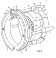
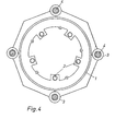
- the fastening part 1 has the shape of a receiving bell, in the front surface of which holes 2 are provided, can be inserted through the screws on the planetary gear housing of the axle, so that the fastening part 1 can be fixed relative to the axle of the vehicle by these screws. No parts of the vehicle are shown in the drawing.
- Linear guides 3 are provided on the fastening part 1.
- a support column 4 is guided in a slide bearing or roller bearing guide that is as free of play as possible.
- the bearing support body 5 is fastened to the ends of the support columns 4.
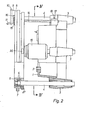
- the roller bearings 6 are mounted on the parts of the ends of the support columns 4 lying in front of them.
- the revolving carrier 7 is rotatably mounted on the latter, which is connected to a ring 27 by a screw connection (not shown in the drawing) and serves to axially secure the position of the revolving carrier 7 on the roller bearings 6.
- the circumferential carrier 7 has the shape of a slewing ring, which has a bracket 8 at one point, to which a guide part 9 is fastened, in which a guide carriage 10 is guided, to which the turning tool 11 is fastened.
- a scale 12 is provided on the guide part 9 and a marking 13 is provided on the guide carriage 10, which enables the guide carriage 10 and thus the turning tool 11 to be set exactly.
- the guide carriage 10 can be precisely fixed in the guide 9 and can be adjusted radially to the axis of rotation of the rotating carrier 7. To enable fine adjustment. can also be provided in the drawing, also not shown, threaded adjustment device.
- a spindle 14 is also rotatably mounted, which is fixedly connected at its left end in the drawing to a drive pulley 15 which has four recesses into which a tooth-like projection 16 on the guide 9 can engage when it passes.
- a housing 17 is also attached, in which a lock nut for the thread of the spindle 14 is mounted, which can be released by pressing the push button 18.
- an electric motor 19 is also mounted, which drives the ring 27 by means of a friction wheel 20, which is connected to the rotating carrier 7, so that the latter is also driven.
- the mode of operation is as follows: After the fastening part 1 by means of screws inserted through the bore 2 attached and aligned, the lock nut is released by pressing the push button 18 so that the spindle 14 can be easily axially displaced. This means that the turning tool 11 can also be easily moved into the position appropriate for the start of the machining process. Then, by releasing the push button 18, the lock nut around the spindle 14 is closed and the electric motor 19 switched on, which now causes the rotating carrier 7 to rotate about the bearing support body 5. The rotary tool 11 rotates together with the rotating carrier 7.
Landscapes
- Engineering & Computer Science (AREA)
- Mechanical Engineering (AREA)
- Turning (AREA)
- Braking Arrangements (AREA)
Applications Claiming Priority (2)
| Application Number | Priority Date | Filing Date | Title |
|---|---|---|---|
| DE3006080 | 1980-02-19 | ||
| DE19803006080 DE3006080C2 (de) | 1980-02-19 | 1980-02-19 | Bremsbelagabdrehmaschine |
Publications (2)
| Publication Number | Publication Date |
|---|---|
| EP0034362A2 true EP0034362A2 (fr) | 1981-08-26 |
| EP0034362A3 EP0034362A3 (fr) | 1983-01-05 |
Family
ID=6094938
Family Applications (1)
| Application Number | Title | Priority Date | Filing Date |
|---|---|---|---|
| EP81101092A Withdrawn EP0034362A3 (fr) | 1980-02-19 | 1981-02-16 | Machine à rectifier les garnitures de frein |
Country Status (7)
| Country | Link |
|---|---|
| EP (1) | EP0034362A3 (fr) |
| JP (1) | JPS56157901A (fr) |
| AU (1) | AU6742081A (fr) |
| DE (1) | DE3006080C2 (fr) |
| DK (1) | DK72081A (fr) |
| ES (1) | ES8201456A1 (fr) |
| PL (1) | PL229761A1 (fr) |
Cited By (2)
| Publication number | Priority date | Publication date | Assignee | Title |
|---|---|---|---|---|
| DE9101397U1 (de) * | 1991-02-07 | 1991-04-25 | GPA Gesellschaft für Prozeß-Automaten GmbH, 2000 Hamburg | Vorrichtung zur Bestimmung der Holzfestigkeit |
| US20160257014A1 (en) * | 2013-10-12 | 2016-09-08 | Battenfeld-Cincinnati Germany Gmbh | Device for cutting extruded plastic profiles to length |
Families Citing this family (1)
| Publication number | Priority date | Publication date | Assignee | Title |
|---|---|---|---|---|
| JPH0572301U (ja) * | 1992-03-13 | 1993-10-05 | 川鉄鉄構工業株式会社 | 固定された軸部材の切削装置 |
Family Cites Families (4)
| Publication number | Priority date | Publication date | Assignee | Title |
|---|---|---|---|---|
| DE2357548A1 (de) * | 1973-11-17 | 1975-05-22 | Werner Dehler | Vorrichtung zum abdrehen von bremsbacken fuer schwerfahrzeuge |
| DE2422587C2 (de) * | 1974-05-09 | 1975-10-02 | Maschinenfabrik Augsburg-Nuernberg Ag, 8000 Muenchen | Vorrichtung zum Abdrehender Bremsbacken in Fahrzeugachsen |
| DE2442789C3 (de) * | 1974-09-06 | 1978-03-09 | Ludwig Hunger Maschinenfabrik Gmbh, 8912 Kaufering | Vorrichtung zum Abdrehen von Bremsbelägen bei Fahrzeugen |
| DE2833929A1 (de) * | 1978-08-02 | 1980-02-21 | Sedelmayer Franz X Jun | Staubschutzeinrichtung fuer bremsbelagabdrehgeraete |
-
1980
- 1980-02-19 DE DE19803006080 patent/DE3006080C2/de not_active Expired
-
1981
- 1981-02-16 ES ES499468A patent/ES8201456A1/es not_active Expired
- 1981-02-16 EP EP81101092A patent/EP0034362A3/fr not_active Withdrawn
- 1981-02-18 AU AU67420/81A patent/AU6742081A/en not_active Abandoned
- 1981-02-18 DK DK72081A patent/DK72081A/da not_active Application Discontinuation
- 1981-02-19 PL PL22976181A patent/PL229761A1/xx unknown
- 1981-02-19 JP JP2235481A patent/JPS56157901A/ja active Pending
Cited By (3)
| Publication number | Priority date | Publication date | Assignee | Title |
|---|---|---|---|---|
| DE9101397U1 (de) * | 1991-02-07 | 1991-04-25 | GPA Gesellschaft für Prozeß-Automaten GmbH, 2000 Hamburg | Vorrichtung zur Bestimmung der Holzfestigkeit |
| US20160257014A1 (en) * | 2013-10-12 | 2016-09-08 | Battenfeld-Cincinnati Germany Gmbh | Device for cutting extruded plastic profiles to length |
| US9914231B2 (en) * | 2013-10-12 | 2018-03-13 | Battenfeld-Cincinnati Germany Gmbh | Device for cutting extruded plastic profiles to length |
Also Published As
| Publication number | Publication date |
|---|---|
| PL229761A1 (fr) | 1981-09-18 |
| AU6742081A (en) | 1981-08-27 |
| EP0034362A3 (fr) | 1983-01-05 |
| DK72081A (da) | 1981-08-20 |
| DE3006080C2 (de) | 1982-09-16 |
| JPS56157901A (en) | 1981-12-05 |
| DE3006080A1 (de) | 1981-08-20 |
| ES499468A0 (es) | 1981-12-01 |
| ES8201456A1 (es) | 1981-12-01 |
Similar Documents
| Publication | Publication Date | Title |
|---|---|---|
| DE2500748C3 (de) | Spindelstock | |
| DE1752834A1 (de) | Antriebseinrichtung fuer das Werkzeugspannfutter einer Werkzeugmaschine | |
| EP0123956A2 (fr) | Rectifieuse cylindrique pour rectification intérieure et extérieure avec commande numérique | |
| CH679841A5 (fr) | ||
| DE1905003A1 (de) | Werkzeugmaschine mit automatischem Werkzeugwechsel | |
| DE2937976C2 (de) | Maschine zum Schleifen oder Fräsen von konvexen und/oder konkaven sphärischen Flächen | |
| DE1920654C3 (de) | Bohr- und Plandrehkopf | |
| DE102012018358A1 (de) | Werkzeuganordnung | |
| DE3822565C2 (fr) | ||
| DE3804502C2 (fr) | ||
| EP0034362A2 (fr) | Machine à rectifier les garnitures de frein | |
| EP0095110B1 (fr) | Dispositif pour la rectification des disques de freins montés sur des véhicules automobiles | |
| DE829398C (de) | Maschine zum Profilieren von Nocken | |
| DE3016262C2 (de) | Vorrichtung zur spanabhebenden Herstellung von kreisförmigen Ausnehmungen o.dgl. in Werkstücken | |
| DE3034788A1 (de) | Universal-schleifmaschine | |
| DE2004715A1 (de) | Drehbare Einspannvorrichtung | |
| DE2328439B2 (de) | Schwenkbarer Werkstück-Aufspanntisch für Werkzeugmaschinen, Insbesondere für Universal-Fräsmaschlnen | |
| DE19715771C1 (de) | Außenräummaschine | |
| DE4234049A1 (de) | Reitstock für eine Drehmaschine | |
| DE3915199C1 (en) | Grinder for vehicle brake discs - incorporates opposed grinding wheels and reciprocating spindles | |
| DE696075C (de) | Maschine zur Bearbeitung der Mantelflaeche von Werkstuecken | |
| DE1914543C (de) | Schwenkbar angeordnete Werkzeug spindel fur eine Handbohrmaschine | |
| DE1214572B (de) | Elektrisch angetriebenes Handwerkzeug zum Polieren von Rohren | |
| DE2442199C3 (de) | Einrichtung an einer Schleifmaschine zum Aufsetzen und Abnehmen des Schleifwerkzeugs | |
| EP0013734A1 (fr) | Dispositif pour l'équilibrage dynamique de corps rotatifs, en particulier de meules |
Legal Events
| Date | Code | Title | Description |
|---|---|---|---|
| PUAI | Public reference made under article 153(3) epc to a published international application that has entered the european phase |
Free format text: ORIGINAL CODE: 0009012 |
|
| AK | Designated contracting states |
Designated state(s): BE DE FR GB IT NL SE |
|
| PUAL | Search report despatched |
Free format text: ORIGINAL CODE: 0009013 |
|
| AK | Designated contracting states |
Designated state(s): BE DE FR GB IT NL SE |
|
| STAA | Information on the status of an ep patent application or granted ep patent |
Free format text: STATUS: THE APPLICATION IS DEEMED TO BE WITHDRAWN |
|
| 18D | Application deemed to be withdrawn |
Effective date: 19831213 |
|
| RIN1 | Information on inventor provided before grant (corrected) |
Inventor name: CZAPIEWSKI, MANFRED Inventor name: SPRENG, KARL |