EP0034404B1 - Reibungskupplungen - Google Patents
Reibungskupplungen Download PDFInfo
- Publication number
- EP0034404B1 EP0034404B1 EP81300189A EP81300189A EP0034404B1 EP 0034404 B1 EP0034404 B1 EP 0034404B1 EP 81300189 A EP81300189 A EP 81300189A EP 81300189 A EP81300189 A EP 81300189A EP 0034404 B1 EP0034404 B1 EP 0034404B1
- Authority
- EP
- European Patent Office
- Prior art keywords
- friction
- interface
- driven
- oil
- passage
- Prior art date
- Legal status (The legal status is an assumption and is not a legal conclusion. Google has not performed a legal analysis and makes no representation as to the accuracy of the status listed.)
- Expired
Links
- 239000012530 fluid Substances 0.000 claims abstract description 20
- 238000001816 cooling Methods 0.000 claims description 6
- 238000005461 lubrication Methods 0.000 claims description 3
- 239000007788 liquid Substances 0.000 description 4
- 238000010276 construction Methods 0.000 description 2
- 230000001050 lubricating effect Effects 0.000 description 2
- 238000000034 method Methods 0.000 description 2
- 229910000831 Steel Inorganic materials 0.000 description 1
- 230000002411 adverse Effects 0.000 description 1
- 230000004888 barrier function Effects 0.000 description 1
- 238000002485 combustion reaction Methods 0.000 description 1
- 239000012809 cooling fluid Substances 0.000 description 1
- 239000000110 cooling liquid Substances 0.000 description 1
- 239000006260 foam Substances 0.000 description 1
- 239000002783 friction material Substances 0.000 description 1
- 238000009434 installation Methods 0.000 description 1
- 239000003595 mist Substances 0.000 description 1
- 238000012986 modification Methods 0.000 description 1
- 230000004048 modification Effects 0.000 description 1
- 238000013021 overheating Methods 0.000 description 1
- 230000021715 photosynthesis, light harvesting Effects 0.000 description 1
- 238000003825 pressing Methods 0.000 description 1
- 239000007787 solid Substances 0.000 description 1
- 239000010959 steel Substances 0.000 description 1
Images


Classifications
-
- F—MECHANICAL ENGINEERING; LIGHTING; HEATING; WEAPONS; BLASTING
- F16—ENGINEERING ELEMENTS AND UNITS; GENERAL MEASURES FOR PRODUCING AND MAINTAINING EFFECTIVE FUNCTIONING OF MACHINES OR INSTALLATIONS; THERMAL INSULATION IN GENERAL
- F16D—COUPLINGS FOR TRANSMITTING ROTATION; CLUTCHES; BRAKES
- F16D13/00—Friction clutches
- F16D13/58—Details
- F16D13/72—Features relating to cooling
-
- F—MECHANICAL ENGINEERING; LIGHTING; HEATING; WEAPONS; BLASTING
- F16—ENGINEERING ELEMENTS AND UNITS; GENERAL MEASURES FOR PRODUCING AND MAINTAINING EFFECTIVE FUNCTIONING OF MACHINES OR INSTALLATIONS; THERMAL INSULATION IN GENERAL
- F16D—COUPLINGS FOR TRANSMITTING ROTATION; CLUTCHES; BRAKES
- F16D13/00—Friction clutches
- F16D13/58—Details
- F16D13/74—Features relating to lubrication
Definitions
- the invention relates to friction clutches of the kind in which a fluid such as oil is used to lubricate and/or cool the inter-engaging friction faces and which are generally known as wet clutches.
- wet friction clutch incorporates a driving member which is normally the engine flywheel and a pressure member which is normally referred to as a pressure plate and which is urged towards the flywheel.
- a driven member normally referred to as a driven plate is arranged between the flywheel and pressure plate.
- These members have inter-engaging friction faces which constitute one friction interface between the flywheel and driven plate and another friction interface between the driven plate and pressure plate. Torque is applied to the driven plate through both friction interfaces.
- a wet clutch oil or a similar fluid is supplied, normally by centrifugal force, to the region of the friction faces of the driven plate and some of this oil finds its way to both the friction interfaces.
- This kind of arrangement for dividing oil flow between two interfaces of a clutch is not suitable for the kind of clutch in which the driven member incorporates a friction facing carrier plate rivetted or similarly secured to a splined hub.
- This kind of driven member is frequently used in single plate clutches intended for installation in a limited axial space and intended for use in situations where a low moment of inertia for the driven member is required.
- the limited space and low inertia requirements preclude the use of the known types of oil distribution system discussed above.
- Another disadvantage of the known oil distribution systems is that they require a high flow rate of oil to fill the reservoir and sufficient speed of the driven member to provide an adequate centrifugal force before even distribution of the oil can be achieved. With many clutches it is particularly important to achieve good oil distribution at low speeds or even when the driven member is stationary and when the rate of oil supply is low.
- a wet clutch system with a single driven plate is disclosed in FR-A-2060897.
- an annular collector plate of dished configuration receives liquid from a feed tube, and at its outer periphery leads the liquid into the general region of the friction linings of the clutch.
- the clutch driven plate has apertures which allow cooling liquid to reach the friction linings of both sides of the driven plate.
- the configuration of the collector plate is such that the liquid leaving it at its outer periphery will have a very large radial component of movement and little axial component, such that very little of the liquid will pass through the openings in the driven plate. Effective and controlled distribution to the friction linings on both sides of the driven plate is not therefore provided.
- a similar arrangement is disclosed in US-A-3964587, with the same disadvantages.
- US-A-3805935 discloses a clutch cooled by a fluid, particularly air, in which the friction plate of the clutch has internal passages for fluid flow.
- the cooling air passes through apertures in the plate to reach the friction surfaces.
- this entails a complex construction of friction plate to achieve fluid distribution.
- An object of the present invention is to provide an improved fluid supply to a wet clutch which overcomes the above mentioned disadvantages.
- a friction clutch comprising a rotary driving member with a friction face on the rotary driving member; a pressure member which is rotatable with the driving member and can be urged towards the driving member by spring means; a friction face on the pressure member; a driven member disposed between the driving and pressure members; friction faces on the driven member for engagement with the friction faces of the driving and pressure members so that the latter members can drive the driven member frictionally through a first interface defined by the friction face of the driving member and one friction face of the driven member and a second interface defined by the friction face of the pressure member and the other friction face of the driven member; and means for supplying fluid to the friction faces of the driven member for cooling and lubrication thereof, fluid from said supply means being flung outward in use by centrifugal force to the friction faces; said means comprising a distribution member connected to said driven member for rotation therewith; a first passage leading outward to one interface; a second passage leading outward to the other interface; characterised in that said distribution number is generally bell
- the invention provides for effective control of distribution of cooling fluid between the two friction faces of the driven member. As described hereafter, it is possible to provide for the fluid to be divided in equal or unequal proportions between the two friction faces.
- the clutch of Figures 1 and 2 incorporates a rotary driving member or flywheel 11 driven by the crank shaft of an internal combustion engine (not shown).
- An annular clutch cover 12 is secured by means of integral legs 13 and bolts 14 to the flywheel 11 so that it rotates with the flywheel about rotational axis 15.
- the clutch cover 12 carries a pressure member in the form of a pressure plate 16 which is arranged to rotate with the cover 12 (and flywheel 11) by means of three lugs 17 (only one is shown) engaging in apertures 18 in the cover.
- Lugs 17 are also connected by means of links 20 to release levers 19 which are pivoted to the cover 12 at 21 and hence serve to control axial movement of the pressure plate 16 with respect to the cover 12 and flywheel 11.
- Several coil springs 22 are arranged around the periphery of the clutch between the cover 12 and pressure plates 16 and serve to urge the pressure plate 16 towards the flywheel 11.
- a driven member constituted by driven plate 23 is arranged between the pressure plate 16 and flywheel 11 and has opposed friction faces which engage with corresponding friction faces on the flywheel 11 and pressure plate 16. These friction faces provide one interface 25 between the driven plate and flywheel and another interface 24 between the driven plate and pressure plate.
- the driven plate (other parts of which will be described in greater detail subsequently) is connected through a splined connection 26 to a shaft 27 which constitutes the output shaft from the clutch and is normally a gearbox input shaft.
- Output shaft 27 is surrounded by a fixed sleeve 28 on which can slide axially a guide 29 carrying a release bearing 31.
- guide 29 is moved axially to operate the release levers 19 in order to move the pressure plate 16 axially.
- springs 22 urge the pressure plate 16 towards the flywheel 11 in order to clamp the driven plate 23 frictionally and establish a driving connection from flywheel 11 through the driven plate to output shaft 27.
- guide 29 is moved towards the release levers 19, it causes the levers to pivot about their pivot 21 and to move pressure plate 16 away from the driven plate 23 against the force of springs 22. This releases the clutch.
- a suitable fluid, normally oil, for lubricating and cooling the friction interfaces 24 and 25 is supplied to a central region of the clutch through a series of grooves 32 between output shaft 27 and sleeve 28.
- This oil is flung out generally radially by centrifugal force together with a flow of air as a mist or foam or series of droplets and finds its way to the friction interfaces 24 and 25 to provide lubrication and cooling.
- the driven plate incorporates a hub member 33 with a central portion 34 splined at 26 to the output shaft 27, three radial spokes 30 and an outer rim 35.
- the hub member 33 is dished so that part of the rim 35 is offset axially from spokes 30 and central portion 34.
- a friction facing carrier plate 36 is riveted at 37 at several locations around its periphery to the outer rim 35.
- Plate 36 carries two friction facings 39 and 38 which engage respectively with the friction faces on the flywheel 11 and pressure plate 16 and thus form the friction interfaces 24 and 25.
- a frusto-conical guide member 41 with a radial flange 42 is riveted by means of this flange and rivets 43 to the outer region of the spokes 30.
- Guide 41 together with the dished part of hub member 33 together form a generally bell shaped distribution member which guides oil leaving the end of sleeve 28 towards the interfaces 24 and 25. Oil escapes from the end of sleeve 28 into a generally rotating environment so that it tends to fly outward by centrifugal force, not only on contact with solid parts of the clutch but also in an air stream which tends to rotate and move outward under centrifugal force.
- the bell shape of the distribution member causes the flow of oil to have an axial component as well as its radial component so that the flow of oil in the distribution member as thus far described is as shown in the lower part of Figure 1.
- the oil flows axially past the interface 24 and more particularly past a passage 44 between the pressure plate 16 and carrier plate 36 which leads to the interface 24. All of this oil is discharged into a passage 45 between the flywheel 11 and carrier plate 36 so that it flows in an outward direction through this passage to the interface 25.
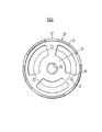
- the outer rim 35 of hub member 33 is provided with a series of six apertures 47 arranged around its periphery and these are best seen from Figure 2. Oil guided by the distribution member and meeting these apertures tends to pass through the apertures and thus into the passage 44 which leads to interface 24. This oil flow is shown in the upper part of Figure 1.
- oil is distributed evenly around the periphery of the components of the clutch at both interfaces rather than being distributed to one interface at one circumferential position and to the other interface at another circumferential position.
- the size of the apertures 47 in relation to the intervening continuous parts of the distribution member controls the proportions in which the oil is distributed between the two interfaces.
- the apertures 47 should be arranged to give equal distribution. This does not necessarily mean that the apertures should cover 50% of the circumference.
- the actual size of aperture 47 required to give . equal oil distribution depends on several factors which are not readily quantifiable. The most convenient procedure is to use trial and error methods with a different number and/or size of apertures.
- the clutch shown in Figure 3 bears some similarity to the clutch of Figures 1 and 2 but incorporates a permanently connected power take off drive and some modification to the oil distribution.
- the clutch incorporates a flywheel 51, a cover 52 which is secured to the flywheel outside the plane of section of Figure 3 in a way similar to that shown in Figure 1, a pressure plate 53 driven from the cover 52 through lugs 54 and urged towards the flywheel 51 by means of springs 55.
- a driven plate 56 is interposed between the flywheel 51 and pressure plate 53 in such a way as to provide a friction interface 57 with pressure plate 53 and a friction interface 58 with flywheel 51.
- the inner part of the driven plate is used in connection with the oil distribution and will be described subsequently.
- a power take off splined hub 59 is driven from the cover 52 by means of a flexible steel diaphragm 61.
- Hub 59 is splined to a power take off sleeve 62 which runs in bearings 63 in a housing 64.
- a main clutch output shaft 65 which is driven from the driven plate in a way to be described, passes through sleeve 62 with a clearance providing an oil supply passage 66. Oil for lubricating and cooling the clutch is supplied under pressure from a connection 67 in the housing 64. As in the previous embodiment, this oil is released into the interior of the clutch from an annular opening 68 at the clutch end of the sleeve 62.
- the driven plate incorporates a splined hub member 69 which at its inner end engages with co-operating splines on the shaft 65 and at its outer end is rivetted to a friction facing carrier 71.
- the friction facing carrier 71 is offset axially from the central part of the hub so that an outer part 72 of the hub forms part of a generally bell shaped oil distribution member.
- the remainder of the distribution member is constituted by a pressing 73 secured to the hub member and extending back beyond the opening 68 to ensure that it catches all oil released from this opening.
- a series of apertures 74 allow some of the oil which is moved in a combined axial and outward direction along the oil distribution member to escape into a passage 75 leading to the interface 57 as indicated by arrows in the top half of Figure 3.
- a conical baffle 76 secured to the power take off drive forms a boundary for part of the passage 75 and ensures that the oil does not escape behind the pressure plate 53.
- the number and size of the apertures 74 should be adjusted to provide the desired division of the oil flow between the two interfaces 57 and 58.
- the fact that openings 57 cannot extend around the whole of the periphery of the hub 69 and so can provide some resistance to oil flow to the passage 78 can also influence the proportion of distribution.
- one factor which can influence the proportions in which oil is distributed is the speed of rotation of the clutch, or more particularly the speed of rotation of the various parts of the clutch because the driven plate may be stationary or rotating at a different speed from that of the flywheel immediately prior to clutch engagement. If the clutch is intended for use at a range of different speeds, the equal distribution should be achieved at a typical speed at which the clutch is normally engaged. In the case of an agricultural tractor for which the present invention is particularly suitable, only a limited range of engine speeds and thus of flywheel and clutch cover speeds is normally used so it is possible to achieve distribution of oil in the required proportions for all speeds used in practice. With an agricultural tractor, the driven plate is normally, but not always stationary during clutch engagement.
- the conditions at the two interfaces differ from each other so that different proportions of the total oil flow are required at each interface. For example if the pressure plate acts as less of a heat sink than the flywheel, more than 50% of the oil may be required at that interface. It is even possible to use different friction materials at the two interfaces, again possibly resulting in different oil requirements.
- both interfaces 24 and 25 can be lubricated and cooled to a desired extent it is possible to operate the clutch close to the upper theoretical limit of factors such as torque, slip speed and total energy dissipation without causing the clutch to deteriorate. These factors contribute to a high performance clutch with a long life.
Landscapes
- Engineering & Computer Science (AREA)
- General Engineering & Computer Science (AREA)
- Mechanical Engineering (AREA)
- Mechanical Operated Clutches (AREA)
- Braking Arrangements (AREA)
- Hydraulic Clutches, Magnetic Clutches, Fluid Clutches, And Fluid Joints (AREA)
- Power Steering Mechanism (AREA)
Claims (3)
Priority Applications (1)
| Application Number | Priority Date | Filing Date | Title |
|---|---|---|---|
| AT81300189T ATE14155T1 (de) | 1980-02-19 | 1981-01-16 | Reibungskupplungen. |
Applications Claiming Priority (2)
| Application Number | Priority Date | Filing Date | Title |
|---|---|---|---|
| GB8005519 | 1980-02-19 | ||
| GB8005519 | 1980-02-19 |
Publications (3)
| Publication Number | Publication Date |
|---|---|
| EP0034404A2 EP0034404A2 (de) | 1981-08-26 |
| EP0034404A3 EP0034404A3 (en) | 1981-10-07 |
| EP0034404B1 true EP0034404B1 (de) | 1985-07-03 |
Family
ID=10511483
Family Applications (1)
| Application Number | Title | Priority Date | Filing Date |
|---|---|---|---|
| EP81300189A Expired EP0034404B1 (de) | 1980-02-19 | 1981-01-16 | Reibungskupplungen |
Country Status (7)
| Country | Link |
|---|---|
| US (1) | US4413716A (de) |
| EP (1) | EP0034404B1 (de) |
| AT (1) | ATE14155T1 (de) |
| BR (1) | BR8100906A (de) |
| DE (1) | DE3171159D1 (de) |
| ES (1) | ES8205967A1 (de) |
| IE (1) | IE50717B1 (de) |
Families Citing this family (13)
| Publication number | Priority date | Publication date | Assignee | Title |
|---|---|---|---|---|
| JPS59131035A (ja) * | 1983-01-14 | 1984-07-27 | Nissan Motor Co Ltd | 湿式クラツチ |
| FR2557232B1 (fr) * | 1983-12-27 | 1989-06-09 | Valeo | Embrayage multidisque dont la lubrification et le refroidissement sont ameliores |
| US5421438A (en) * | 1993-12-14 | 1995-06-06 | Dana Corporation | Clutch having hydrodynamic cooling of pressure plate |
| US7024751B2 (en) | 2003-03-25 | 2006-04-11 | Metaldyne Company Llc | Housing and method of manufacturing said housing |
| DE112007000452A5 (de) * | 2006-04-04 | 2008-11-27 | Luk Lamellen Und Kupplungsbau Beteiligungs Kg | Radiale Stromungskammer für Kupplungen in einer Kupplungsbaugruppe |
| US8074534B2 (en) * | 2007-07-30 | 2011-12-13 | Caterpillar Inc. | Flywheel having lubrication-flow passageway |
| WO2010029573A2 (en) * | 2008-08-11 | 2010-03-18 | Deere & Company | Integrated wet clutch and damper assembly for a transmission and oil management system thereof |
| US9249838B2 (en) * | 2012-03-16 | 2016-02-02 | Gm Global Technology Operations, Llc | Transmission clutch with improved cooling |
| US9163715B2 (en) | 2013-08-23 | 2015-10-20 | American Axle & Manufacturing, Inc. | Clutched power transmitting device with filter element |
| US9353846B2 (en) | 2013-08-23 | 2016-05-31 | American Axle & Manufacturing, Inc. | Power transmitting component with torque transfer device configured with fluid evacuation and lubrication system |
| US9303696B2 (en) | 2013-08-23 | 2016-04-05 | American Axle & Manufacturing, Inc. | Optimized outer clutch housing for reduced spin loss, improved oil flow and improved clutch durability |
| US10830286B2 (en) * | 2018-07-18 | 2020-11-10 | Ford Global Technologies, Llc | Transmission clutch with passive, speed-based fluid distribution |
| US11428274B1 (en) * | 2021-05-18 | 2022-08-30 | Ford Global Technologies, Llc | Vehicle clutch assembly having oil deflector |
Family Cites Families (12)
| Publication number | Priority date | Publication date | Assignee | Title |
|---|---|---|---|---|
| US2498123A (en) * | 1944-07-20 | 1950-02-21 | Hobbs Transmission Ltd | Lubricated friction clutch |
| GB694385A (en) | 1950-03-02 | 1953-07-22 | Gen Motors Corp | Improvements in clutches and clutch plates |
| GB702092A (en) | 1950-10-11 | 1954-01-06 | Fritz Kreis | Improvements in lubricating devices for friction disc clutches |
| FR1367574A (fr) * | 1963-06-08 | 1964-07-24 | Ferodo Sa | Perfectionnements aux transmissions comportant un embrayage |
| GB1101471A (en) | 1966-03-23 | 1968-01-31 | Abex Corp | Friction clutch or brake assembly |
| US3474888A (en) * | 1967-06-26 | 1969-10-28 | Mack Trucks | Lubrication system for wet clutches |
| SE364097B (de) * | 1969-09-05 | 1974-02-11 | Borg Warner | |
| US3610384A (en) * | 1970-06-08 | 1971-10-05 | Borg Warner | Fluid cooled clutch |
| US3760918A (en) | 1972-04-20 | 1973-09-25 | Deere & Co | Tractor pto and propulsion clutch assembly including lubrication means |
| US3805935A (en) * | 1972-06-27 | 1974-04-23 | Lipe Rollway Corp | Impingement cooling means for friction clutch or disc brake |
| JPS5236931Y2 (de) * | 1973-02-24 | 1977-08-23 | ||
| US3964587A (en) * | 1973-08-02 | 1976-06-22 | Borg-Warner Corporation | Control valve for a wet clutch |
-
1981
- 1981-01-16 AT AT81300189T patent/ATE14155T1/de not_active IP Right Cessation
- 1981-01-16 DE DE8181300189T patent/DE3171159D1/de not_active Expired
- 1981-01-16 EP EP81300189A patent/EP0034404B1/de not_active Expired
- 1981-01-29 US US06/229,762 patent/US4413716A/en not_active Expired - Fee Related
- 1981-02-16 BR BR8100906A patent/BR8100906A/pt unknown
- 1981-02-18 IE IE320/81A patent/IE50717B1/en unknown
- 1981-02-18 ES ES499548A patent/ES8205967A1/es not_active Expired
Also Published As
| Publication number | Publication date |
|---|---|
| EP0034404A2 (de) | 1981-08-26 |
| ES499548A0 (es) | 1982-07-01 |
| ATE14155T1 (de) | 1985-07-15 |
| EP0034404A3 (en) | 1981-10-07 |
| BR8100906A (pt) | 1981-08-25 |
| IE810320L (en) | 1981-08-19 |
| US4413716A (en) | 1983-11-08 |
| ES8205967A1 (es) | 1982-07-01 |
| IE50717B1 (en) | 1986-06-25 |
| DE3171159D1 (en) | 1985-08-08 |
Similar Documents
| Publication | Publication Date | Title |
|---|---|---|
| US3249189A (en) | Transmission clutch control and pump drive mechanism | |
| EP0034404B1 (de) | Reibungskupplungen | |
| EP0718519B1 (de) | Nasskupplungseinheit | |
| US3474888A (en) | Lubrication system for wet clutches | |
| US6189669B1 (en) | Multi-disk friction device having forced lubrication on demand | |
| EP0002447B1 (de) | Hydrodynamische Drehmomentenübertragungseinrichtung | |
| EP0987459B1 (de) | Mehrscheiben-Reibeinrichtung mit steuerbarer Zwangsschmierung | |
| US5577581A (en) | Coupling assembly | |
| US9249838B2 (en) | Transmission clutch with improved cooling | |
| US3981381A (en) | Self-contained multiplate wet clutch | |
| KR930011081B1 (ko) | 연속 가변 변속기용 시동 클러치 조립체 | |
| US2659468A (en) | Lubricated friction disk | |
| US11469646B2 (en) | Oil distribution in a hybrid module | |
| US2290542A (en) | Clutch | |
| GB1573328A (en) | Wet cluth mechanism | |
| US10830286B2 (en) | Transmission clutch with passive, speed-based fluid distribution | |
| EP0422767A2 (de) | Hydraulische Hauptkupplung für stufenloses Getriebe | |
| US4023661A (en) | Cooling system for a vehicle clutch | |
| US20240288036A1 (en) | Fluid conducting assembly for a multi-plate clutch and clutch unit | |
| GB2152601A (en) | Clutch with a piloted and spring loaded driven disc hub | |
| JPS5986719A (ja) | 始動クラツチ | |
| US4085835A (en) | Liquid cooled clutches | |
| US4560048A (en) | Cooling system for friction clutches for vehicles | |
| US6237727B1 (en) | Wet type multi-plate friction engaging apparatus | |
| US3734259A (en) | Liquid cooled clutches |
Legal Events
| Date | Code | Title | Description |
|---|---|---|---|
| PUAI | Public reference made under article 153(3) epc to a published international application that has entered the european phase |
Free format text: ORIGINAL CODE: 0009012 |
|
| PUAL | Search report despatched |
Free format text: ORIGINAL CODE: 0009013 |
|
| AK | Designated contracting states |
Designated state(s): AT BE DE FR GB IT LU NL SE |
|
| AK | Designated contracting states |
Designated state(s): AT BE DE FR GB IT LU NL SE |
|
| 17P | Request for examination filed |
Effective date: 19811029 |
|
| ITF | It: translation for a ep patent filed | ||
| GRAA | (expected) grant |
Free format text: ORIGINAL CODE: 0009210 |
|
| AK | Designated contracting states |
Designated state(s): AT BE DE FR GB IT LU NL SE |
|
| REF | Corresponds to: |
Ref document number: 14155 Country of ref document: AT Date of ref document: 19850715 Kind code of ref document: T |
|
| REF | Corresponds to: |
Ref document number: 3171159 Country of ref document: DE Date of ref document: 19850808 |
|
| ET | Fr: translation filed | ||
| PG25 | Lapsed in a contracting state [announced via postgrant information from national office to epo] |
Ref country code: LU Free format text: LAPSE BECAUSE OF NON-PAYMENT OF DUE FEES Effective date: 19860131 |
|
| PLBI | Opposition filed |
Free format text: ORIGINAL CODE: 0009260 |
|
| 26 | Opposition filed |
Opponent name: FICHTEL & SACHS AG Effective date: 19860201 |
|
| NLR1 | Nl: opposition has been filed with the epo |
Opponent name: FICHTEL & SACHS AG |
|
| PGFP | Annual fee paid to national office [announced via postgrant information from national office to epo] |
Ref country code: AT Payment date: 19870114 Year of fee payment: 7 |
|
| PGFP | Annual fee paid to national office [announced via postgrant information from national office to epo] |
Ref country code: NL Payment date: 19870131 Year of fee payment: 7 |
|
| PLBN | Opposition rejected |
Free format text: ORIGINAL CODE: 0009273 |
|
| STAA | Information on the status of an ep patent application or granted ep patent |
Free format text: STATUS: OPPOSITION REJECTED |
|
| 27O | Opposition rejected |
Effective date: 19870718 |
|
| NLR2 | Nl: decision of opposition | ||
| REG | Reference to a national code |
Ref country code: GB Ref legal event code: 732 |
|
| PG25 | Lapsed in a contracting state [announced via postgrant information from national office to epo] |
Ref country code: AT Effective date: 19890116 |
|
| PG25 | Lapsed in a contracting state [announced via postgrant information from national office to epo] |
Ref country code: SE Effective date: 19890117 |
|
| ITTA | It: last paid annual fee | ||
| PG25 | Lapsed in a contracting state [announced via postgrant information from national office to epo] |
Ref country code: BE Effective date: 19890131 |
|
| REG | Reference to a national code |
Ref country code: FR Ref legal event code: TP |
|
| ITPR | It: changes in ownership of a european patent |
Owner name: CESSIONE;LUK LAMELLEN UND KUPPLUNGSBAU GMBH |
|
| BERE | Be: lapsed |
Owner name: LAYCOCK ENGINEERING LTD Effective date: 19890131 |
|
| PG25 | Lapsed in a contracting state [announced via postgrant information from national office to epo] |
Ref country code: NL Effective date: 19890801 |
|
| NLV4 | Nl: lapsed or anulled due to non-payment of the annual fee | ||
| PGFP | Annual fee paid to national office [announced via postgrant information from national office to epo] |
Ref country code: DE Payment date: 19891219 Year of fee payment: 10 |
|
| PGFP | Annual fee paid to national office [announced via postgrant information from national office to epo] |
Ref country code: FR Payment date: 19891229 Year of fee payment: 10 |
|
| PGFP | Annual fee paid to national office [announced via postgrant information from national office to epo] |
Ref country code: GB Payment date: 19900131 Year of fee payment: 10 |
|
| PG25 | Lapsed in a contracting state [announced via postgrant information from national office to epo] |
Ref country code: GB Effective date: 19910116 |
|
| GBPC | Gb: european patent ceased through non-payment of renewal fee | ||
| PG25 | Lapsed in a contracting state [announced via postgrant information from national office to epo] |
Ref country code: FR Effective date: 19910930 |
|
| PG25 | Lapsed in a contracting state [announced via postgrant information from national office to epo] |
Ref country code: DE Effective date: 19911001 |
|
| REG | Reference to a national code |
Ref country code: FR Ref legal event code: ST |
|
| EUG | Se: european patent has lapsed |
Ref document number: 81300189.8 Effective date: 19891204 |