EP0034420A2 - Vorrichtung zum Löschen von Bränden in Leitungssystemen - Google Patents
Vorrichtung zum Löschen von Bränden in Leitungssystemen Download PDFInfo
- Publication number
- EP0034420A2 EP0034420A2 EP81300355A EP81300355A EP0034420A2 EP 0034420 A2 EP0034420 A2 EP 0034420A2 EP 81300355 A EP81300355 A EP 81300355A EP 81300355 A EP81300355 A EP 81300355A EP 0034420 A2 EP0034420 A2 EP 0034420A2
- Authority
- EP
- European Patent Office
- Prior art keywords
- fan
- ducting
- fire
- temperature
- circuit
- Prior art date
- Legal status (The legal status is an assumption and is not a legal conclusion. Google has not performed a legal analysis and makes no representation as to the accuracy of the status listed.)
- Withdrawn
Links
- 238000011144 upstream manufacturing Methods 0.000 claims abstract description 8
- 239000000523 sample Substances 0.000 claims description 8
- 238000000605 extraction Methods 0.000 claims description 4
- 238000001514 detection method Methods 0.000 claims 1
- 230000000007 visual effect Effects 0.000 abstract 1
- 239000004519 grease Substances 0.000 description 5
- 239000003517 fume Substances 0.000 description 3
- 239000000843 powder Substances 0.000 description 3
- 238000010411 cooking Methods 0.000 description 2
- REQPQFUJGGOFQL-UHFFFAOYSA-N dimethylcarbamothioyl n,n-dimethylcarbamodithioate Chemical compound CN(C)C(=S)SC(=S)N(C)C REQPQFUJGGOFQL-UHFFFAOYSA-N 0.000 description 2
- 239000000126 substance Substances 0.000 description 2
- ZAMOUSCENKQFHK-UHFFFAOYSA-N Chlorine atom Chemical compound [Cl] ZAMOUSCENKQFHK-UHFFFAOYSA-N 0.000 description 1
- 229920000742 Cotton Polymers 0.000 description 1
- PXGOKWXKJXAPGV-UHFFFAOYSA-N Fluorine Chemical compound FF PXGOKWXKJXAPGV-UHFFFAOYSA-N 0.000 description 1
- GDTBXPJZTBHREO-UHFFFAOYSA-N bromine Substances BrBr GDTBXPJZTBHREO-UHFFFAOYSA-N 0.000 description 1
- 229910052794 bromium Inorganic materials 0.000 description 1
- 229910052801 chlorine Inorganic materials 0.000 description 1
- 239000000460 chlorine Substances 0.000 description 1
- 239000000428 dust Substances 0.000 description 1
- 230000000694 effects Effects 0.000 description 1
- 229910052731 fluorine Inorganic materials 0.000 description 1
- 239000011737 fluorine Substances 0.000 description 1
- 239000006260 foam Substances 0.000 description 1
- 239000007789 gas Substances 0.000 description 1
- 229910052736 halogen Inorganic materials 0.000 description 1
- 150000002367 halogens Chemical class 0.000 description 1
- 229930195733 hydrocarbon Natural products 0.000 description 1
- 150000002430 hydrocarbons Chemical class 0.000 description 1
- 239000000976 ink Substances 0.000 description 1
- 239000000463 material Substances 0.000 description 1
- 239000000203 mixture Substances 0.000 description 1
- 230000007935 neutral effect Effects 0.000 description 1
- 230000009972 noncorrosive effect Effects 0.000 description 1
- 230000001473 noxious effect Effects 0.000 description 1
- 239000003973 paint Substances 0.000 description 1
- 102000004169 proteins and genes Human genes 0.000 description 1
- 108090000623 proteins and genes Proteins 0.000 description 1
- 238000009877 rendering Methods 0.000 description 1
- 239000000779 smoke Substances 0.000 description 1
- 239000007858 starting material Substances 0.000 description 1
- 230000001988 toxicity Effects 0.000 description 1
- 231100000419 toxicity Toxicity 0.000 description 1
- 230000001960 triggered effect Effects 0.000 description 1
- 210000002268 wool Anatomy 0.000 description 1
Images

Classifications
-
- A—HUMAN NECESSITIES
- A62—LIFE-SAVING; FIRE-FIGHTING
- A62C—FIRE-FIGHTING
- A62C3/00—Fire prevention, containment or extinguishing specially adapted for particular objects or places
- A62C3/04—Fire prevention, containment or extinguishing specially adapted for particular objects or places for dust or loosely-baled or loosely-piled materials, e.g. in silos, in chimneys
-
- F—MECHANICAL ENGINEERING; LIGHTING; HEATING; WEAPONS; BLASTING
- F24—HEATING; RANGES; VENTILATING
- F24C—DOMESTIC STOVES OR RANGES ; DETAILS OF DOMESTIC STOVES OR RANGES, OF GENERAL APPLICATION
- F24C15/00—Details
- F24C15/20—Removing cooking fumes
- F24C15/2021—Arrangement or mounting of control or safety systems
-
- A—HUMAN NECESSITIES
- A62—LIFE-SAVING; FIRE-FIGHTING
- A62C—FIRE-FIGHTING
- A62C3/00—Fire prevention, containment or extinguishing specially adapted for particular objects or places
- A62C3/006—Fire prevention, containment or extinguishing specially adapted for particular objects or places for kitchens or stoves
Definitions
- This invention relates to fire extinguishing apparatus for ducting, in particular so called grease ducts used in catering establishments and other situations where inflammable or potentially inflammable materials are extracted.
- These ducts constitute a hazard since if a fire starts in the ducting it can spread rapidly to other parts of the building.
- the problem is particularly severe in ducts leading from grills and griddles because the flames are often generated during cooking. Once the fire has started it is difficult immediately to detect and extinguish.
- fire extinguishing apparatus for ducting incorporating an extractor fan and comprising a fire extinguisher having a discharge head disposed within the ducting upstream of the extraction fan and a heat sensitive valve means operable to release the fire extinguishing medium into the duct at a predetermined temperature, and a temperature sensing unit operatively connected to a circuit selector control for cutting out the fan when the unit detects a pre-set temperature less preferably by at least 90°F, than the predetermined operating temperature of the first extinguisher and including a by-pass circuit whereby the fan can be restarted following discharge of the fire extinguisher.
- the state of the selector control circuit is displayed by an indicator light or lights and optionally an audible alarm.
- the tempature sensing unit is disposed upstream from the fire extinguisher by no more than 3 metres and, further, comprises thermal probe extending into the interior of the ducting.
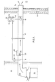
- FIG. 1 is a schematic view of the fire extinguishing apparatus installed in a grease duct leading from a kitchen 10 to the exterior wall 12 of a building.
- an extractor fan 16 is mounted within the ducting 18 to draw air therethrough from an inlet head 20 disposed above a cooking range 22 in the kitchen.
- the entire extinguisher may be mounted within the duct in which case the size and shape of the extinguisher casing are such as to offer minimum resistance to the flow of air through the duct.
- the extinguishing medium may be either a liquefied halogen gas mixture (e.g. BTM or BCF - Bromine, Chlorine, Fluorine) or MONEX (Registered Trade Mark) powder, both of which are internationally recognised and approved or, indeed, any suitable fire extinguishant.
- BCF has the secondary advantage that it is of verylow toxicity, is pure, non-corrosive, and remains effective however long it is stored. Further, it leaves little mess or trace.
- Monex powder is superior to other powders: it does not compact on storage and is compatible with protein foam.
- a heat sensitive valve which is operable at a desired temperature to allowing the extinguishing medium to escape, under pressure, into the duct.
- a temperature sensing unit 30 Upstream of the fire extinguisher and preferably spaced from the extinguisher by no more than 3.metres,.is a temperature sensing unit 30 which is mounted on the exterior of the ducting and has a probe 31, typically 10 cm to 30 cm in length, projecting radially inwards.
- the unit 30 incorporates heat sensitive mechanism e.g. a bimetallic strip which distorts when heated until, at a pre-set temperature of at least 50 0 C less than the temperature setting of the extinguisher, an electrical switch is operated to actuate a circuit selector control 32 connected to the fan starter 35.
- the circuit selector control 32 comprises a three position switch and two indicator lights; one red 33 and the other green 34.
- the fan In one position of the switch corresponding to the normal operating stage, the fan is working and the green indicator light 34 is lit. When the probe operates upon reaching the pre-set temperature, the fan is cut out. When a fire has been extinguished the switch can be.passed through a neutral position to a third position in which a by-pass circuit is completed enabling the fan to be restarted.
- the temperature sensing unit 30 actuates the fan cut-out switch at the lower temperature determined by the setting of the unit that is to say before (by a few seconds) the fire extinguisher is triggered by the heat sensitive valve, hence, the extraction system is. inoperative during discharge of the fire extinguisher and so the ducting fills with fumes, but the fumes can be cleared after the fire has been extinguished, since the selector control circuit can be used to by-pass the fan cut-out switch and the fan may be restarted.
- the circuit selector control 32 comprises a two-position switch with an audible alarm 37 and only one indicator light 38 which is not-illuminated in the normal operating state.
- the control activates the red light, sounds the alarm and automatically stops the fan.
- a control circuit for the modified embodiment is shown in Figure 2 in the normal operating mode with both the light and the alarm off.
- L 1 , L 2 and L 3 are the mains supply to the contractor coil and A,B and C are outgoing connections to the fan motor.
- the mains supply L 3 is connected to L on the heat probe 31 and in the normal operating mode, L is connected to L R which is connected to 1, which is connected to 6, which is connected to L 1 at the fan coil.
- the current path is L3,L,BC,3,2,5,buzzer,Ll and from BC to the light. so that both the buzzer and the light are on.
- the key switch on the control box is turned to override the cut-out mode and the current path is now L 3 ,L,BC,3,6, L 1 and from BC to the light, so that the buzzer is off but the light is still on.
- the apparatus of the present invention is not restricted to grease ducts. Indeed it is suitable for any duct extraction system which conveys volatile or inflammable substances such as hydro-carbons or other chemicals, sawdust, wool, cotton, paint, ink and dust.
Landscapes
- Engineering & Computer Science (AREA)
- Health & Medical Sciences (AREA)
- Public Health (AREA)
- Business, Economics & Management (AREA)
- Emergency Management (AREA)
- Chemical & Material Sciences (AREA)
- Combustion & Propulsion (AREA)
- Mechanical Engineering (AREA)
- General Engineering & Computer Science (AREA)
- Control Of Positive-Displacement Air Blowers (AREA)
- Fire-Extinguishing By Fire Departments, And Fire-Extinguishing Equipment And Control Thereof (AREA)
- Fire Alarms (AREA)
Applications Claiming Priority (2)
| Application Number | Priority Date | Filing Date | Title |
|---|---|---|---|
| GB8002918 | 1980-01-29 | ||
| GB8002918 | 1980-01-29 |
Publications (2)
| Publication Number | Publication Date |
|---|---|
| EP0034420A2 true EP0034420A2 (de) | 1981-08-26 |
| EP0034420A3 EP0034420A3 (de) | 1981-12-23 |
Family
ID=10510961
Family Applications (1)
| Application Number | Title | Priority Date | Filing Date |
|---|---|---|---|
| EP81300355A Withdrawn EP0034420A3 (de) | 1980-01-29 | 1981-01-27 | Vorrichtung zum Löschen von Bränden in Leitungssystemen |
Country Status (5)
| Country | Link |
|---|---|
| EP (1) | EP0034420A3 (de) |
| ES (1) | ES8203621A1 (de) |
| GB (1) | GB2069836B (de) |
| IE (1) | IE50887B1 (de) |
| PT (1) | PT72416B (de) |
Cited By (4)
| Publication number | Priority date | Publication date | Assignee | Title |
|---|---|---|---|---|
| EP1570881A3 (de) * | 2004-03-04 | 2007-07-18 | PAS Engineering GmbH & Co.KG | Einrichtung und Verfahren zur Verminderung und/oder zur Vermeidung einer Rauch- und/oder Brandausbreitung in einem Kanal |
| WO2007097715A1 (en) * | 2006-02-21 | 2007-08-30 | Kim Lui So | Controls for ventilation and exhaust ducts and fans |
| CN107366635A (zh) * | 2017-08-31 | 2017-11-21 | 江西拓宇实业有限公司 | 一种负压排气系统及其控制方法 |
| CN108800249A (zh) * | 2018-06-21 | 2018-11-13 | 佛山市煜升电子有限公司 | 智能抽油烟机 |
Families Citing this family (4)
| Publication number | Priority date | Publication date | Assignee | Title |
|---|---|---|---|---|
| FI932135A0 (fi) * | 1993-05-11 | 1993-05-11 | Goeran Sundholm | Foerfarande och anlaeggning foer brandbekaempning |
| CN102913969B (zh) * | 2012-09-27 | 2015-06-24 | 杭州九龙厨具制造有限公司 | 厨房排烟系统及其灭火方法 |
| WO2019202173A1 (es) * | 2018-04-16 | 2019-10-24 | Soriano Azorin Juan Jose | Equipo extintor recargable y transportable |
| CN112569501B (zh) * | 2021-01-13 | 2021-11-12 | 德清县德创智能技术有限公司 | 一种免检汽车灭火器 |
Family Cites Families (8)
| Publication number | Priority date | Publication date | Assignee | Title |
|---|---|---|---|---|
| US2813477A (en) * | 1954-03-16 | 1957-11-19 | Asa K Gaylord | Safety ventilator unit |
| US3283827A (en) * | 1964-12-08 | 1966-11-08 | Specialties Dev Corp | Hood and duct fire extinguishing system |
| US3433146A (en) * | 1966-10-08 | 1969-03-18 | Kenneth Sinclair Russell | Grease extracting ventilating apparatus |
| US3448808A (en) * | 1967-03-21 | 1969-06-10 | Kidde & Co Walter | Fire extinguishing system and control apparatus |
| US3463233A (en) * | 1967-05-15 | 1969-08-26 | Norris Industries | Method of extinguishing deep fat fires |
| US3517746A (en) * | 1968-04-24 | 1970-06-30 | Gen Fire Extinguisher Corp | Dry chemical fire extinguishing system |
| US3653443A (en) * | 1970-09-25 | 1972-04-04 | Walter E Dockery | Fire extinguishing system for cook stoves and ranges |
| US3770061A (en) * | 1971-11-03 | 1973-11-06 | T Hall | Air scrubber apparatus with improved fire extinguishing means |
-
1981
- 1981-01-27 EP EP81300355A patent/EP0034420A3/de not_active Withdrawn
- 1981-01-27 GB GB8102428A patent/GB2069836B/en not_active Expired
- 1981-01-28 PT PT72416A patent/PT72416B/pt unknown
- 1981-01-28 ES ES498897A patent/ES8203621A1/es not_active Expired
- 1981-01-29 IE IE173/81A patent/IE50887B1/en unknown
Cited By (7)
| Publication number | Priority date | Publication date | Assignee | Title |
|---|---|---|---|---|
| EP1570881A3 (de) * | 2004-03-04 | 2007-07-18 | PAS Engineering GmbH & Co.KG | Einrichtung und Verfahren zur Verminderung und/oder zur Vermeidung einer Rauch- und/oder Brandausbreitung in einem Kanal |
| WO2007097715A1 (en) * | 2006-02-21 | 2007-08-30 | Kim Lui So | Controls for ventilation and exhaust ducts and fans |
| AU2007218220B2 (en) * | 2006-02-21 | 2012-06-28 | Kim Lui So | Controls for ventilation and exhaust ducts and fans |
| CN101443595B (zh) * | 2006-02-21 | 2012-10-10 | 苏剑蕾 | 通风、排气管道以及风扇的控制装置 |
| CN107366635A (zh) * | 2017-08-31 | 2017-11-21 | 江西拓宇实业有限公司 | 一种负压排气系统及其控制方法 |
| CN107366635B (zh) * | 2017-08-31 | 2019-08-27 | 江西拓宇实业有限公司 | 一种负压排气系统及其控制方法 |
| CN108800249A (zh) * | 2018-06-21 | 2018-11-13 | 佛山市煜升电子有限公司 | 智能抽油烟机 |
Also Published As
| Publication number | Publication date |
|---|---|
| ES498897A0 (es) | 1982-04-16 |
| IE810173L (en) | 1981-07-29 |
| PT72416A (en) | 1981-02-01 |
| EP0034420A3 (de) | 1981-12-23 |
| GB2069836A (en) | 1981-09-03 |
| PT72416B (en) | 1982-01-05 |
| GB2069836B (en) | 1984-06-13 |
| ES8203621A1 (es) | 1982-04-16 |
| IE50887B1 (en) | 1986-08-06 |
Similar Documents
| Publication | Publication Date | Title |
|---|---|---|
| US4830116A (en) | Fire extinguishing system | |
| US3653443A (en) | Fire extinguishing system for cook stoves and ranges | |
| US5351760A (en) | Fire suppression system and method for its use | |
| US6655047B2 (en) | Fire arrester for use with a clothes dryer | |
| US4356870A (en) | Water spray fire protection for hoods over cooking units | |
| US6029751A (en) | Automatic fire suppression apparatus and method | |
| US3866687A (en) | Automatic fire extinguisher means | |
| US8651014B2 (en) | Fire containment system | |
| US7182143B2 (en) | Automatic appliance fire extinguisher system | |
| US20090321093A1 (en) | Home kitchen fire suppression system | |
| EP0034420A2 (de) | Vorrichtung zum Löschen von Bränden in Leitungssystemen | |
| US20170266473A1 (en) | Fire extinguishing system for stove tops | |
| KR20130098791A (ko) | 주방용 자동소화장치의 환기 제어 시스템 및 그 방법 | |
| KR101363837B1 (ko) | 자동식 소화장치의 후드 제어 시스템 및 그 방법 | |
| JP3113206B2 (ja) | 自動消火設備における故障発生表示方式 | |
| US20020189824A1 (en) | System for fire extinguishing | |
| GB2149658A (en) | Fire extinguishing systems | |
| JP3532799B2 (ja) | ガス系消火設備における消火ガスの放出制御システム | |
| WO2024091568A1 (en) | Fire suppression device and method of use thereof | |
| JP7334926B2 (ja) | ポンプ装置、制御盤及び制御基板 | |
| US12478813B1 (en) | Automated kitchen hood fire trap | |
| WO2007051240A1 (en) | Automated fire extinguishing system | |
| JP2006212205A (ja) | ガス機器及びその消火システム | |
| JP2001104506A (ja) | 家庭用セントラル消火システム | |
| US3162846A (en) | Smoke and heat operated electrical alarm device |
Legal Events
| Date | Code | Title | Description |
|---|---|---|---|
| PUAI | Public reference made under article 153(3) epc to a published international application that has entered the european phase |
Free format text: ORIGINAL CODE: 0009012 |
|
| AK | Designated contracting states |
Designated state(s): AT BE CH DE FR GB IT LU NL SE |
|
| PUAL | Search report despatched |
Free format text: ORIGINAL CODE: 0009013 |
|
| AK | Designated contracting states |
Designated state(s): AT BE CH DE FR GB IT LU NL SE |
|
| STAA | Information on the status of an ep patent application or granted ep patent |
Free format text: STATUS: THE APPLICATION IS DEEMED TO BE WITHDRAWN |
|
| 18D | Application deemed to be withdrawn |
Effective date: 19821202 |