EP0034528A1 - Spanndorne - Google Patents
Spanndorne Download PDFInfo
- Publication number
- EP0034528A1 EP0034528A1 EP81400203A EP81400203A EP0034528A1 EP 0034528 A1 EP0034528 A1 EP 0034528A1 EP 81400203 A EP81400203 A EP 81400203A EP 81400203 A EP81400203 A EP 81400203A EP 0034528 A1 EP0034528 A1 EP 0034528A1
- Authority
- EP
- European Patent Office
- Prior art keywords
- mandrel
- slide
- workpiece
- loosening
- counterweight
- Prior art date
- Legal status (The legal status is an assumption and is not a legal conclusion. Google has not performed a legal analysis and makes no representation as to the accuracy of the status listed.)
- Granted
Links
- 238000006073 displacement reaction Methods 0.000 claims abstract description 6
- 238000013459 approach Methods 0.000 claims abstract description 4
- 230000033001 locomotion Effects 0.000 claims description 9
- 230000005540 biological transmission Effects 0.000 claims description 8
- 230000000694 effects Effects 0.000 claims description 8
- 230000001815 facial effect Effects 0.000 claims description 4
- 230000000630 rising effect Effects 0.000 claims description 4
- 230000000717 retained effect Effects 0.000 claims description 3
- 238000003754 machining Methods 0.000 abstract description 2
- 230000000977 initiatory effect Effects 0.000 abstract 1
- 238000010276 construction Methods 0.000 description 1
- 238000009434 installation Methods 0.000 description 1
- 238000012986 modification Methods 0.000 description 1
- 230000004048 modification Effects 0.000 description 1
- 230000002093 peripheral effect Effects 0.000 description 1
Images

Classifications
-
- B—PERFORMING OPERATIONS; TRANSPORTING
- B23—MACHINE TOOLS; METAL-WORKING NOT OTHERWISE PROVIDED FOR
- B23B—TURNING; BORING
- B23B31/00—Chucks; Expansion mandrels; Adaptations thereof for remote control
- B23B31/40—Expansion mandrels
- B23B31/404—Gripping the work or tool by jaws moving radially controlled by conical surfaces
- B23B31/4066—Gripping the work or tool by jaws moving radially controlled by conical surfaces using mechanical transmission through the spindle
-
- Y—GENERAL TAGGING OF NEW TECHNOLOGICAL DEVELOPMENTS; GENERAL TAGGING OF CROSS-SECTIONAL TECHNOLOGIES SPANNING OVER SEVERAL SECTIONS OF THE IPC; TECHNICAL SUBJECTS COVERED BY FORMER USPC CROSS-REFERENCE ART COLLECTIONS [XRACs] AND DIGESTS
- Y10—TECHNICAL SUBJECTS COVERED BY FORMER USPC
- Y10T—TECHNICAL SUBJECTS COVERED BY FORMER US CLASSIFICATION
- Y10T279/00—Chucks or sockets
- Y10T279/10—Expanding
- Y10T279/1021—Fluid-pressure actuator
- Y10T279/1033—Expanding jaws via mechanical connection
-
- Y—GENERAL TAGGING OF NEW TECHNOLOGICAL DEVELOPMENTS; GENERAL TAGGING OF CROSS-SECTIONAL TECHNOLOGIES SPANNING OVER SEVERAL SECTIONS OF THE IPC; TECHNICAL SUBJECTS COVERED BY FORMER USPC CROSS-REFERENCE ART COLLECTIONS [XRACs] AND DIGESTS
- Y10—TECHNICAL SUBJECTS COVERED BY FORMER USPC
- Y10T—TECHNICAL SUBJECTS COVERED BY FORMER US CLASSIFICATION
- Y10T279/00—Chucks or sockets
- Y10T279/10—Expanding
- Y10T279/1037—Axially moving actuator
- Y10T279/1041—Wedge
-
- Y—GENERAL TAGGING OF NEW TECHNOLOGICAL DEVELOPMENTS; GENERAL TAGGING OF CROSS-SECTIONAL TECHNOLOGIES SPANNING OVER SEVERAL SECTIONS OF THE IPC; TECHNICAL SUBJECTS COVERED BY FORMER USPC CROSS-REFERENCE ART COLLECTIONS [XRACs] AND DIGESTS
- Y10—TECHNICAL SUBJECTS COVERED BY FORMER USPC
- Y10T—TECHNICAL SUBJECTS COVERED BY FORMER US CLASSIFICATION
- Y10T279/00—Chucks or sockets
- Y10T279/24—Chucks or sockets by centrifugal force
-
- Y—GENERAL TAGGING OF NEW TECHNOLOGICAL DEVELOPMENTS; GENERAL TAGGING OF CROSS-SECTIONAL TECHNOLOGIES SPANNING OVER SEVERAL SECTIONS OF THE IPC; TECHNICAL SUBJECTS COVERED BY FORMER USPC CROSS-REFERENCE ART COLLECTIONS [XRACs] AND DIGESTS
- Y10—TECHNICAL SUBJECTS COVERED BY FORMER USPC
- Y10T—TECHNICAL SUBJECTS COVERED BY FORMER US CLASSIFICATION
- Y10T82/00—Turning
- Y10T82/26—Work driver
- Y10T82/266—Mandrel
- Y10T82/268—Expansible
Definitions
- the present invention relates to an expandable mandrel in which the loading and unloading of the workpiece takes place during the rotation of the mandrel.
- the object of the present invention is to remedy this drawback and to create a mandrel having a positive loosening system consisting in using centrifugal force to effect the withdrawal of the sliders in slots provided in the body of the mandrel to allow the ejection of the workpiece and loading of a new workpiece.
- the mandrel is distinguished in that at the front of the mandrel the workpiece is successively centered and clamped between the lateral face of a radial projection of each of at least two slides and a fixed stop ( or forming an integral part) on (the) chuck fixing plate on the machine tool, said slides being arranged in slots made in the chuck body so as to be able to move radially relative to the longitudinal axis of the chuck , the centering and clamping action of the part P to be machined being controlled by a piston provided with a conical part (or ramps) at its end mite which is in contact with corresponding conical surfaces of said slides; this piston being pushed towards the rear of the mandrel by the action of a first spring after being released by the tightening and loosening control rod of said workpiece, the final tightening of this part being carried out by said rod after that the latter has traveled a distance equal to a radial centering stroke to retreat a distance equal to a facial tighten
- a first ramp arranged in a recess made in the front part of the counterweight and having a slope rising towards the rear cooperates with the rear end of a movement transmission member the other end of which cooperates with a second ramp arranged in a recess made in the rear part of each corresponding slide, and having a slope rising towards the front of so that each slide is brought closer to the longitudinal axis of the mandrel when each corresponding counterweight moves away from the longitudinal axis of the mandrel.
- said movement transmission member is an axis whose ends are frustoconical parts of a length such that each slide is retained in its lumen during total loosening of the workpiece.
- said transmission member can be produced in the form of a series or a chain of adjacent balls.
- the mandrel according to the invention is, moreover, remarkable in that said ramp, in each counterweight, and / or said ramp, in each slide, are the surface of a conical recess formed in said counterweight and / or said slide and that the weight of each counterweight is greater than that of the corresponding slide.
- a safety clearance is provided between the body of the mandrel and the plate which can be absorbed when the mandrel is not loaded with a workpiece.
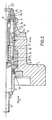
- Figure 1 is a longitudinal section of an embodiment, given by way of example, of the mandrel according to the invention in the clamping position of the workpiece;
- Figure 2 is a longitudinal section of the mandrel of Figure 1 in the released position of the workpiece.
- the mandrel comprises a plate 1 fixed to the machine tool by screws or bolts 2.
- a stop 3 is screwed onto the front part of the plate 1 by screws 4.
- a tie rod 5 disposed at the rear of the mandrel is actuated in the direction of arrow fs to clamp a workpiece P and in the direction f d to loosen this workpiece.
- the mode of actuation of this tie rod 5 can be manual, hydraulic, pneumatic, electro-mechanical or mechanical.
- the tie rod 5 is guided in a part 6 fixed on the plate 1 by screws 7.
- a circular recess 11 is provided in this part 6 to accommodate a spring 12 which bears at the rear on the face of the recess 11 and at the front on a ring 9 fixed to the mandrel body 8 by screws 10.
- a clearance c between the ring 9 and the guide piece 6. This clearance c is a safety game for the case where the mandrel rotates without being loaded with a part 7.
- the tie rod 5, at its front part, is provided with a recess 5 2 ; at its front end, the wall of this recess 5 2 is produced in the form of a flanged rim 51, the rear face of which rests on the ring 9, thus allowing the body of the mandrel to move in the direction of the arrow f s , when clamping the workpiece P.
- the body 8 of the mandrel is stepped; in the clamping position of the part P, a set of facial loosening a remains between the body 8 and the plate 1.
- the body 8 is bored over its entire length. It is further provided with lights 18 for weights 17, and at the front other lights for slides 14.
- the weights and slides can move radially in these lights; they move longitudinally at the same time as the body 8 when the latter is requested in tightening - arrow f s -or in loosening - arrow f d -.
- a clamping control piston 13 can move in the direction of the arrow fd, upon loosening, by the action of the tie rod 5, the rear face of the recess 52 rests on the rear of the piston 13 after having absorbed a radial centering clearance b.
- the piston 13 can move in the direction of arrow f under the action of a spring 19 which bears at the front on a ring 21 placed on the rear of a stepped part of the bore of the body 8 and at the rear on a stop ring 22 retained on the piston by a rod 20.
- the stop ring 22 is in contact by its peripheral surface with the internal surface of the recess 5 2 of the tie rod 5 and can therefore be displaced by relative to the latter under the action of said spring 19.
- the slots 18 provided for the flyweights 17 have the length of the latter so that, in the body 8, the flyweights can only move radially. In the clamping position, there remains a clearance e l between the counterweight 17 and the plate 1.
- a conical recess 17 2 is made , the top of which is at the rear; the conical slope 17 is calculated so as to obtain a low friction between the surface of the conical slope 17 1 and the frusto-conical end 16 1 of an axis 16 for returning the slides 14, as will be explained below.
- the slope of the end 16 1 is equal to the slope 171 of the recess 172.
- the slope 17 1 is arranged in the counterweight so that the axis 16 can bring the sliders 14 closer to the longitudinal axis of the mandrel when the weights 17 swing away from the longitudinal axis of the mandrel under the effect of centrifugal force (due to the permanent rotation of the mandrel).
- the axis 16 is the main shaman of the mechanical chain between the weights 17 and the sliders 14.
- the sliders 14 have a length equal to that of the lights made in the body 8 so as to be unable to carry out, relative to the body 8, than radial displacements.
- the lower part 14 1 of the slides 14 is inclined to cooperate with the conical part 13 1 of the piston 13, that is to say slide relative to the latter, during tightening and loosening of the workpieces P.
- L ' front end 16 2 of axis 16 is also produced in frustoconical form. The slope of this end 16 2 can be the same as that of the end 16 1 of the axis 16.
- a a conical recess 15 is provided in the rear part of the slide 14; the slope 15 1 of the surface of this recess 15 is the same as that of the end 16 2 of the axis 16.
- the slope and the arrangement of the cone are calculated so as to allow a relative longitudinal displacement with low friction between l end 14 1 and the face of the recess 15.
- the slides 14 are at their front parts provided with projections 14 1 of a height equal to a distance e. This distance e is smaller than the distance e 1 above.
- the part P to be machined is clamped between the rear face of these projections 14 1 and the lateral face of the stop 3.
- each frustoconical part 16 1 , 16 2 of the axis 16 is equal to a distance x.
- each flyweight is greater than that of the corresponding slide and can, for example, be substantially double that of the slide.
- the sliders 14 approach the longitudinal axis of the mandrel until the projections 14 1 do not extend beyond the body 8 thus allowing the ejection of the part P by a jet of compressed air, for example which is supplied from the rear of the mandrel through grooves made in the bore of the plate 1 and of the stop 3 along the body 8 of the mandrel (not shown in the drawings).
- a jet of compressed air for example which is supplied from the rear of the mandrel through grooves made in the bore of the plate 1 and of the stop 3 along the body 8 of the mandrel (not shown in the drawings).
- a cover 22 closes at the front the bore of the body 8 of the mandrel.
- the tie rod 5 advances in the direction of the arrow f d and releases the mandrel body 8.
- the latter advances under the action of the spring 12 by absorbing the play a.
- the front part 8 1 of the body 8 has advanced a distance equal to the clearance a, as well as the slides 14.
- the tie rod 5 continues its movement in the direction of the arrow f d .
- the tie rod presses on the rear end of the piston 13.
- the latter also advances in the direction of the arrow f d and drives, via the spring 19, the mandrel body 8 ; the counterweights 17, the axes 16 and the slides 14.
- the counterweights 17, in the openings made in the body 8 move radially away from the longitudinal axis of the mandrel; play a l is reduced.
- the frustoconical ends 16 rear of the axes 16 slide along the slopes 17 1 of the recesses 17 2 of the counterweights 17 in the direction of the arrow f d (that is to say to the right in the figure) over a necessarily shorter distance at distance x.
- Clamping of part P The machined part P is ejected, a new part P is mounted on the front of the mandrel (see figure 2).
- the tie rod 5 moves in the direction of the arrow f s (to the left in the figure) as well as the clamping control piston 13 and the slides 14.
- the axes 16 are pushed to the left (in the figure) by the slides 14 and bring the weights closer to the longitudinal axis of the mandrel by a distance equal to e; centering of the workpiece P to be machined is then achieved by the action of the piston 13 and the slides 14.
- the centering force exerted by the slides is a function of the slope 13 1 of the slope 13 1 of the conical part of the piston 13 and the force of the spring 19.
Landscapes
- Engineering & Computer Science (AREA)
- Mechanical Engineering (AREA)
- Gripping On Spindles (AREA)
Applications Claiming Priority (2)
| Application Number | Priority Date | Filing Date | Title |
|---|---|---|---|
| FR8003548 | 1980-02-19 | ||
| FR8003548A FR2475956A1 (fr) | 1980-02-19 | 1980-02-19 | Mandrin expansible |
Publications (2)
| Publication Number | Publication Date |
|---|---|
| EP0034528A1 true EP0034528A1 (de) | 1981-08-26 |
| EP0034528B1 EP0034528B1 (de) | 1984-05-09 |
Family
ID=9238703
Family Applications (1)
| Application Number | Title | Priority Date | Filing Date |
|---|---|---|---|
| EP81400203A Expired EP0034528B1 (de) | 1980-02-19 | 1981-02-10 | Spanndorne |
Country Status (5)
| Country | Link |
|---|---|
| US (1) | US4373411A (de) |
| EP (1) | EP0034528B1 (de) |
| JP (1) | JPS56157908A (de) |
| DE (1) | DE3163441D1 (de) |
| FR (1) | FR2475956A1 (de) |
Families Citing this family (7)
| Publication number | Priority date | Publication date | Assignee | Title |
|---|---|---|---|---|
| US5868400A (en) * | 1997-02-13 | 1999-02-09 | Lares Research | Push type expanding mandrel apparatus |
| US6739600B1 (en) | 2000-08-15 | 2004-05-25 | Spicer Technology, Inc. | Expanding sleeve fixture |
| US6514017B2 (en) | 2001-03-02 | 2003-02-04 | Deblasio Michael J. | Core drill piloting system |
| US6883407B2 (en) * | 2002-08-30 | 2005-04-26 | Hardinge Inc. | Expanding collet assembly for pick-off spindle |
| CN103252514B (zh) * | 2013-05-17 | 2015-06-10 | 江苏星河阀门有限公司 | 车床上的胀式夹具和加工方法 |
| CN103465081B (zh) * | 2013-09-25 | 2015-05-20 | 湖北省缸套厂 | 气缸套外圆精车恒力锁控装置 |
| CN112959024B (zh) * | 2021-02-07 | 2022-04-05 | 津上精密机床(浙江)有限公司 | 一种夹头后拉式主轴 |
Citations (1)
| Publication number | Priority date | Publication date | Assignee | Title |
|---|---|---|---|---|
| FR2297107A1 (fr) * | 1975-01-08 | 1976-08-06 | Labeyrie Jacques | Mandrin d'usinage |
Family Cites Families (7)
| Publication number | Priority date | Publication date | Assignee | Title |
|---|---|---|---|---|
| US1708228A (en) * | 1924-05-01 | 1929-04-09 | Jones & Lamson Mach Co | Fixture for holding ring gears and the like |
| CH117821A (de) * | 1926-01-29 | 1926-12-01 | Leonz Honauer | Verstellbarer Zentrierdorn. |
| US2397773A (en) * | 1943-09-22 | 1946-04-02 | Percy J Beedle | Centering device for lathes |
| USRE26248E (en) | 1962-08-29 | 1967-08-15 | Expanding arbor | |
| GB1131092A (en) * | 1966-06-09 | 1968-10-23 | Brico Engineering Company Ltd | Chuck |
| FR2058161A5 (de) * | 1969-08-06 | 1971-05-28 | Tmb Tobler Anciens Ets | |
| US4121847A (en) * | 1977-10-28 | 1978-10-24 | Morawski London T | Collet chuck |
-
1980
- 1980-02-19 FR FR8003548A patent/FR2475956A1/fr active Granted
-
1981
- 1981-02-10 EP EP81400203A patent/EP0034528B1/de not_active Expired
- 1981-02-10 DE DE8181400203T patent/DE3163441D1/de not_active Expired
- 1981-02-11 US US06/233,456 patent/US4373411A/en not_active Expired - Fee Related
- 1981-02-18 JP JP2159281A patent/JPS56157908A/ja active Pending
Patent Citations (1)
| Publication number | Priority date | Publication date | Assignee | Title |
|---|---|---|---|---|
| FR2297107A1 (fr) * | 1975-01-08 | 1976-08-06 | Labeyrie Jacques | Mandrin d'usinage |
Also Published As
| Publication number | Publication date |
|---|---|
| FR2475956B1 (de) | 1983-04-22 |
| DE3163441D1 (en) | 1984-06-14 |
| EP0034528B1 (de) | 1984-05-09 |
| US4373411A (en) | 1983-02-15 |
| JPS56157908A (en) | 1981-12-05 |
| FR2475956A1 (fr) | 1981-08-21 |
Similar Documents
| Publication | Publication Date | Title |
|---|---|---|
| FR2465541A1 (fr) | Tour sur fosse pour le profilage des roues sur essieux ferroviaires montes | |
| JPS605404B2 (ja) | ベベルギヤ、ピニオンなどの加工物を回転させる強力チヤツク | |
| EP0161210B1 (de) | Zuführeinrichtung für Drehautomaten mit Achsenlagern | |
| FR2490891A1 (fr) | Moteur electrique equipe d'un frein a action automatique | |
| FR2540411A1 (fr) | Dispositif de blocage d'outil pour poupee porte-broche | |
| EP0034528B1 (de) | Spanndorne | |
| EP0317682A1 (de) | Zusammenbauvorrichtung für einen Kegelschaft, insbesondere für 7/24 Kegelschäfte, verwendet für Anbauvorrichtungen, Werkzeughalter und Werkzeuge | |
| FR2611554A1 (fr) | Appareil de serrage d'un outil en particulier dans une broche de machine-outil | |
| CA1289740C (fr) | Dispositif de montage a queue conique, en particulier au cone 7/24, a application cone et face pour attachements, porte-outils et outils | |
| EP0006806A2 (de) | Klemmeinrichtung für ein an beiden Enden gleichzeitig zu bearbeitendes Werkstück | |
| FR2738510A1 (fr) | Dispositif de blocage d'article pour la broche d'une machine-outil | |
| FR2612438A1 (fr) | Machine-outil, notamment perceuse ou taraudeuse | |
| EP1317329B1 (de) | Bohrkopf | |
| EP0346231B1 (de) | Bohrmaschine, insbesondere für programmierbare Maschine | |
| EP0046885B2 (de) | Mit Rollen versehenes Glattwalzwerkzeug | |
| EP0070208B1 (de) | Werkzeugmaschinen mit einem Drehkopf | |
| EP0023351B1 (de) | Werkzeugmaschine mit automatischem Werkzeugwechsel | |
| EP0039641A1 (de) | Punktuell angreifende Bremse | |
| FR2673459A1 (fr) | Dispositif d'arret rapide pour arme automatique a entrainement exterieur. | |
| EP0238373A1 (de) | Wechselsystem auf einer nichtabnehmbaren Bearbeitungseinheit | |
| FR2490518A1 (fr) | Mandrin expansible | |
| EP0179024B1 (de) | Montagevorrichtung für eine Spannzange zum Spannen eines Werkstückes in einer Werkzeugmaschine | |
| EP1671730A1 (de) | Vorrichtung zum Räumen | |
| EP0547453B1 (de) | Spannvorrichtung einer Werkstoffstange | |
| JP2822122B2 (ja) | 主軸工具のクランプ・アンクランプ装置 |
Legal Events
| Date | Code | Title | Description |
|---|---|---|---|
| PUAI | Public reference made under article 153(3) epc to a published international application that has entered the european phase |
Free format text: ORIGINAL CODE: 0009012 |
|
| AK | Designated contracting states |
Designated state(s): DE GB IT SE |
|
| 17P | Request for examination filed |
Effective date: 19810911 |
|
| ITF | It: translation for a ep patent filed | ||
| GRAA | (expected) grant |
Free format text: ORIGINAL CODE: 0009210 |
|
| AK | Designated contracting states |
Designated state(s): DE GB IT SE |
|
| REF | Corresponds to: |
Ref document number: 3163441 Country of ref document: DE Date of ref document: 19840614 |
|
| PGFP | Annual fee paid to national office [announced via postgrant information from national office to epo] |
Ref country code: SE Payment date: 19841231 Year of fee payment: 5 |
|
| PGFP | Annual fee paid to national office [announced via postgrant information from national office to epo] |
Ref country code: DE Payment date: 19850219 Year of fee payment: 5 |
|
| PLBE | No opposition filed within time limit |
Free format text: ORIGINAL CODE: 0009261 |
|
| STAA | Information on the status of an ep patent application or granted ep patent |
Free format text: STATUS: NO OPPOSITION FILED WITHIN TIME LIMIT |
|
| 26N | No opposition filed | ||
| PG25 | Lapsed in a contracting state [announced via postgrant information from national office to epo] |
Ref country code: GB Effective date: 19890210 |
|
| PG25 | Lapsed in a contracting state [announced via postgrant information from national office to epo] |
Ref country code: SE Effective date: 19890211 |
|
| GBPC | Gb: european patent ceased through non-payment of renewal fee | ||
| PG25 | Lapsed in a contracting state [announced via postgrant information from national office to epo] |
Ref country code: DE Effective date: 19891101 |
|
| EUG | Se: european patent has lapsed |
Ref document number: 81400203.6 Effective date: 19900118 |