EP0034538A2 - Dispositif générateur thermoélectrique et procédé pour le fabriquer - Google Patents
Dispositif générateur thermoélectrique et procédé pour le fabriquer Download PDFInfo
- Publication number
- EP0034538A2 EP0034538A2 EP81400231A EP81400231A EP0034538A2 EP 0034538 A2 EP0034538 A2 EP 0034538A2 EP 81400231 A EP81400231 A EP 81400231A EP 81400231 A EP81400231 A EP 81400231A EP 0034538 A2 EP0034538 A2 EP 0034538A2
- Authority
- EP
- European Patent Office
- Prior art keywords
- strips
- thermocouples
- couples
- strip
- series
- Prior art date
- Legal status (The legal status is an assumption and is not a legal conclusion. Google has not performed a legal analysis and makes no representation as to the accuracy of the status listed.)
- Withdrawn
Links
Images


Classifications
-
- H—ELECTRICITY
- H10—SEMICONDUCTOR DEVICES; ELECTRIC SOLID-STATE DEVICES NOT OTHERWISE PROVIDED FOR
- H10N—ELECTRIC SOLID-STATE DEVICES NOT OTHERWISE PROVIDED FOR
- H10N10/00—Thermoelectric devices comprising a junction of dissimilar materials, i.e. devices exhibiting Seebeck or Peltier effects
- H10N10/01—Manufacture or treatment
-
- H—ELECTRICITY
- H10—SEMICONDUCTOR DEVICES; ELECTRIC SOLID-STATE DEVICES NOT OTHERWISE PROVIDED FOR
- H10N—ELECTRIC SOLID-STATE DEVICES NOT OTHERWISE PROVIDED FOR
- H10N10/00—Thermoelectric devices comprising a junction of dissimilar materials, i.e. devices exhibiting Seebeck or Peltier effects
- H10N10/80—Constructional details
- H10N10/81—Structural details of the junction
- H10N10/817—Structural details of the junction the junction being non-separable, e.g. being cemented, sintered or soldered
Definitions
- thermocouple is a generator of thermoelectric or Seebeck EMF.
- J.C.A. Peltier discovered that when electric current passes through two different conductors, connected in a loop, one of two junctions between the conductors cools and the other junction warms. If the direction of the current is reversed, the effect also reverses, the first junction warms and the second junction cools.
- Thompson Heat is proportional to the product of the current and temperature gradient. It is reversable in the sense that the conductor changes from a generator of Thompson Heat to an absorber of Thompson Heat when the direction of either the current or temperature gradient, but not both at once, is reversed.
- thermocouples have been greatly limited in their voltage production because of the construction of the thermocouples, said construction employing the use of solid metal wires, tapes, bars and the like.
- the device of the present invention incorporates the use of two dissimilar powdered metals which are individually mixed with a suitable binder or flux which is printed on a suitable substrate having high thermal and electrical insulating properties.
- thermoelectricity the temperature of one of the two junctions of each thermocouple must be elevated relative to the other. The greater the temperature differential, the greater the voltage potential between the two junctions. These voltages are very small. For example a chromel-constantan couple with a 100 degree centigrade temperature differential 0 degrees to 100 degrees C, the voltage would be 6.317 millivolts. Therefore a thousand such junctions, electrically in series, will produce 6.137 volts.
- thermoelectricity we must have two specifics: one, a great number of junctions and, second the greatest possible temperature differential.
- the manner in which thermocouples are currently produced is by fusing two different metals together in a metal wire, ribbon or bar form.
- the high temperature fusion is a weld where the -two surfaces are melted together so that there is an intermixing of the metals at their junction surfaces.
- thermocouples are formed. Instead of starting with solid metals such as wire, flattened wire, ribbon or bars, powdered metals, very finely divided and mixed with a proper binder or flux to form a metallic ink, are used to print a multiplicity of thermocouples in series on a suitable substrate. This printing may be done via a silk screen method or by offset, lithographic or letter- ' press printing processes.
- the couples will be printed in a sequential manner, a copper, for example may go on first and then a constantan will go over the copper. They are then passed through an induction furnace where the metals are melted, due to the heat produced within the metal particles themselves. A microwave oven or a laser controlled fuser may be employed instead of the induction furnace. An electrical path with solid metal is therefore guaranteed. Good couples are also guaranteed by an intermingling of the metals at said couples.
- thermoelectric generator device utilising a multiplicity of thermocouples defined in series on a narrow tape which may be rolled in a reel form or disposed in great numbers in an electrically interconnected strip form to define a generally rectangular panel.
- a further principal object of the invention is to provide the two different metals in a fine powder form for mixture with an appropriate binder or flux to form a metallic ink for use with any of a variety of conventional printing processes for application to a suitable substrate.
- Another object of the invention is to provide a means to enhance the temperature differential between the hot and cold sides of the thermocouples of alternating strips by providing an electrical connection between the bottom or cold side of a first of every pair of thermocouple strips to the top or hot side of a second strip thereof.
- thermoelectric generator of the present invention comprising the steps of feeding an appropriate substrate, in sheet form of a predetermined length and width, sequentially through first and second metallic ink printers to define a plurality of lines of thermocouples along the length of each sheet; passing each sheet through a melter, such as an induction furnace, to melt the powdered metal particles into a solid mass with an intermingling of particles at each couple; passing each sheet through a slitter to slit each sheet into a plurality of ribbon strips with one line of thermocouples along the length of each strip; passing each plurality of ribbon strips into a bundler to define a bundle thereof, passing the bundles to an assembly station for assembly into a panel form, and passing the panels to a final collection station.
- a melter such as an induction furnace
- a further object of the invention is to provide a sheeting station between the melting station and the slitter when a continuous roll of substrate is passed through the first and second printers, and the melter.
- thermoelectric generator strip indicated generally at 10 includes a plurality of thermocouples 12 disposed in series along an appropriate substrate strip 14 generally defining a pulsed square wave form.
- the thermocouples are formed of vertically spaced legs such as 16, 18 with oppositely projecting top and bottom couples 20, 22 connecting between pairs of legs 16, 18 in a manner so as to produce the pulsed square wave form.
- the thermocouple design 12 is printed on the substrate strip 14.
- a first powdered metal such as copper is mixed with a suitable binder or flux and printed on the substrate to define the first legs 16, and the constantan or second metal is similarly prepared from a powdered form and printed on the strip 14 to define the second legs 18 and the couples 20, 22.
- the couples 20, comprise the normally hot edge 24 and the couples 22 the normally cold lower edge 26.
- the strip is then subjected to a heat source such as an induction furnace to melt the powdered metals into solid masses while causing an intermingling of the couples 20, 22.
- the printing is done on a relatively narrow strip, approximately.6.35 to 12.7mm in width in the pulsed square wave form as described.
- the printed thermocouple design will function the same as couples made of wire or metal ribbon, except for the fact that it can be printed much faster, much closer and smaller than could be fabricated from wire or ribbon.
- the substrate strip 14 is made of a high temperature and electrical insulating material that can be in the order of 0.025 to 0.050mm in thickness.
- thermocouples will be printed at least 100 per linear 25mm of strip of substrate 14.
- thermocouples The prime purpose for printing and using vast numbers of thermocouples is to enable the use of a much smaller differential between upper or hot junctions and the lower or cold junctions with a large energy capability.
- the chromel constantan has a constant of 6.317 milivolts at 100 degrees centigrade differential and if a differential of only 20 degrees is produced, there will be 1.192 milivolts produced per thermocouple. This is .001192 volts. With 100 thermocouples in series there will be 0.1192 volts per 25mm and 1.192 volts for 250mm and 11.92 volts for 2.500mm with only 10,000 thermocouples in series.
- this 2.500 mm strip will effectively produce 12 volts and be wound in a coil of approximately 19mm.
- the strip may be wound to define a generally rectangular pattern or be formed as a plurality of shorter strips in series totaling 25m will have 119.2 volts or 120 volts DG available. From this point on, it is simply an electrical connection either in series or in parallel to get any voltage for any current voltage relationship desired.
- a second substrate strip designated at 50 is identical with strip 10 and all reference numerals are the same with prime designations, with the exceptions of the end terminal tabs 52, 54 which extend outwardly from opposed lower side edge portions of strip 50 and are similarly coated with the first metal such as copper and electrically connect to end first legs 16'.
- the terminal tabs 28, 30 of first strip 10, and 52, 54 of second strip 50 extend respectively down from the top edge of strip 10 and up from the bottom edge of strip 50 for distances of less than one-half the heights thereof'to define a space 56 therebetween, Figure 4.
- each strip 10 and 50 is alternated as illustrated in Figures 3 and 4. Very substantial numbers of each strip 10 and 50 are stacked together to define a panel, two illustrated in series at 80, 82 in Figure 5.
- All of the strips 10 are electrically interconnected in parallel as at 58, 60 in Figure 4 through the terminal tabs 28, 30, and the strips 50 are similarly interconnected at 62, 64 through the terminal tabs 52, 54.
- a voltage and current is applied between the terminals causing a thermal cooling effect where the normally cooler bottom will actively become cooled thermoelectrically instead of by radiation..
- the heat that is removed from the lower or cool couples 22' of strips 50 is then transferred to the top or hot couples20 of ship 10.
- a voltage regulator 70 is disposed in lead 66 to limit the electrical transfer to the top couples 20.
- the heat taken from the lower couples 22' which would have been last through radiation, will be pumped back up to the top couples and its heat energy will be added to the normal heat energy of said top couples 20, received from a solar or other source.
- the top couples 20 of strip 10 receives energy from a heated source, the top surface will invariably be warmer than the lower surface, causing initial electrical production.
- Regeneration refers to the capability of the second strip 50 to produce a cool lower junction at 22' and to pump the heat to the heated junction at 20 of strip 10 to enhance the electrical production.
- Each panel such as 80 will be encased or sealed as at 84 against the weather, the top side exposed to the heat will be designed to absorb a maximum amount of heat while the bottom or cool side will be insulated from any heat producing source such as a roof.
- two panels 80' and 82' are disposed in a manner whereby two cooled surfaces are abutted as at 86 while two hotter sides 88, 90 face oppositely outwardly to absorb heat from any available source.
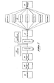
- a first station 100 is provided with a substrate supply in sheet form in a first application. From the substrate supply station 100, the sheets are sequentially fed through first and second metallic ink printers 102, 1'04 to print pluralities of rows of thermocouples, in series, in accordance with the present invention, across the width of each sheet.
- the respective inks are formed by suitable mixtures of finely powdered different metals and a carrier or flux.
- the sheets are passed through a melter 106 where the metallic particles of the thermocouple designs are melted into a solid mass causing an intermingling of the metals at all of couple connections 20, 22.
- the sheets are passed through a slitter station 108 where they are slit into a plurality of thermocouple strips such as 10 and 50 and rotated transversely through 90 degrees into a face to face relationship for passage into a bundler station 110 where the strips of each sheet are packed into a bundle.
- the bundles are sequentially fed to one of a plurality of assembly stations 112 where the bundles are assembled into panels suchas 80,82 ( Figure 5) and from the assembly stations 1,12, the finished panels are fed to an assembled panel collection station 114.
- An adhesive application station 116 is preferably interposed between the melter and slitter stations 106, 108 to secure the strips such as 10 and 50 in a bundle form.
- a sheeter station 118 is provided after the melter station 106.
Landscapes
- Engineering & Computer Science (AREA)
- Manufacturing & Machinery (AREA)
- Measuring Temperature Or Quantity Of Heat (AREA)
- Diaphragms For Electromechanical Transducers (AREA)
- Developing Agents For Electrophotography (AREA)
Applications Claiming Priority (2)
| Application Number | Priority Date | Filing Date | Title |
|---|---|---|---|
| US06/117,342 US4276441A (en) | 1980-02-15 | 1980-02-15 | Thermoelectric generator and method of forming same |
| US117342 | 1980-02-15 |
Publications (2)
| Publication Number | Publication Date |
|---|---|
| EP0034538A2 true EP0034538A2 (fr) | 1981-08-26 |
| EP0034538A3 EP0034538A3 (fr) | 1983-07-27 |
Family
ID=22372370
Family Applications (1)
| Application Number | Title | Priority Date | Filing Date |
|---|---|---|---|
| EP81400231A Withdrawn EP0034538A3 (fr) | 1980-02-15 | 1981-02-13 | Dispositif générateur thermoélectrique et procédé pour le fabriquer |
Country Status (18)
| Country | Link |
|---|---|
| US (1) | US4276441A (fr) |
| EP (1) | EP0034538A3 (fr) |
| JP (1) | JPS56126988A (fr) |
| KR (1) | KR830005731A (fr) |
| AU (1) | AU6727881A (fr) |
| BR (1) | BR8100894A (fr) |
| DD (1) | DD156454A5 (fr) |
| DK (1) | DK65481A (fr) |
| FI (1) | FI810253A7 (fr) |
| GR (1) | GR73834B (fr) |
| HU (1) | HU184528B (fr) |
| IE (1) | IE810284L (fr) |
| IL (1) | IL62128A (fr) |
| IN (1) | IN154039B (fr) |
| NO (1) | NO810496L (fr) |
| OA (1) | OA07374A (fr) |
| PT (1) | PT72473B (fr) |
| ZA (1) | ZA81958B (fr) |
Cited By (12)
| Publication number | Priority date | Publication date | Assignee | Title |
|---|---|---|---|---|
| EP0296738A3 (en) * | 1987-06-23 | 1990-06-13 | British Gas Plc | Miniature thermoelectric converters |
| DE3916311A1 (de) * | 1989-04-24 | 1990-10-25 | Mettler Toledo Ag | Mehrfach-thermoelementfuehler |
| EP0349618A4 (en) * | 1987-10-15 | 1992-03-11 | Virginia Tech Intellectual Properties, Inc. | Heat flux gauge |
| FR2706679A1 (fr) * | 1993-06-15 | 1994-12-23 | Serras Paulet Edouard | Machine de fabrication d'un convertisseur thermoélectrique, et convertisseur ainsi fabriqué. |
| RU2130216C1 (ru) * | 1996-11-26 | 1999-05-10 | Никольский Юрий Анатольевич | Микротермоэлектрогенератор |
| RU2186439C2 (ru) * | 2000-08-24 | 2002-07-27 | Никольский Юрий Анатольевич | Термоэлектрогенератор |
| US6958443B2 (en) | 2003-05-19 | 2005-10-25 | Applied Digital Solutions | Low power thermoelectric generator |
| US7629531B2 (en) | 2003-05-19 | 2009-12-08 | Digital Angel Corporation | Low power thermoelectric generator |
| US7834263B2 (en) | 2003-12-02 | 2010-11-16 | Battelle Memorial Institute | Thermoelectric power source utilizing ambient energy harvesting for remote sensing and transmitting |
| US8455751B2 (en) | 2003-12-02 | 2013-06-04 | Battelle Memorial Institute | Thermoelectric devices and applications for the same |
| US9281461B2 (en) | 2003-12-02 | 2016-03-08 | Battelle Memorial Institute | Thermoelectric devices and applications for the same |
| US20180274986A1 (en) * | 2015-01-28 | 2018-09-27 | Ima Life North America Inc. | Process control using non-invasive printed product sensors |
Families Citing this family (25)
| Publication number | Priority date | Publication date | Assignee | Title |
|---|---|---|---|---|
| US2705546A (en) * | 1949-06-03 | 1955-04-05 | Vokes Ltd | Silencers and air intake filter silencers |
| JPS5672321A (en) * | 1979-11-20 | 1981-06-16 | Kensetsusho Kenchiku Kenkyu Shocho | Radiation thermocouple and its manufacture |
| FR2471055A1 (fr) * | 1979-12-03 | 1981-06-12 | Anvar | Dispositif sensible a un gradient de temperature et son application pour constituer un fluxmetre calorifique ou un capteur solaire |
| US4438291A (en) | 1982-03-08 | 1984-03-20 | General Electric Company | Screen-printable thermocouples |
| US4459428A (en) * | 1982-04-28 | 1984-07-10 | Energy Conversion Devices, Inc. | Thermoelectric device and method of making same |
| US4522511A (en) * | 1982-09-13 | 1985-06-11 | Scientech, Inc. | Method and apparatus for measuring radiant energy |
| JPS59123277A (ja) * | 1982-12-28 | 1984-07-17 | Toki Nagai | 太陽エネルギ−等を利用した複合起電装置 |
| US4465895A (en) * | 1983-06-01 | 1984-08-14 | Ecd-Anr Energy Conversion Company | Thermoelectric devices having improved elements and element interconnects and method of making same |
| US4795498A (en) * | 1983-12-30 | 1989-01-03 | Damon Germanton | Low cost thermocouple apparatus and methods for fabricating the same |
| US4631350A (en) * | 1983-12-30 | 1986-12-23 | Damon Germanton | Low cost thermocouple apparatus and methods for fabricating the same |
| US4640977A (en) * | 1984-04-23 | 1987-02-03 | Omnimax Energy Corporation | Thermoelectric generator using variable geometry with support pedestals of dissimilar materials than the basic thermoelectric semi-conductor elements |
| US4859250A (en) * | 1985-10-04 | 1989-08-22 | Buist Richard J | Thermoelectric pillow and blanket |
| EP0369670A3 (fr) * | 1988-11-18 | 1992-06-03 | Aspden, Harold Dr. | Conversion d'énergie thermo-électrique |
| GB9212585D0 (en) * | 1992-06-13 | 1992-07-29 | Boardman Jeffrey | A method of producing devices which generate electrical energy |
| US5393351A (en) * | 1993-01-13 | 1995-02-28 | The United States Of America As Represented By The Secretary Of Commerce | Multilayer film multijunction thermal converters |
| US5287081A (en) * | 1993-01-13 | 1994-02-15 | The United States Of America As Represented By The Secretary Of Commerce | Multilayer thin film multijunction integrated micropotentiometers |
| US6121539A (en) | 1998-08-27 | 2000-09-19 | International Business Machines Corporation | Thermoelectric devices and methods for making the same |
| US20050257822A1 (en) * | 2004-05-19 | 2005-11-24 | Bed-Check Corporation | Silk-screen thermocouple |
| US20100245090A1 (en) * | 2004-05-19 | 2010-09-30 | Bed-Check Corporation | Patient thermal monitoring system |
| EP1818992A1 (fr) * | 2006-02-08 | 2007-08-15 | Nederlandse Organisatie voor toegepast- natuurwetenschappelijk onderzoek TNO | Élément thermoélectrique thermiquement isolant de toiture |
| WO2009035507A1 (fr) * | 2007-08-30 | 2009-03-19 | Anjun Jerry Jin | Générateur électrique, thermique et solaire à empilement de plusieurs noyaux |
| US9786829B2 (en) | 2010-03-19 | 2017-10-10 | Micropen Technologies Corporation | Thermocouple device |
| US20120192920A1 (en) * | 2011-01-27 | 2012-08-02 | Total Energy Renewable Power Systems, Llc | Stacked Layer High Efficiency Solar Energy Collector |
| KR20140044523A (ko) * | 2012-10-05 | 2014-04-15 | 한국전자통신연구원 | 자가발전장치 |
| US9929332B2 (en) | 2014-04-25 | 2018-03-27 | North Carolina State University | Flexible thermoelectric devices, methods of preparation thereof, and methods of recovering waste heat therewith |
Family Cites Families (7)
| Publication number | Priority date | Publication date | Assignee | Title |
|---|---|---|---|---|
| DE1071177B (fr) * | 1958-01-17 | |||
| US3284245A (en) * | 1961-04-10 | 1966-11-08 | Lockheed Aircraft Corp | Thermoelectric generators |
| CH540580A (de) * | 1970-11-23 | 1973-08-15 | Siemens Ag | Verfahren zur Herstellung eines Thermogenerators |
| SU455702A1 (ru) * | 1973-12-06 | 1976-08-05 | Предприятие П/Я В-2763 | Термоэлемент |
| US4098617A (en) * | 1975-09-23 | 1978-07-04 | Lidorenko Nikolai S | Method of manufacturing film thermopile |
| US4054478A (en) * | 1976-05-25 | 1977-10-18 | Nu-Pak Corporation | Method of manufacturing a thermoelectric device |
| US4111717A (en) * | 1977-06-29 | 1978-09-05 | Leeds & Northrup Company | Small-size high-performance radiation thermopile |
-
1980
- 1980-02-15 US US06/117,342 patent/US4276441A/en not_active Expired - Lifetime
-
1981
- 1981-01-29 FI FI810253A patent/FI810253A7/fi not_active Application Discontinuation
- 1981-02-05 JP JP1627281A patent/JPS56126988A/ja active Pending
- 1981-02-09 PT PT72473A patent/PT72473B/pt unknown
- 1981-02-13 IN IN168/CAL/81A patent/IN154039B/en unknown
- 1981-02-13 AU AU67278/81A patent/AU6727881A/en not_active Abandoned
- 1981-02-13 IL IL62128A patent/IL62128A/xx unknown
- 1981-02-13 DK DK65481A patent/DK65481A/da not_active Application Discontinuation
- 1981-02-13 BR BR8100894A patent/BR8100894A/pt unknown
- 1981-02-13 NO NO810496A patent/NO810496L/no unknown
- 1981-02-13 IE IE810284A patent/IE810284L/xx unknown
- 1981-02-13 OA OA57325A patent/OA07374A/fr unknown
- 1981-02-13 HU HU81353A patent/HU184528B/hu unknown
- 1981-02-13 ZA ZA00810958A patent/ZA81958B/xx unknown
- 1981-02-13 EP EP81400231A patent/EP0034538A3/fr not_active Withdrawn
- 1981-02-14 KR KR1019810000465A patent/KR830005731A/ko not_active Ceased
- 1981-02-16 DD DD81227657A patent/DD156454A5/de unknown
- 1981-02-16 GR GR64152A patent/GR73834B/el unknown
Cited By (18)
| Publication number | Priority date | Publication date | Assignee | Title |
|---|---|---|---|---|
| EP0296738A3 (en) * | 1987-06-23 | 1990-06-13 | British Gas Plc | Miniature thermoelectric converters |
| US4971632A (en) * | 1987-06-23 | 1990-11-20 | British Gas Plc | Miniature thermoelectric converters |
| US4983225A (en) * | 1987-06-23 | 1991-01-08 | British Gas Plc | Process of manufacturing miniature thermoelectric converters |
| EP0349618A4 (en) * | 1987-10-15 | 1992-03-11 | Virginia Tech Intellectual Properties, Inc. | Heat flux gauge |
| DE3916311C2 (de) * | 1989-04-24 | 2002-02-07 | Mettler Toledo Gmbh | Mehrfach-Thermoelementfühler |
| US5033866A (en) * | 1989-04-24 | 1991-07-23 | Mettler Toledo Ag | Multiple thermocouple sensor |
| DE3916311A1 (de) * | 1989-04-24 | 1990-10-25 | Mettler Toledo Ag | Mehrfach-thermoelementfuehler |
| FR2706679A1 (fr) * | 1993-06-15 | 1994-12-23 | Serras Paulet Edouard | Machine de fabrication d'un convertisseur thermoélectrique, et convertisseur ainsi fabriqué. |
| RU2130216C1 (ru) * | 1996-11-26 | 1999-05-10 | Никольский Юрий Анатольевич | Микротермоэлектрогенератор |
| RU2186439C2 (ru) * | 2000-08-24 | 2002-07-27 | Никольский Юрий Анатольевич | Термоэлектрогенератор |
| US7629531B2 (en) | 2003-05-19 | 2009-12-08 | Digital Angel Corporation | Low power thermoelectric generator |
| US6958443B2 (en) | 2003-05-19 | 2005-10-25 | Applied Digital Solutions | Low power thermoelectric generator |
| US8269096B2 (en) | 2003-05-19 | 2012-09-18 | Ingo Stark | Low power thermoelectric generator |
| US7834263B2 (en) | 2003-12-02 | 2010-11-16 | Battelle Memorial Institute | Thermoelectric power source utilizing ambient energy harvesting for remote sensing and transmitting |
| US8455751B2 (en) | 2003-12-02 | 2013-06-04 | Battelle Memorial Institute | Thermoelectric devices and applications for the same |
| US9281461B2 (en) | 2003-12-02 | 2016-03-08 | Battelle Memorial Institute | Thermoelectric devices and applications for the same |
| US20180274986A1 (en) * | 2015-01-28 | 2018-09-27 | Ima Life North America Inc. | Process control using non-invasive printed product sensors |
| US10641661B2 (en) * | 2015-01-28 | 2020-05-05 | Ima Life North America Inc. | Process control using non-invasive printed product sensors |
Also Published As
| Publication number | Publication date |
|---|---|
| ZA81958B (en) | 1982-03-31 |
| DK65481A (da) | 1981-08-16 |
| IL62128A (en) | 1984-07-31 |
| US4276441A (en) | 1981-06-30 |
| IN154039B (fr) | 1984-09-15 |
| DD156454A5 (de) | 1982-08-25 |
| GR73834B (fr) | 1984-05-04 |
| OA07374A (fr) | 1984-06-30 |
| PT72473B (en) | 1982-02-26 |
| NO810496L (no) | 1981-08-17 |
| AU6727881A (en) | 1981-08-20 |
| EP0034538A3 (fr) | 1983-07-27 |
| FI810253L (fi) | 1981-08-16 |
| KR830005731A (ko) | 1983-09-09 |
| HU184528B (en) | 1984-09-28 |
| IE810284L (en) | 1981-08-15 |
| IL62128A0 (en) | 1981-03-31 |
| FI810253A7 (fi) | 1981-08-16 |
| PT72473A (en) | 1981-03-01 |
| JPS56126988A (en) | 1981-10-05 |
| BR8100894A (pt) | 1981-08-25 |
Similar Documents
| Publication | Publication Date | Title |
|---|---|---|
| US4276441A (en) | Thermoelectric generator and method of forming same | |
| US2519785A (en) | Thermopile | |
| US5006178A (en) | Thermo-electric device with each element containing two halves and an intermediate connector piece of differing conductivity | |
| DE4329816A1 (de) | Thermoelementplatte oder Flächenelement | |
| GB1050798A (fr) | ||
| JP2003533031A5 (fr) | ||
| CN1969400B (zh) | 热电装置 | |
| US20090277489A1 (en) | Thermoelectric Device | |
| JPS5657289A (en) | Heater with positive temperature coefficient thermistor heater | |
| US4049469A (en) | Film thermoelement | |
| US3432923A (en) | Method of manufacturing fuse elements from strip material for cartridge fuse links | |
| US20050028858A1 (en) | Thermoelectric module and generator | |
| GB1445509A (en) | Welding jaw | |
| CA1167091A (fr) | Generateur thermoelectrique et methode de fabrication | |
| US3183121A (en) | Thermoelectric generator with heat transfer and thermal expansion adaptor | |
| Henderson | Analysis of a heat exchanger-thermoelectric generator system | |
| US3284245A (en) | Thermoelectric generators | |
| US2951105A (en) | Thermoelectric compositions and elements and devices using them | |
| CN210381343U (zh) | 电加热膜及安装其的电加热器 | |
| US20190165236A1 (en) | Thermo-electric device to provide electrical power | |
| CN113228823B (zh) | 具有熔断功能的发热元件及包括此的加热单元 | |
| US3145071A (en) | High speed thermal contact printer | |
| KR101544083B1 (ko) | 휴대용 열전 충전장치 및 그 제조방법 | |
| US4363927A (en) | Thermoelectric generator panel and heater device therefor | |
| CN106992244B (zh) | 热电转换装置以及热电转换器 |
Legal Events
| Date | Code | Title | Description |
|---|---|---|---|
| PUAI | Public reference made under article 153(3) epc to a published international application that has entered the european phase |
Free format text: ORIGINAL CODE: 0009012 |
|
| AK | Designated contracting states |
Designated state(s): AT BE CH DE FR GB IT LU NL SE |
|
| PUAL | Search report despatched |
Free format text: ORIGINAL CODE: 0009013 |
|
| AK | Designated contracting states |
Designated state(s): AT BE CH DE FR GB IT LI LU NL SE |
|
| 17P | Request for examination filed |
Effective date: 19840123 |
|
| STAA | Information on the status of an ep patent application or granted ep patent |
Free format text: STATUS: THE APPLICATION IS DEEMED TO BE WITHDRAWN |
|
| 18D | Application deemed to be withdrawn |
Effective date: 19840831 |