EP0034873A2 - Appareil de contrôle du gouvernail d'un avion - Google Patents
Appareil de contrôle du gouvernail d'un avion Download PDFInfo
- Publication number
- EP0034873A2 EP0034873A2 EP81200220A EP81200220A EP0034873A2 EP 0034873 A2 EP0034873 A2 EP 0034873A2 EP 81200220 A EP81200220 A EP 81200220A EP 81200220 A EP81200220 A EP 81200220A EP 0034873 A2 EP0034873 A2 EP 0034873A2
- Authority
- EP
- European Patent Office
- Prior art keywords
- output
- summer
- signals
- producing
- input
- Prior art date
- Legal status (The legal status is an assumption and is not a legal conclusion. Google has not performed a legal analysis and makes no representation as to the accuracy of the status listed.)
- Granted
Links
Images


Classifications
-
- G—PHYSICS
- G05—CONTROLLING; REGULATING
- G05D—SYSTEMS FOR CONTROLLING OR REGULATING NON-ELECTRIC VARIABLES
- G05D1/00—Control of position, course, altitude or attitude of land, water, air or space vehicles, e.g. using automatic pilots
- G05D1/0055—Control of position, course, altitude or attitude of land, water, air or space vehicles, e.g. using automatic pilots with safety arrangements
- G05D1/0077—Control of position, course, altitude or attitude of land, water, air or space vehicles, e.g. using automatic pilots with safety arrangements using redundant signals or controls
-
- G—PHYSICS
- G05—CONTROLLING; REGULATING
- G05B—CONTROL OR REGULATING SYSTEMS IN GENERAL; FUNCTIONAL ELEMENTS OF SUCH SYSTEMS; MONITORING OR TESTING ARRANGEMENTS FOR SUCH SYSTEMS OR ELEMENTS
- G05B9/00—Safety arrangements
- G05B9/02—Safety arrangements electric
- G05B9/03—Safety arrangements electric with multiple-channel loop, i.e. redundant control systems
Definitions
- the present invention pertains to the electronic control art and, more particularly, to improved fault detection and equalizing apparatus for the same.
- a controller responds to two or more parameter sense signals to produce a controlled output.
- Specific applications for electronic controllers to which the preferred embodiments of the invention are addressed are aircraft electrohydraulic feel force generating systems and rudder ratio changer servo loops. Both of these systems relate to the safe operation of an aircraft and, as such, should be precise in operation.
- a controller should include fault detection circuitry which accurately and quickly indicates the condition of a fault in the system.
- the controller should include equalization circuitry to eliminate fault indications which would otherwise be caused by system tolerances.
- an electronic controller produces a controlled output in response to a pair of input signals.
- the controller includes a means which processes the input signals, passing the processed signals to the inputs of a pair of summers.
- The. output from the summers couple to inputs of a pair of servo amplifiers.
- the servo amplifier outputs are utilized by an appropriate utilization means.
- Feedback circuitry senses the status of the utilization means and produces negative feedback signals which are coupled as inputs to the summer means such that for ideal operation of the electronic controller the output signals from the servo amplifiers are identical.
- a comparator compares the two servo amplifier output signals and produces a difference signal related to the difference therebetween.
- Threshold warning circuitry produces a warning indication in response to the difference signal at the comparator output exceeding a predetermined reference level, thereby detecting a fault condition.
- equalizer circuitry processes the difference signal at the comparator output and applies a negative feedback correction signal to an input of each summer thereby reducing offsets between the servo amplifier outputs due to system tolerances.
- FIG. 1 illustrates the preferred embodiment of an aircraft electrohydraulic feel force generating system according to the invention.
- the purpose of such systems is to apply a force to the pilot's column representative of aircraft airspeed and stabilizer position. This gives the pilot a "feel" of the status of the aircraft and results in the pilot always having to apply a constant force on his column to achieve a given change in the aircraft.
- sensors 10-13 monitor aircraft parameters.
- Sensors 10 and 12 are redundant impact pressure airspeed indicating signals, as are commonly supplied by pitot static sensors. These produce signals q,, q 2 corresponding to aircraft airspeed.
- Sensors 11 and 13 are redundant stabilizer position sensors producing signals s 1 and s 2 corresponding to the aircraft's stabilizer position.
- the signals q l and s 1 are fed to inputs of a first electronic controller 14.
- the signals q 2 and s 2 are fed to inputs of a second electronic controller 16. While the preferred construction of the electronic controllers 14, 16 is shown in detail in FIG. 2, for purposes of FIG. 1 it should be understood that each electronic controller 14, 16 includes processing circuitry for producing output control signals corresponding to a desired feel pressure for the given input signals.
- the output control signals from electronic controller 14 are routed to a pressure module 18 whereas the output signals from electronic controller 16 are passed to a pressure module 20.
- the pressure modules 18, 20 produce hydraulic pressures corresponding to the signals from the electronic controllers 14, 16. These pressures are applied to driving a feel actuator, as will be described hereinafter.
- a differential pressure monitor 22 monitors the pressure difference between pressure module 18 and pressure module 20 and produces a warning indication if the difference between the pressure levels exceeds a reference level.
- the output from the pressure modules 18, 20 are routed to a standard feel and centering mechanism, indicated generally at 24.
- a feel actuator 26 At the input of feel and centering mechanism 24, and receiving the hydraulic pressure from pressure modules 18, 20 is a feel actuator 26.
- Feel actuator 26 is comprised of a cylinder section 28 and a pair of pistons 30, 32.
- the rod from piston 30 pivotally connects to a base plate 34 whereas the rod from piston 32 pivotally connects to a pivot lever 36 which, in turn, connects to a tie bar 38.
- Tie bar 38 connects to tie straps 40, 42 which, via suitably provided slots, connect to pins provided on a centering cam plate 44.
- centering cam plate 44 Extending from centering cam plate 44 is the output crank 46 which connects through a linkage- (not shown) to the elevator control system, thereby providing a resistive force to the pilot's column.
- a roller 50 provided on a lever arm 52 rides in a V-slot provided in centering cam plate 44.
- One end of lever 52 is spring loaded to the base plate 34 via centering springs 54.
- operation of the feel and centering mechanism 24 in accordance with input pressures from pressure modules 18 and 20 may be understood as follows. If, for example, the pressure from pressure module 18 exceeds that provided from pressure module 20, the cylinder 28 moves in the direction indicated by arrow 56 until the piston 32 bottoms on the cylinder surface.' This results in the force acting on lever 36 being determined by the pressure from module 18.
- centering spring 54 and roller 50 assure a minimum feel force backup to the system.
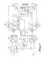
- FIG. 2 is a detailed schematic diagram showing the preferred construction of each of the electronic controllers 14, 16.
- the stabilizer position signal s is passed to a feel pressure limit block 60.
- block 60 determines a corresponding feel pressure limit, in pounds per square inch, in accordance with a predetermined function, here indicated as 62.
- the function 62 is determined for a given aircraft configuration.
- the feel pressure limit signal from block 60 is routed to feel pressure command blocks 64, 66. Also passed to the feel pressure command blocks 64, 66 is the signal q, representative of aircraft airspeed. Blocks 64, 66 contain identical transfer functions, here indicated graphically, which produce an output feel pressure command signal corresponding to the signal q, and the signal s as processed through. feel pressure limit block 60. As with the transfer function of block 60, the exact functional relationship between the input signals to block 64 and its feel pressure command output signal is related to a given aircraft configuration.
- the feel pressure command signal from each of the feel pressure command blocks 64, 66 is passed to an input of a pair of summers 70, 72, respectively.
- Each summer 70, 72 in the conventional manner, produces an output signal equal to the sum and/or difference of signals applied to its inputs.
- each summer 70, 72 is passed to the input of servo amplifiers 74, 76, respectively.
- Amplifiers 74, 76 may include low pass circuitry to eliminate high frequency noise.
- each servo amplifier 74, 76 is designed to saturate at a predetermined current level .for reasons which will be discussed herein below.
- each servo amplifier 74, 76 was designed to saturate at ⁇ 8 milliamperes.
- the output signals from the servo amplifiers 74, 76 are passed to a T-valve/manifold unit 80, which comprises each of the pressure modules 18, 20 of FIG. 1.
- the T-valve which is a readily available electrohydraulic component, sums the currents from the servo amplifers 74, 76 and provides a predetermined hydraulic flow as a function thereof. This flow, as routed to the manifold portion of block 80, results in a corresponding feel pressure output.
- a mechanical bias, here indicated as provided from block 82 is coupled to the T-valve in unit 80.
- each servo amplifier 74, 76 is designed to saturate at ⁇ 8 milliamp current
- the mechanical bias 82 requires a total of 8 milliamps of input current for the T-valve to be at null (no change in pressure).
- one channel fails high (i.e. one channel produces 8 milliamps continuously regardless of its - input) the system will servo back via its feedback as is discussed herein below resulting in a negative current supplied from the remaining operable servo amplifier thereby tending to correct for the fault.
- the pressure produced from the T-valve/manifold unit 80 is monitored by a pair of pressure transducers 90, 92, each comprised of a bellow with a suitable spring rate and a linear variable differential transformer.
- the transformers 90, 92 operating in the well known manner, produce an AC signal corresponding to the pressure at the output of unit 80.
- These AC signals are suitably demodulated in a pair of demodulators 94, 96, thereby producing DC signals representative of output feel pressure.
- the outputs from demodulators 94, 96 are passed to summers 70, 72 respectively in a negative sense, thereby forming negative feedback loops around servo amplifiers 74, 76 respectively.
- a warning indication as by a warning light, is produced on an output line 106.
- This warning indication would normally be supplied to the flight deck thereby indicating to the pilot that a fault has occurred in the feel force generating system.
- Equalizing circuit 110 which acts as a slow integrator, produces an output equalizing signal which is fed in a negative sense to summer circuit 70 and in a positive sense to summer circuit 72.
- equalizer 110 permits a high loop gain to be used in servo amplifiers 74, 76, thus assuring a high degree of system precision, but prevents system component tolerances from tripping the warning system, comprised of threshold detector 102 and time delay 104. Since the equalizing signal is fed back into each servo loop in an opposite sense, the resulting feel pressure is the average of the two commands.
- the equalizing signal is limited, in limiter lll, so as to prevent a slow failure of one servo loop to a high or low pressure command from being undetected by the monitor.
- the electronic controller as shown in FIG. 2 provides a precise and fast method for determining that a fault has occurred in the system and further provides an equalizer which compensates for system tolerances to eliminate nuisance fault detections which would otherwise occur.
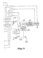
- FIG. 3 is a detailed schematic diagram illustrating the preferred embodiment of an aircraft rudder ratio changer system.
- This system is comprised of two identical electronic channels 120, 122 and one electrohydraulic servo 124.
- Inputs to the system include four aircraft airspeed sense signals ql-g4, as may be supplied by conventional airspeed sensors or may be computed airspeed values.
- the airspeed signals ql, q 2 are applied to the first electronic channel 120, whereas the signals q 3 and q 4 are applied to the second electronic channel 122.
- this preferred embodiment of the invention employs a quadruple redundant airspeed sense system.
- the electronic channel 120 is the primary channel whereas channel 122 is a standby channel.
- the topology of the second electronic channel 122 is very similar to the first 120 and, as such, only the differences therebetween will be discussed.
- the input airspeed sense signals q ,, q 2 are applied to input program blocks 130, 132, respectively.
- the program blocks 130, 132 produce an output actuator position signal which is a predetermined function of the input airspeed sense signal. This functional relationship, as will be understood by anyone of ordinary skill in this art, is designer selected based upon the desired operation of the system.
- the actuator position command signals from the outputs of program blocks 130, 132 are passed to inputs of respective summers 134, 136.
- the outputs from the summers are coupled to corresponding servo amplifiers 140, 142.
- the outputs from servo amplifiers 140, 142 are passed through a relay, indicated generally at 150 which, as shown, is in a position to select the outputs from electronic channel 120.
- the outputs of servo amplifiers 140, 142 are applied as inputs to a T-valve 152.
- T-valve 152 acting in the conventional manner, controls hydraulic flow at its output in response to the sum of the electrical signals applied at its inputs.
- the output from T-valve 152 controls the rudder ratio changer actuator 154.
- Two linear variable differential transducers 156 sense the position of the actuator and, in response thereto, produces AC feedback signals which are routed through the relay 150 to demodulators 160, 162.
- the demodulators 160, 162 produce output DC control signals corresponding to the AC input signals. These DC control signals are applied to the summers 134, 136 in a negative sense, thus realizing negative feedback loops around amplifiers 140, 142, respectively.
- the feedback loops around the servo amplifiers 140, 142 tend to cause the outputs thereof to be approximately equal for normal system operation.
- a failure associated with one of the servo amplifiers 140, 142 this is sensed by a comparator 170 which constantly monitors the difference between the outputs of amplifiers 140, 142. Should the difference exceed a reference level, as determined by monitor 172, a fault condition is detected and the monitor causes an alternate channel indicating lamp "ALT" 174 to light in the cockpit indicating the detected failure. Also, monitor 172 produces a current through the coil 150a of relay 150 thereby activating all of the contacts of relay 150 to their alternate state thereby switching control from electronic channel 120 to electronic channel 122. Electronic channel 122 will continue to run the system in response to its input signals q 3 and q 4 in a manner identical to that of electronic channel 120.
- Equalizer 190 is a slow integrator which senses the servo amplifier difference signal as produced by comparator 170 and provides an equalization signal at its output which is passed in a positive sense to summer 136 and in a negative sense to summer 134.
- the net effect on T-valve 152 is an average of the two equalizer commands, and the two servo amplifiers 140, 142 will, for normal operation, have equal outputs. Equalizing the two servo amplifiers prevents normal system tolerances from tripping the monitor.
- the equalizing signal is passed through a limiter, 191, to prevent a slow failure of one servo loop to a low or high position command from being undetected by the monitor 120.
- the system also includes a safety mode should either the T-valve 152 or actuator 154 fail.
- the servo amplifiers in the electronic channel 120 or 122 whichever is controlling the system, would both saturate to their limits in the same direction.
- an amplifier 200 sums the two servo amplifier output signals and passes these to a monitor 202. Should the monitor detect that the sum of the two servo amplifier outputs exceed a reference threshold, it produces an output indication which is applied as one input to an OR gate 204.
- the output of AND gate 206 which is passed to OR gate 204, indicates a failure of channel 122 when this channel is in control.
- the final input to OR gate 204 is from the output of AND gate 220.
- the inputs to AND gate 220 are the output from monitor 202 and the output from the identical monitor 222 of the second electronic channel 122. Thus, if both monitors 202 and 222 indicate that their respective channels have failed AND gate 220 is satisfied and produces an output to OR gate 204.
- OR gate 204 If any of the inputs to OR gate 204 is activated, indicative of a total system failure, OR gate 204 both lights a failure light 224 in the cockpit, thereby notifying the flight crew of the failure and produces a signal which is coupled to delay block 230.
- Delay block 230 only produces an output if its input level is activated for a sufficient period of time. This thereby eliminates transient type system failure indications.
- delay block 230 receives an input signal for a sufficient period of time, it produces an output signal which is coupled through the coil 240 of a relay 242. With the relay activated, bias is removed from a solenoid valve 244 which shuts off hydraulic pressure to the T-valve 124.
- a bias spring (not shown) drives the actuator to the full rudder authority position.
- the disclosed rudder ratio changer system provides a fast and accurate means for switching from a faulty main channel to a standby channel and, in the event of total system failure, for indicating such failure and deactivating the system from ratio changer control.
Landscapes
- Engineering & Computer Science (AREA)
- Physics & Mathematics (AREA)
- General Physics & Mathematics (AREA)
- Automation & Control Theory (AREA)
- Aviation & Aerospace Engineering (AREA)
- Radar, Positioning & Navigation (AREA)
- Remote Sensing (AREA)
- Safety Devices In Control Systems (AREA)
- Fluid-Pressure Circuits (AREA)
- Testing And Monitoring For Control Systems (AREA)
Applications Claiming Priority (2)
| Application Number | Priority Date | Filing Date | Title |
|---|---|---|---|
| US06/124,366 US4398242A (en) | 1980-02-25 | 1980-02-25 | Electronic controller |
| US124366 | 1980-02-25 |
Publications (4)
| Publication Number | Publication Date |
|---|---|
| EP0034873A2 true EP0034873A2 (fr) | 1981-09-02 |
| EP0034873A3 EP0034873A3 (en) | 1982-03-31 |
| EP0034873B1 EP0034873B1 (fr) | 1985-07-24 |
| EP0034873B2 EP0034873B2 (fr) | 1989-12-27 |
Family
ID=22414435
Family Applications (1)
| Application Number | Title | Priority Date | Filing Date |
|---|---|---|---|
| EP81200220A Expired EP0034873B2 (fr) | 1980-02-25 | 1981-02-23 | Appareil de contrôle du gouvernail d'un avion |
Country Status (4)
| Country | Link |
|---|---|
| US (1) | US4398242A (fr) |
| EP (1) | EP0034873B2 (fr) |
| JP (1) | JPS56155411A (fr) |
| DE (1) | DE3171443D1 (fr) |
Cited By (3)
| Publication number | Priority date | Publication date | Assignee | Title |
|---|---|---|---|---|
| EP0093276A3 (en) * | 1982-04-15 | 1984-09-05 | General Electric Company | Turbine control system |
| EP2826707A1 (fr) * | 2013-07-16 | 2015-01-21 | McCulloch, Norman L | Système de rétroaction pour un élément de commande de vol |
| GB2516248A (en) * | 2012-11-16 | 2015-01-21 | Norman L Mcculloch | Improvements in aircraft |
Families Citing this family (10)
| Publication number | Priority date | Publication date | Assignee | Title |
|---|---|---|---|---|
| IT1169167B (it) * | 1983-02-15 | 1987-05-27 | Gd Spa | Sistema di controllo funzionale per trasduttori di uscita di un'unita' centrale di controllo e comando per macchine e/o dispositivi utilizzabili in linee di produzione e/o confezionamento di prodotti |
| JPH01185709A (ja) * | 1988-01-20 | 1989-07-25 | Teijin Seiki Co Ltd | 故障検出機構付きサーボ回路 |
| US5555269A (en) * | 1993-10-29 | 1996-09-10 | Carrier Corporation | Error detection for HVAC systems |
| US5806805A (en) * | 1996-08-07 | 1998-09-15 | The Boeing Company | Fault tolerant actuation system for flight control actuators |
| US6003811A (en) * | 1997-03-24 | 1999-12-21 | The Boeing Company | Aircraft servovalve current rate limiter |
| JPH11161312A (ja) * | 1997-11-26 | 1999-06-18 | Fanuc Ltd | 数値制御装置 |
| US20110017868A1 (en) * | 2005-11-18 | 2011-01-27 | Honeywell International Inc. | Aircraft cabin pressure control system and method for aircraft having multiple differential pressure limits |
| US7752914B2 (en) * | 2007-11-15 | 2010-07-13 | Venturedyne, Ltd. | Monitoring of independent vibrators |
| CN106325218B (zh) * | 2016-08-18 | 2019-03-01 | 深圳市优必选科技有限公司 | 一种伺服器、伺服器控制系统及其通信方法 |
| CN114089707B (zh) * | 2021-11-18 | 2023-09-22 | 佛山冠湾智能科技有限公司 | 一种伺服驱动系统报警装置及报警方法 |
Family Cites Families (27)
| Publication number | Priority date | Publication date | Assignee | Title |
|---|---|---|---|---|
| US2544286A (en) * | 1945-01-15 | 1951-03-06 | Tanner Joseph Alan | Electric motor control system |
| US2953325A (en) * | 1955-07-29 | 1960-09-20 | Sperry Gyroscope Co Ltd | Control systems for aircraft |
| US3054039A (en) * | 1957-09-05 | 1962-09-11 | Meredith Dennis Lello | Plural channel servo systems |
| US3070071A (en) * | 1960-03-11 | 1962-12-25 | North American Aviation Inc | Failure protected signal translating system |
| US3120787A (en) * | 1963-01-11 | 1964-02-11 | Vernon R Schmitt | Dual flight control system |
| GB1098194A (en) * | 1964-07-07 | 1968-01-10 | Hobson Ltd H M | Improvements in position control servo systems |
| US3279323A (en) * | 1964-09-28 | 1966-10-18 | North American Aviation Inc | Electrohydraulic actuator |
| US3377924A (en) * | 1965-03-02 | 1968-04-16 | Gen Electric | Synchronizing control circuit |
| US3422327A (en) * | 1965-09-17 | 1969-01-14 | Sperry Rand Corp | Multiple channel fail functional system for discretely disconnecting malfunctioning sub-systems |
| US3401904A (en) * | 1967-01-03 | 1968-09-17 | Sperry Rand Corp | Cross-channel monitoring for aircraft |
| US3489379A (en) * | 1968-03-20 | 1970-01-13 | Bill B Bogart | Stick force optimizer |
| US3618470A (en) * | 1969-06-25 | 1971-11-09 | Ver Flugtechnische Werke | Device for supervising electro-hydraulic actuators |
| US3626809A (en) * | 1970-09-29 | 1971-12-14 | Gen Electric | Bilateral servosystem |
| GB1334531A (en) * | 1971-04-19 | 1973-10-17 | Atomic Energy Authority Uk | Automatic control systems which employ redundancy |
| US3733039A (en) * | 1971-05-20 | 1973-05-15 | United Aircraft Corp | Feel augmentation control system for helicopters |
| US3700995A (en) * | 1971-05-20 | 1972-10-24 | United Aircraft Corp | Trim reference for helicopter feel augmentation system |
| US3724330A (en) * | 1971-07-12 | 1973-04-03 | Textron Inc | Self monitoring control system utilizing an electrical model for each control means |
| US3827659A (en) * | 1973-03-07 | 1974-08-06 | Bendix Corp | Control system monitoring apparatus having minimal nuisance alarm characteristics |
| JPS50157778A (fr) * | 1974-06-12 | 1975-12-19 | ||
| FR2275833A1 (fr) * | 1974-06-19 | 1976-01-16 | Commissariat Energie Atomique | Dispositif de commande a distance mecanique reversible |
| US4035705A (en) * | 1975-03-17 | 1977-07-12 | Sperry Rand Corporation | Fail-safe dual channel automatic pilot with maneuver limiting |
| FR2347257A1 (fr) * | 1976-04-05 | 1977-11-04 | Aerospatiale | Dispositif de servocommande pour la commande d'une gouverne d'aeronef |
| US4095763A (en) * | 1977-02-25 | 1978-06-20 | Textron, Inc. | Fail safe augmentation system |
| US4094481A (en) * | 1977-06-30 | 1978-06-13 | Sperry Rand Corporation | Fail passive dual servo with continuous motor speed and acceleration and monitoring |
| DE2807902C2 (de) * | 1978-02-24 | 1980-04-30 | Messerschmitt-Boelkow-Blohm Gmbh, 8000 Muenchen | Steuereinrichtung mit aktiver Kraft rückführung |
| US4209734A (en) * | 1978-03-27 | 1980-06-24 | Sperry Corporation | Dynamic equalization system for dual channel automatic pilot |
| US4228386A (en) * | 1978-06-02 | 1980-10-14 | Sperry Corporation | Aircraft servoactuator apparatus |
-
1980
- 1980-02-25 US US06/124,366 patent/US4398242A/en not_active Expired - Lifetime
-
1981
- 1981-02-23 DE DE8181200220T patent/DE3171443D1/de not_active Expired
- 1981-02-23 EP EP81200220A patent/EP0034873B2/fr not_active Expired
- 1981-02-24 JP JP2602981A patent/JPS56155411A/ja active Pending
Cited By (6)
| Publication number | Priority date | Publication date | Assignee | Title |
|---|---|---|---|---|
| EP0093276A3 (en) * | 1982-04-15 | 1984-09-05 | General Electric Company | Turbine control system |
| GB2516248A (en) * | 2012-11-16 | 2015-01-21 | Norman L Mcculloch | Improvements in aircraft |
| GB2521814A (en) * | 2012-11-16 | 2015-07-08 | Norman L Mcculloch | Improvements in aircraft |
| GB2521814B (en) * | 2012-11-16 | 2018-11-14 | L Mcculloch Norman | A feedback system for a flying control member of an aircraft |
| EP2826707A1 (fr) * | 2013-07-16 | 2015-01-21 | McCulloch, Norman L | Système de rétroaction pour un élément de commande de vol |
| EP3594111A1 (fr) | 2013-07-16 | 2020-01-15 | McCulloch, Norman L | Système de rétroaction pour un élément de commande de vol |
Also Published As
| Publication number | Publication date |
|---|---|
| DE3171443D1 (en) | 1985-08-29 |
| JPS56155411A (en) | 1981-12-01 |
| EP0034873B1 (fr) | 1985-07-24 |
| EP0034873A3 (en) | 1982-03-31 |
| US4398242A (en) | 1983-08-09 |
| EP0034873B2 (fr) | 1989-12-27 |
Similar Documents
| Publication | Publication Date | Title |
|---|---|---|
| US4398242A (en) | Electronic controller | |
| EP0288034A2 (fr) | Système de commande de vol utilisant trois organes de commande mettant en action un double actionneur | |
| US4159444A (en) | Fail operational dual electromechanical servo actuator for aircraft with model monitoring | |
| US4887214A (en) | Flight control system employing two dual controllers operating a dual actuator | |
| US4472780A (en) | Fly-by-wire lateral control system | |
| US5515282A (en) | Method and apparatus for implementing a databus voter to select flight command signals from one of several redundant asynchronous digital primary flight computers | |
| CA1114925A (fr) | Systeme d'egalisation dynamique pour pilote automatique a deux voies | |
| EP0321758B1 (fr) | Systèmes actionneurs électro-hydrauliques | |
| US3665809A (en) | Multiple channel redundant control system | |
| EP0573106A1 (fr) | Système de commande de vol primaire multiaxial redondant électrique | |
| US4078750A (en) | Speed-variable limits in fail-safe actuators | |
| GB2084349A (en) | Controller for dual servo system | |
| EP0098719B1 (fr) | Valve hydraulique à commande par double rétroaction | |
| US4594537A (en) | Redundant control system for X-wing valve actuators | |
| US4257311A (en) | Control systems | |
| US3882406A (en) | Fault suppressing signal selection apparatus | |
| US4120469A (en) | In-line actuator monitoring and control apparatus | |
| US4542679A (en) | Multiple loop control system | |
| CA1329645C (fr) | Systeme de surveillance de securite comportant un potentiometre | |
| CA1092712A (fr) | Appareil de surveillance ou de correction de signaux electriques | |
| US4436018A (en) | Multiple loop control system | |
| US3521229A (en) | Safety device for use in aircraft during automatic landing | |
| GB1560554A (en) | Control systems | |
| US4612844A (en) | Fail-passive actuator control | |
| US3219295A (en) | Triple safety control system |
Legal Events
| Date | Code | Title | Description |
|---|---|---|---|
| PUAI | Public reference made under article 153(3) epc to a published international application that has entered the european phase |
Free format text: ORIGINAL CODE: 0009012 |
|
| AK | Designated contracting states |
Designated state(s): DE FR GB IT NL SE |
|
| PUAL | Search report despatched |
Free format text: ORIGINAL CODE: 0009013 |
|
| AK | Designated contracting states |
Designated state(s): DE FR GB IT NL SE |
|
| 17P | Request for examination filed |
Effective date: 19820205 |
|
| ITF | It: translation for a ep patent filed | ||
| GRAA | (expected) grant |
Free format text: ORIGINAL CODE: 0009210 |
|
| AK | Designated contracting states |
Designated state(s): DE FR GB IT NL SE |
|
| PG25 | Lapsed in a contracting state [announced via postgrant information from national office to epo] |
Ref country code: SE Effective date: 19850730 |
|
| REF | Corresponds to: |
Ref document number: 3171443 Country of ref document: DE Date of ref document: 19850829 |
|
| ET | Fr: translation filed | ||
| PLBI | Opposition filed |
Free format text: ORIGINAL CODE: 0009260 |
|
| 26 | Opposition filed |
Opponent name: MESSERSCHMIDT - BOELKOW - BLOHM GMBH, OTTOBRUNN Effective date: 19860416 |
|
| NLR1 | Nl: opposition has been filed with the epo |
Opponent name: MESSERSCHMIDT-BOELKOW-BLOHM GMBH |
|
| ITF | It: translation for a ep patent filed | ||
| PUAH | Patent maintained in amended form |
Free format text: ORIGINAL CODE: 0009272 |
|
| STAA | Information on the status of an ep patent application or granted ep patent |
Free format text: STATUS: PATENT MAINTAINED AS AMENDED |
|
| 27A | Patent maintained in amended form |
Effective date: 19891227 |
|
| AK | Designated contracting states |
Kind code of ref document: B2 Designated state(s): DE FR GB IT NL SE |
|
| ET3 | Fr: translation filed ** decision concerning opposition | ||
| NLR2 | Nl: decision of opposition | ||
| NLR3 | Nl: receipt of modified translations in the netherlands language after an opposition procedure | ||
| PGFP | Annual fee paid to national office [announced via postgrant information from national office to epo] |
Ref country code: GB Payment date: 19920213 Year of fee payment: 12 |
|
| PGFP | Annual fee paid to national office [announced via postgrant information from national office to epo] |
Ref country code: DE Payment date: 19920227 Year of fee payment: 12 |
|
| ITTA | It: last paid annual fee | ||
| PGFP | Annual fee paid to national office [announced via postgrant information from national office to epo] |
Ref country code: NL Payment date: 19920229 Year of fee payment: 12 |
|
| PGFP | Annual fee paid to national office [announced via postgrant information from national office to epo] |
Ref country code: FR Payment date: 19921229 Year of fee payment: 13 |
|
| PG25 | Lapsed in a contracting state [announced via postgrant information from national office to epo] |
Ref country code: GB Effective date: 19930223 |
|
| PG25 | Lapsed in a contracting state [announced via postgrant information from national office to epo] |
Ref country code: NL Effective date: 19930901 |
|
| NLV4 | Nl: lapsed or anulled due to non-payment of the annual fee | ||
| GBPC | Gb: european patent ceased through non-payment of renewal fee |
Effective date: 19930223 |
|
| PG25 | Lapsed in a contracting state [announced via postgrant information from national office to epo] |
Ref country code: FR Effective date: 19931029 |
|
| PG25 | Lapsed in a contracting state [announced via postgrant information from national office to epo] |
Ref country code: DE Effective date: 19931103 |
|
| REG | Reference to a national code |
Ref country code: FR Ref legal event code: ST |