EP0034884A2 - Absperrventilvorrichtung - Google Patents
Absperrventilvorrichtung Download PDFInfo
- Publication number
- EP0034884A2 EP0034884A2 EP81300476A EP81300476A EP0034884A2 EP 0034884 A2 EP0034884 A2 EP 0034884A2 EP 81300476 A EP81300476 A EP 81300476A EP 81300476 A EP81300476 A EP 81300476A EP 0034884 A2 EP0034884 A2 EP 0034884A2
- Authority
- EP
- European Patent Office
- Prior art keywords
- valve plate
- orifice
- piston
- orifices
- valving arrangement
- Prior art date
- Legal status (The legal status is an assumption and is not a legal conclusion. Google has not performed a legal analysis and makes no representation as to the accuracy of the status listed.)
- Granted
Links
Images



Classifications
-
- F—MECHANICAL ENGINEERING; LIGHTING; HEATING; WEAPONS; BLASTING
- F16—ENGINEERING ELEMENTS AND UNITS; GENERAL MEASURES FOR PRODUCING AND MAINTAINING EFFECTIVE FUNCTIONING OF MACHINES OR INSTALLATIONS; THERMAL INSULATION IN GENERAL
- F16K—VALVES; TAPS; COCKS; ACTUATING-FLOATS; DEVICES FOR VENTING OR AERATING
- F16K3/00—Gate valves or sliding valves, i.e. cut-off apparatus with closing members having a sliding movement along the seat for opening and closing
- F16K3/02—Gate valves or sliding valves, i.e. cut-off apparatus with closing members having a sliding movement along the seat for opening and closing with flat sealing faces; Packings therefor
-
- A—HUMAN NECESSITIES
- A23—FOODS OR FOODSTUFFS; TREATMENT THEREOF, NOT COVERED BY OTHER CLASSES
- A23G—COCOA; COCOA PRODUCTS, e.g. CHOCOLATE; SUBSTITUTES FOR COCOA OR COCOA PRODUCTS; CONFECTIONERY; CHEWING GUM; ICE-CREAM; PREPARATION THEREOF
- A23G1/00—Cocoa; Cocoa products, e.g. chocolate; Substitutes therefor
- A23G1/04—Apparatus specially adapted for manufacture or treatment of cocoa or cocoa products
- A23G1/20—Apparatus for moulding, cutting or dispensing chocolate
- A23G1/201—Apparatus not covered by groups A23G1/21 - A23G1/28
- A23G1/208—Moulding or shaping of cellular or expanded articles
Definitions
- the present invention relates to a valving arrangement for use in the production of an aerated product.
- a valving arrangement for use in the production of an aerated product, said valving arrangement comprising a chamber having an inlet and an outlet, a first valve plate covering said outlet, a first tapered orifice in said first plate in register-with said outlet and converging in a direction away from the chamber, a second valve plate overlying said first valve plate in face-to-face relation on the face of said first plate remote from said chamber, a second tapered orifice in said second valve plate having its axis parallel to that of the first tapered orifice and converging towards said chamber, to define with said first tapered orifice a sharp-edged outlet flow passage from said chamber, a preadjustable control for adjusting the relative positions of said first and second plates in a plane transverse to the axis of said orifices, whereby the cross-section of the outlet flow passage may be preadjusted and means for closing off abruptly the flow passage through said orifices without altering
- the means to close off the flow passage through the orifices abruptly may comprise a rod insertable in the orifice of one of the valve plates.
- the rod is movable along the axis of the orifice of the first valve plate on the upstream side thereof, with respect to the flow of product through the flow passages formed by the orifices.
- the rod is movable by means comprising a plunger on which the rod is mounted, a fluid pressure operated piston and cylinder arrangement, a lost motion connection between the plunger and the piston and cylinder arrangement and a spring associated with said lost motion connection to urge the slide towards the first valve plate, whereby when the rod engages the first valve plate the spring is compressed.
- the second valve plate may be adjustable by means of a threaded member engaging in the valve plate, rotation of the threaded member causing movement of the second valve plate.
- the second valve plate may be mounted on an annulus which is rotatable relative to the first valve plate, the axis of the orifice in the second valve plate being offset with respect to the axis of rotation of the annulus, whereby rotation of the annulus causes relative adjustment between the orifices in the valve plates.
- This general type of construction may further comprise a hollow, axially movable piston in sliding contact with the exterior surface of the rod, an axially movable sleeve in sliding contact with the exterior surface of the piston, and means to move said piston and sleeve whereby the piston and sleeve may initially be moved to a position allowing material to flow between said first valve plate and said piston and sleeve, whereby the sleeve may then be moved axially into contact with the first valve plate, to trap a quantity of material therewithin, whereby the rod may then be moved away from the orifice and the piston moved towards the orifice in the first valve plate, to discharge a metered quantity of pressurized material through the orifice.
- the means for closing off the flow passage through said orifice abruptly may comprise means for moving the second valve plate by a distance completely to close off the orifices.
- These means may comprise a reciprocable slide upon which the second valve plate is mounted, and, for example, a fluid pressure operated mechanism for moving the slide.
- the slide may, in one particular embodiment, include a member in sliding engagement with a ramp, means to move the ramp transverse to the direction of sliding of the slide effective to provide forward movement of the slide and a return spring urging said member against said ramp.
- the means to move the ramp comprise a fluid pressure operated piston and cylinder arrangement.
- the ramp may be adjustable to provide the adjustment of the second valve plate relative to the first valve plate, to give the preadjustment of the flow passage through said orifices.
- FIG. 1 there are illustrated two identical valving arrangements 1 arranged back-to-back on a common manifold 2.
- This manifold has an internal manifolding chamber 3 which, in the particular embodiment contemplated, feeds fifteen pairs of valve arrangement 1.
- Each valve arrangement 1 includes a chamber 4 having an inlet 5 from the manifolding chamber.
- each chamber 4 Arranged at right angles to the inlet 5 of each chamber 4 is an outlet 6 which is closed by a floating valve plate 22, which is located in position in a body portion 23 of the valve by a second valve plate 25, the floating valve plate 22 being provided with a sealing O-ring 24.
- fluid pressure in chamber 6 ensures proper mating of the valve plates 22 and 25, so that their surfaces are flat, one on another, to give a good fluid seal.
- the plate 22 is provided with a conically tapered orifice 22A which converges away from the interior of the chamber 6.
- the second valve plate 25 is provided with a similar tapered orifice 25A which tapers towards the first valve plate 22, the two plates providing a sharp edged exit flow passage therebetween.
- the plate 25 is mounted on a slide 26 engaged by a nut 27 threaded onto a stud 28 carried on the body 23.
- This arrangement provides for adjustment of the orifice size by rotation of the nut 28, to cause relative adjustment of the two orifices in the valve plate 22 and 25, so that the flow passage through the orifices can be preadjusted.
- each flow passage Associated with each flow passage is a piston insert assembly indicated by the general reference numeral 7.
- This is in the form of a generally cylindrical housing 8 flanged at 9 to bear against an upper end of the associated housing 23, the cylindrical housing 8 being provided with an O-ring 10 and being held in place in the housing by a threaded locating pin 11 engaging in a detent 12 on the outer surface of the housing.
- Axially reciprocable within the housing is a piston 13 which can be axially reciprocated, in common with all the corresponding pistons 13, by a fluid pressure actuated lever 14.
- the piston 13 has a slot 14 in which is slidable a transverse pin 15 carried on a plunger 16 which is axially reciprocable within the piston.
- the plunger 16 has a head 17 at its upper end against which bears a coiled compression spring 18.
- the plunger 16 At its lower end the plunger 16 carries an end piece 30 formed of a plastics material, this having a conically turned end which is shaped to fit the orifice of the valve plate 22A.
- the end piece 30, and its plunger 16, are thus arranged on the upstream side of the relatively fixed, but slightly floating, valve plate 22.
- a pneumatic device (not shown) is operated and the lever 14 is tilted in a clockwise direction thus forcing the piston 13 downwardly.
- a spring 18 will cause the plunger 16 to move downwardly until the end piece 30 engages in an orifice 22A. Slight continued further downward movement of the piston 13 is permitted by the lost motion connection provided by the slot 14 and the transverse pin 15.
- This arrangement ensures that the preloading of the end piece in the orifice 22A remains substantially constant despite any slight misadjustment. It will be appreciated that this will have the effect of closing off the through passage very abruptly and that the preadjustment of the cross-section of the orifice will not in any way be altered.
- the device is capable of operating at a relatively high speed and the timing can be such as to give a reasonably accurate adjustment of the volume discharged.
- the valving arrangement is used to charge simultaneously thirty cavities in a chocolate depositing tray, the piston being operated at a rate of 26 times a minute, thus accurately dispensing the desired quantity of chocolate giving the correct pressure drop across the orifices without in any way disturbing the preadjustment which is necessary to give this accurate pressure drop.
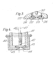
- Figures 4 and 5 show a generally similar arrangement, but here the fixed or floating valve plate 43 is mounted with its orifice on one axis, and the lower valve plate 44 is mounted on an annular member 45 which is rotatable about an axis 46 which is offset from the axis 47 through the orifices and valve plates 43 and 44.
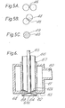
- rotation of the annulus 45 will cause rotational displacement of the orifices of the plates 43 and 44 relative to one another as can be seen in Figures 5A, 5B and 5C.
- the shaded area 48 and 49 in Figures 6B and 6C - show partial and complete overlap of the two orifices.
- a rod 41 with a cap 42 is again provided as in Figures 1, 2 and 3.
- Figure 6 shows a further modification.
- the construction of the means for moving the orifices relative to one another can be either as shown in Figures 1 to 3 or as in Figures 4 and 5.
- the product inlet 60 extends into the chamber 61 having a lower end wall 63 in which is located a fixed or floating valve plate 62.
- the other valve plate 64 as indicated above, be moved by any suitable means to effect the preadjustment of the flow passage through the orifices 62A,64A of the valve plates.
- a rod 65 similar to the plunger illustrated in Figures 1 to 3, which is axially aligned with the orifices through the valve plates, the lower end of the rod 65 being shaped to conform to the shape of the taper of the orifice in the upper valve plate 62.
- a hollow piston.66 is axially slidable so that its internal surface is in sliding contact with the external surface of the rod 65.
- a sleeve 67 is axially slidable with its inner surface in contact with the outer surface of the piston 66.
- the piston 66 and the sleeve 67 are raised, when the rod 65 has closed the orifices in the valve plates, so that a gap 68, 69 is provided below the sleeve and the piston.
- the sleeve 67 is then lowered, so that it contacts the plate or end wall 63, thus entrapping product, under pressure, below the piston and around the rod 65.
- the rod 65 is then raised and the piston 66 lowered together, so that the product is forced out, still under pressure, through the orifices.
- the volume which is discharged for each movement can be determined by suitable previous displacement upwardly of the piston 66.
- an accurately metered quartity of product can be discharged at each operation.
- the rod 65 is once again forced into the orifice abruptly to cut off the flow without disturbing the preadjustment of cross-section of the flow passage and also allowing constant pressure operation.
- FIG. 7 A further arrangement is shown in Figure 7, from which it will be seen that product inlet 71 leads into a chamber 72 within which is secured, in fixed position, a first valve plate 74, mounted in the holder provided with a peripheral O-ring seal 76.
- a second valve plate 73 is slidable with respect to, and in contact with, the first valve plate 74, on the upstream side thereof, that is near the interior of the chamber 72.
- the two valve plates 73 and 74 are provided with truncated conical tapered orifices 73A and 74p respectively.
- the body 75 of the valving arrangement has slidable in the vertical direction, as viewed in the drawing, a member 77, the vertical reciprocation of which is effected by a fluid pressure operated piston and cylinder arrangement (not shown).
- the member 77 carries a cam 78, the horizontal position of which can be adjusted by a screw 79 and a nut 80.
- the cam 78 has a ramp surface 81, between cooperating with a follower 81A, which itself carries a slide 81B upon which is mounted the second valve plate 73.
- the return spring 82 is provided to urge the follower 81A against the ramp 81.
- an O-ring seal 83 is provided around the slide 81B.
- Figure 8 shows an arrangement in which two orifices 73A and 74A do not communicate with one another at all.
- the arrangement of Figure 2A and 2B can be achieved by adjusting the screw 79 to move the ramp surface 81 of the cam 78 to the left by a greater or smaller amount.
- the fluid cylinder connected to member 77 is operated, and the cam is moved a suitable amount to move the valve plate by a larger amount to achieve the arrangement shown in Figure 8, so that no flow can take place.
- This arrangement thus, ensures an abrupt cut off of the flow.
- valve plates will re-assume their previous preadjustment.
Landscapes
- Engineering & Computer Science (AREA)
- Life Sciences & Earth Sciences (AREA)
- Chemical & Material Sciences (AREA)
- Food Science & Technology (AREA)
- Polymers & Plastics (AREA)
- General Engineering & Computer Science (AREA)
- Mechanical Engineering (AREA)
- Confectionery (AREA)
- Fluid-Damping Devices (AREA)
- Check Valves (AREA)
- Lift Valve (AREA)
- Compressor (AREA)
- Superconductors And Manufacturing Methods Therefor (AREA)
- Multiple-Way Valves (AREA)
Priority Applications (1)
| Application Number | Priority Date | Filing Date | Title |
|---|---|---|---|
| AT81300476T ATE12571T1 (de) | 1980-02-25 | 1981-02-04 | Absperrventilvorrichtung. |
Applications Claiming Priority (2)
| Application Number | Priority Date | Filing Date | Title |
|---|---|---|---|
| GB8006248 | 1980-02-25 | ||
| GB8006248A GB2070197A (en) | 1980-02-25 | 1980-02-25 | Valving arrangement |
Publications (3)
| Publication Number | Publication Date |
|---|---|
| EP0034884A2 true EP0034884A2 (de) | 1981-09-02 |
| EP0034884A3 EP0034884A3 (en) | 1982-08-25 |
| EP0034884B1 EP0034884B1 (de) | 1985-04-10 |
Family
ID=10511644
Family Applications (1)
| Application Number | Title | Priority Date | Filing Date |
|---|---|---|---|
| EP81300476A Expired EP0034884B1 (de) | 1980-02-25 | 1981-02-04 | Absperrventilvorrichtung |
Country Status (18)
| Country | Link |
|---|---|
| US (1) | US4384678A (de) |
| EP (1) | EP0034884B1 (de) |
| JP (1) | JPS56138581A (de) |
| KR (1) | KR840000896B1 (de) |
| AR (1) | AR224676A1 (de) |
| AT (1) | ATE12571T1 (de) |
| AU (1) | AU538350B2 (de) |
| BR (1) | BR8101019A (de) |
| DD (1) | DD156566A5 (de) |
| DE (1) | DE3169779D1 (de) |
| DK (1) | DK81381A (de) |
| ES (1) | ES499756A0 (de) |
| FI (1) | FI810556A7 (de) |
| GB (2) | GB2070197A (de) |
| IE (1) | IE50684B1 (de) |
| NO (1) | NO810628L (de) |
| NZ (1) | NZ196173A (de) |
| ZA (1) | ZA81786B (de) |
Cited By (3)
| Publication number | Priority date | Publication date | Assignee | Title |
|---|---|---|---|---|
| EP0106624A3 (en) * | 1982-10-13 | 1985-07-31 | Cadbury Limited | Method and apparatus for manufacturing a confection, a depositor for use in such a method and depositing apparatus |
| WO2016198659A1 (en) * | 2015-06-11 | 2016-12-15 | Nestec S.A. | Method, apparatus and nozzle for depositing |
| EP3888469A3 (de) * | 2021-07-12 | 2022-04-06 | Aasted ApS | Lebensmittelproduktionslinie, ablagevorrichtung und düsen für süsswarenartikel |
Families Citing this family (9)
| Publication number | Priority date | Publication date | Assignee | Title |
|---|---|---|---|---|
| JPS6025648B2 (ja) * | 1977-06-20 | 1985-06-19 | 理雄 安部 | ヘリカル・コニカル・スプリング・ロツク・ワツシヤ− |
| AT381571B (de) * | 1982-11-15 | 1986-11-10 | Oemv Ag | Einrichtung zum stufenweisen druckabbau bei der entspannung von insbesondere heissen gasen |
| GB8424268D0 (en) * | 1984-09-26 | 1984-10-31 | Wymbs Eng Ltd | Valve arrangement |
| US5423913A (en) * | 1991-10-30 | 1995-06-13 | Fontaine; Paul P. | Apparatus and method for control of metallic coating-weight by the use of gas knives |
| US6161785A (en) * | 1998-01-26 | 2000-12-19 | Charged Injection Corporation | Electrostatic atomizer based micro-burner for logistic fuels |
| EP1374692B1 (de) | 1999-04-22 | 2005-04-13 | APV Systems Limited | Konfektüberzugsmittel |
| DE60003056T2 (de) | 1999-10-22 | 2004-04-01 | Apv Systems Ltd. | Belüftungssystem für konditorwaren |
| PL2016837T3 (pl) * | 2007-07-20 | 2012-05-31 | Kraft Foods R & D Inc | Sposób wytwarzania produktu cukierniczego |
| EP2016836B1 (de) * | 2007-07-20 | 2016-07-20 | Kraft Foods R & D, Inc. | VERFAHREN ZUR HERSTELLUNG EINER SÜßSPEISE |
Family Cites Families (16)
| Publication number | Priority date | Publication date | Assignee | Title |
|---|---|---|---|---|
| US497903A (en) * | 1893-05-23 | Adjustable nozzle | ||
| FR340021A (fr) * | 1904-01-29 | 1904-06-24 | Alfred Koelliker | Pastilleuse perfectionnée |
| DE391116C (de) * | 1921-07-15 | 1924-02-28 | Anton Reiche A G | Vorrichtung zum Ab- und Einfuellen von mehr oder weniger dickfluessiger Masse, wie Schokolade, in Formen aus einem offenen Behaelter |
| US1802113A (en) * | 1925-08-10 | 1931-04-21 | Frederick W Intemann | Dispensing device for whipped cream and similar materials |
| GB303154A (en) * | 1927-12-29 | 1929-10-10 | Cornelis Gerardus Ebeli | Improvements in or relating to machines for filling moulds with chocolate or other thick fluid masses |
| FR74781E (fr) * | 1959-01-08 | 1961-01-16 | Maison H Humbert | Dispositif pour la fabrication continue en série d'objets tels que des pastilles de pâte de fruits |
| US3054534A (en) * | 1960-08-22 | 1962-09-18 | Sr Joseph G Vollmer | Ice cream dispenser |
| CH420498A (de) * | 1965-03-09 | 1966-09-15 | Concast Ag | Vorrichtung zum Verändern der Lage des Giessstrahles, insbesondere beim Stranggiessen |
| FR1526632A (fr) * | 1967-06-09 | 1968-05-24 | Maryland Cup Corp | Dispositif distributeur de liquides |
| DE1757807C3 (de) * | 1968-06-18 | 1978-05-03 | Veb Kombinat Nagema, Ddr 8045 Dresden | Vorrichtung zum gewichtsgleichen Abteilen und Gießen leichtfließender Massen |
| US3737328A (en) * | 1970-10-30 | 1973-06-05 | Grace W R & Co | Apparatus and method for preparing confectionery drops |
| US3807607A (en) * | 1970-12-05 | 1974-04-30 | Dagma Gmbh & Co | Dispensing of high-viscosity liquids |
| DE2128666A1 (en) * | 1971-06-09 | 1972-12-28 | Winkler & Dünnebier, Maschinenfabrik und Eisengießerei KG, 5450 Neuwied | Sugar casting machine - for multiple sweetmeat casting into moulds using hydraulic control system |
| DE2541419C3 (de) * | 1975-09-17 | 1978-06-08 | Mjoelkcentralen Arla, Ekonomisk Foerening, Stockholm | Vorrichtung zur Ausgabe eines verhältnismäßig dickflüssigen Produktes wie Schokolade oder dergleichen in vorgegebenen Portionen |
| US4100304A (en) * | 1977-05-04 | 1978-07-11 | Vroman Foods, Inc. | Method for producing and processing frozen confections |
| CH632420A5 (de) * | 1977-07-27 | 1982-10-15 | Oakes E T Ltd | Verfahren zur herstellung eines zellfoermigen erzeugnisses, und anwendung desselben zur herstellung eines erzeugnisses aus schokolade. |
-
1980
- 1980-02-25 GB GB8006248A patent/GB2070197A/en not_active Withdrawn
-
1981
- 1981-02-03 IE IE206/81A patent/IE50684B1/en unknown
- 1981-02-03 NZ NZ196173A patent/NZ196173A/en unknown
- 1981-02-04 AT AT81300476T patent/ATE12571T1/de not_active IP Right Cessation
- 1981-02-04 DE DE8181300476T patent/DE3169779D1/de not_active Expired
- 1981-02-04 GB GB8103380A patent/GB2070202B/en not_active Expired
- 1981-02-04 EP EP81300476A patent/EP0034884B1/de not_active Expired
- 1981-02-05 ZA ZA00810786A patent/ZA81786B/xx unknown
- 1981-02-20 US US06/236,599 patent/US4384678A/en not_active Expired - Fee Related
- 1981-02-20 BR BR8101019A patent/BR8101019A/pt unknown
- 1981-02-23 JP JP2535981A patent/JPS56138581A/ja active Pending
- 1981-02-24 DK DK81381A patent/DK81381A/da not_active Application Discontinuation
- 1981-02-24 AR AR284421A patent/AR224676A1/es active
- 1981-02-24 KR KR1019810000605A patent/KR840000896B1/ko not_active Expired
- 1981-02-24 FI FI810556A patent/FI810556A7/fi not_active Application Discontinuation
- 1981-02-24 ES ES499756A patent/ES499756A0/es active Granted
- 1981-02-24 NO NO810628A patent/NO810628L/no unknown
- 1981-02-24 AU AU67569/81A patent/AU538350B2/en not_active Ceased
- 1981-02-25 DD DD81227872A patent/DD156566A5/de unknown
Cited By (4)
| Publication number | Priority date | Publication date | Assignee | Title |
|---|---|---|---|---|
| EP0106624A3 (en) * | 1982-10-13 | 1985-07-31 | Cadbury Limited | Method and apparatus for manufacturing a confection, a depositor for use in such a method and depositing apparatus |
| US4637788A (en) * | 1982-10-13 | 1987-01-20 | Cadbury Limited | Apparatus for making a confection including a depositing means and conveyor carried molds |
| WO2016198659A1 (en) * | 2015-06-11 | 2016-12-15 | Nestec S.A. | Method, apparatus and nozzle for depositing |
| EP3888469A3 (de) * | 2021-07-12 | 2022-04-06 | Aasted ApS | Lebensmittelproduktionslinie, ablagevorrichtung und düsen für süsswarenartikel |
Also Published As
| Publication number | Publication date |
|---|---|
| GB2070202B (en) | 1983-08-10 |
| ATE12571T1 (de) | 1985-04-15 |
| AU6756981A (en) | 1981-09-03 |
| FI810556L (fi) | 1981-08-26 |
| ZA81786B (en) | 1982-03-31 |
| ES8207309A1 (es) | 1982-09-01 |
| JPS56138581A (en) | 1981-10-29 |
| EP0034884B1 (de) | 1985-04-10 |
| IE50684B1 (en) | 1986-06-11 |
| NO810628L (no) | 1981-08-26 |
| DK81381A (da) | 1981-08-26 |
| DE3169779D1 (en) | 1985-05-15 |
| KR840000896B1 (ko) | 1984-06-26 |
| US4384678A (en) | 1983-05-24 |
| DD156566A5 (de) | 1982-09-08 |
| AU538350B2 (en) | 1984-08-09 |
| ES499756A0 (es) | 1982-09-01 |
| AR224676A1 (es) | 1981-12-30 |
| KR830005595A (ko) | 1983-08-20 |
| EP0034884A3 (en) | 1982-08-25 |
| NZ196173A (en) | 1984-12-14 |
| IE810206L (en) | 1981-08-25 |
| GB2070197A (en) | 1981-09-03 |
| FI810556A7 (fi) | 1981-08-26 |
| BR8101019A (pt) | 1981-08-25 |
| GB2070202A (en) | 1981-09-03 |
Similar Documents
| Publication | Publication Date | Title |
|---|---|---|
| US4384678A (en) | Valving arrangement | |
| US4264020A (en) | Manual dispenser for pasty material held in a reservoir under pressure | |
| CA2100663C (en) | Valve actuator for a soft drink dispenser station | |
| DE3020122C2 (de) | Schaltungsanordung zum Zudosieren von gasförmigen oder flüssigen Stoffen, insbesondere physikalischen Treibmitteln, in eine fließfähige Schmelze aus thermoplastischem Kunststoff | |
| DE2306085A1 (de) | Nachfuellbare spruehvorrichtung | |
| US3878973A (en) | Metered dose dispenser | |
| AU4145997A (en) | Dispensing apparatus having improved dynamic range | |
| DE2555156A1 (de) | Hochdruck-mischkopf | |
| HK142193A (en) | Dispensing apparatus for metered quantities of pressurised fluid | |
| US4068829A (en) | Head for mixing and discharging at least two ingredients | |
| US4679711A (en) | Multi-orifice zero cavity nozzle dispenser | |
| US3972344A (en) | Valve for water sprinklers and the like | |
| US4132483A (en) | Molding machine with proportional dispensing | |
| US3861564A (en) | Product pressurizing dispenser including product flow cutoff | |
| US6073817A (en) | Pneumatically-actuated throttle valve for molten solder dispenser | |
| CA1337904C (en) | Sealless modular positive displacement dispenser | |
| EP0108952B1 (de) | Dosiervorrichtung zum Einspeisen von Flüssigkeiten in strömende Medien | |
| EP0173031A2 (de) | Anordnung zum Karbonisieren von Wasser | |
| WO2000023180A1 (de) | Ventileinrichtung | |
| CA2222927A1 (en) | Apparatus and method for dispensing fluid material | |
| EP0601215A1 (de) | Dosier-Entnahmevorrichtung | |
| US4741088A (en) | Method of making a delivery head for containers of substances to be nebulized having a break-up plastic insert integrally formed with the head | |
| US5779147A (en) | Dosing nozzle assembly and process for dosing liquid | |
| DE2852651A1 (de) | Vorrichtung zum fortlaufenden nacheinander austeilen gleicher portionen einer teigigen oder halbteigigen masse aus einem vorrat, aus welchen sie mit konstantem ausschank mittels einer mit konstanter drehbewegung in drehung gesetzten foerderschraube vorgeschoben wird | |
| EP0159681A2 (de) | Mehrkomponenten Proportionieranlage |
Legal Events
| Date | Code | Title | Description |
|---|---|---|---|
| PUAI | Public reference made under article 153(3) epc to a published international application that has entered the european phase |
Free format text: ORIGINAL CODE: 0009012 |
|
| AK | Designated contracting states |
Designated state(s): AT BE CH DE FR GB IT LU NL SE |
|
| PUAL | Search report despatched |
Free format text: ORIGINAL CODE: 0009013 |
|
| AK | Designated contracting states |
Designated state(s): AT BE CH DE FR GB IT LU NL SE |
|
| 17P | Request for examination filed |
Effective date: 19830224 |
|
| ITF | It: translation for a ep patent filed | ||
| GRAA | (expected) grant |
Free format text: ORIGINAL CODE: 0009210 |
|
| RAP1 | Party data changed (applicant data changed or rights of an application transferred) |
Owner name: SIMON-VICARS LIMITED |
|
| AK | Designated contracting states |
Designated state(s): AT BE CH DE FR GB IT LI LU NL SE |
|
| REF | Corresponds to: |
Ref document number: 12571 Country of ref document: AT Date of ref document: 19850415 Kind code of ref document: T |
|
| RBV | Designated contracting states (corrected) |
Designated state(s): AT BE CH DE FR IT LI LU NL SE |
|
| REF | Corresponds to: |
Ref document number: 3169779 Country of ref document: DE Date of ref document: 19850515 |
|
| ET | Fr: translation filed | ||
| PG25 | Lapsed in a contracting state [announced via postgrant information from national office to epo] |
Ref country code: AT Effective date: 19860204 |
|
| PG25 | Lapsed in a contracting state [announced via postgrant information from national office to epo] |
Ref country code: SE Effective date: 19860205 |
|
| PLBE | No opposition filed within time limit |
Free format text: ORIGINAL CODE: 0009261 |
|
| STAA | Information on the status of an ep patent application or granted ep patent |
Free format text: STATUS: NO OPPOSITION FILED WITHIN TIME LIMIT |
|
| PG25 | Lapsed in a contracting state [announced via postgrant information from national office to epo] |
Ref country code: LU Free format text: LAPSE BECAUSE OF NON-PAYMENT OF DUE FEES Effective date: 19860228 Ref country code: LI Effective date: 19860228 Ref country code: CH Effective date: 19860228 Ref country code: BE Effective date: 19860228 |
|
| 26N | No opposition filed | ||
| BERE | Be: lapsed |
Owner name: SIMON-VICARS LTD Effective date: 19860228 |
|
| GBPC | Gb: european patent ceased through non-payment of renewal fee | ||
| PG25 | Lapsed in a contracting state [announced via postgrant information from national office to epo] |
Ref country code: FR Free format text: LAPSE BECAUSE OF NON-PAYMENT OF DUE FEES Effective date: 19861031 |
|
| REG | Reference to a national code |
Ref country code: CH Ref legal event code: PL |
|
| PG25 | Lapsed in a contracting state [announced via postgrant information from national office to epo] |
Ref country code: DE Effective date: 19861101 |
|
| REG | Reference to a national code |
Ref country code: FR Ref legal event code: ST |
|
| PGFP | Annual fee paid to national office [announced via postgrant information from national office to epo] |
Ref country code: NL Payment date: 19870228 Year of fee payment: 7 |
|
| PG25 | Lapsed in a contracting state [announced via postgrant information from national office to epo] |
Ref country code: NL Effective date: 19880901 |
|
| NLV4 | Nl: lapsed or anulled due to non-payment of the annual fee | ||
| EUG | Se: european patent has lapsed |
Ref document number: 81300476.9 Effective date: 19861023 |