EP0034885A2 - Vorrichtung zur Banknotenausgabe mittels Kreditkarten - Google Patents
Vorrichtung zur Banknotenausgabe mittels Kreditkarten Download PDFInfo
- Publication number
- EP0034885A2 EP0034885A2 EP81300477A EP81300477A EP0034885A2 EP 0034885 A2 EP0034885 A2 EP 0034885A2 EP 81300477 A EP81300477 A EP 81300477A EP 81300477 A EP81300477 A EP 81300477A EP 0034885 A2 EP0034885 A2 EP 0034885A2
- Authority
- EP
- European Patent Office
- Prior art keywords
- control
- unit
- bank
- dispensing
- signal
- Prior art date
- Legal status (The legal status is an assumption and is not a legal conclusion. Google has not performed a legal analysis and makes no representation as to the accuracy of the status listed.)
- Granted
Links
Images


Classifications
-
- G—PHYSICS
- G07—CHECKING-DEVICES
- G07F—COIN-FREED OR LIKE APPARATUS
- G07F19/00—Complete banking systems; Coded card-freed arrangements adapted for dispensing or receiving monies or the like and posting such transactions to existing accounts, e.g. automatic teller machines
- G07F19/20—Automatic teller machines [ATMs]
- G07F19/202—Depositing operations within ATMs
-
- G—PHYSICS
- G07—CHECKING-DEVICES
- G07F—COIN-FREED OR LIKE APPARATUS
- G07F19/00—Complete banking systems; Coded card-freed arrangements adapted for dispensing or receiving monies or the like and posting such transactions to existing accounts, e.g. automatic teller machines
- G07F19/20—Automatic teller machines [ATMs]
Definitions
- This invention relates to apparatus for dispensing bank-notes under the control of credit cards, in which a control unit controls a dispensing device in response to a unit for comparing a number recorded on the card with an identification number entered by the customer.
- the dispensing device is enabled to dispense bank-notes solely by the control unit, which is connected to the dispensing device by connections which are easily accessible from the outside, especially if the control signal arrives from a remote central unit.
- These connections can therefore be relatively easily tampered with, because of which it is possible to generate improper activation signals or fraudulently invert such signals.
- This possibility is still greater in the case of bank-notes dispensing apparatus installed outside.
- Such apparatus are normally provided with a strong box which contains both the dispensing device and the comparison unit for the secret customer- identification number, but the control unit is generally outside the strong box, because of which its connection to the comparison unit and dispensing device is easily accessible.
- the object of the invention is to obviate the danger of fraud due to the accessibility of the connections between the dispensing device and the control unit.
- the apparatus comprises a central or control unit 10, for example a microprocessor, arranged to control a series of peripheral units.
- a reading and recording device 11 for a credit card adapted to receive the credit card in a slot 12 and to transfer it into a reading and recording zone.
- the credit card contains a read-only track carrying a set of identification data, and another reading and writing track carrying the accounting data which allow and record the withdrawal of a determined sum within a fixed period or cycle.
- the device 11 identifies the customer by combining, under the control of the central unit 10, the data read from the read-only track of the credit card with a secret identification number (PIN) which the customer enters on a keyboard 13 under the guide of information which the unit 10 displays on a display screen 14.
- PIN secret identification number
- the apparatus also comprises a bank-note dispensing unit 17, which comprises one or more drawers, each for containing the bank-notes of a corresponding denomination.
- a bank-note dispensing unit 17 which comprises one or more drawers, each for containing the bank-notes of a corresponding denomination.
- the unit 17 is controlled by the central unit 10 on the basis of the number executed on the keyboard, in such a manner as to withdraw a determined number of bank-notes of the various denominations and to collect them into a wad which is then presented to the customer at a slot 18 in the front panel of the apparatus.
- the central unit 10 controls the unit 11 such that it updates on the reading and writing track of the credit card the sum which can still be withdrawn within the given period, after which the unit 11 returns the credit card to the customer through the slot 12.
- the apparatus also comprises an envelope dispensing unit 22, which is operated under the control of the central unit 10 following the identification of the customer by the unit 11 on the basis of the credit card as seen heretofore, and on executing the required type of transaction on the keyboard.
- the customer can place bank-notes to be deposited inside the envelope dispensed in this manner. He then reinserts the envelope containing the bank-notes into an envelope collection unit 23, which stamps the envelope and feeds it to a deposit drawer 24 under the control of the central unit 10.
- the keyboard 13, the screen 14 and the slots for access to the unit 17 and to the devices 22 and 23 are protected by an anti-vandal slide-plate 24, (Fig 3) which is driven by a servomotor controlled by the central unit 10.
- the slide-plate 24 is normally closed and is opened only when a credit card is inserted into the slot 12 of the unit 11 and recognised as valid by the unit 11.
- the apparatus is arranged in a recess 26 in the wall of a bank, so as to be accessible by the customer directly from the outside.
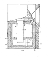
- the apparatus is contained in a metal cabinet 27 and comprises an armoured container in the form of a strong box 28 accessible to the bank's operator from the inside by way of an armoured door 29 (Fig 4).
- the strong box 28 contains the dispensing device 17, the slot 18 of which ( Figure 3) is disposed in a position corresponding with an aperture 31 in the top of the strong box 28.
- the strong box 28 also houses the deposit drawer 24, connected to the unit 23 by way of a slot 32 in the strong box 28 and a duct 33. Finally, the strong box 28 contains the customer identification unit 9, which is electrically connected directly to the device 17. The electrical supply cables for the units 9 and 17 and the control cables between these and the central unit 10 passes through a hole 34 ( Figure 3) in the strong box 28.
- the central unit, together with the power supply unit 35, the unit 11 and the keyboard 13, the screen 14, the units 22 and 23 and other devices not illustrated are located outside the strong box 28, because of which the weight and thus the cost of the apparatus is reduced to a minimum.
- the identification unit 9 comprises a digitising circuit 36 ( Figure 2), which is connected by way of a serial interface 37 to the central unit 10, to receive the account number read by the unit 11 from the read-only track of the credit card.
- This digitising is carried out under the control of one or more algorithms normally recorded in a memory 38 and selectively extractable under the control of the central unit 10.
- the identification unit 9 also comprises a comparison device or circuit 39 arranged to compare the number digitised by the circuit 36 with the secret customer identification number, commonly known as a PIN. This number, when entered on the keyboard 13, is fed to the circuit 39 by the central unit 10 by way of an interface 41.
- a comparison device or circuit 39 arranged to compare the number digitised by the circuit 36 with the secret customer identification number, commonly known as a PIN. This number, when entered on the keyboard 13, is fed to the circuit 39 by the central unit 10 by way of an interface 41.
- the circuit 39 is arranged to emit a signal OK if the result of the comparison is positive, whereas in all other cases it emits a signal N. These two signals are fed through two corresponding electrical conductors 40 and 48 to the central unit 10. This, in response to the signal OK, allows the customer to set the amount to be withdrawn on the keyboard 13. The central unit 10 now compares the value of this amount with the value read by the unit 11 from the reading and writing track. If the result of this comparison is also positive, the central unit 10 feeds the order for the withdrawal of a corresponding number of bank-notes through a conductor 42.
- the conductor 42 is connected to a logic circuit 43 for controlling a drive motor 44 for the dispensing device 17.
- the logic circuit 43 is arranged to be inhibited by inhibition means disposed in the strong box 28 and constituted by a flip-flop 46, which can be set by the signal N emitted by the circuit 39 through a conductor 48' inside the strong box 28, and reset by the signal OK of the circuit 39 through a conductor 40' also inside the strong box 28.
- the flip-flop 46 can also be set at least by a signal D generated by a sensor for the wad of bank-notes and indicating the end of a withdrawal operation.
- the flip-flop 46 is set by a signal A which is generated at the beginning when the apparatus is connected to the mains after an interruption for any reason.
- the flip-flop 45 When set, the flip-flop 45 inhibits the logic circuit 43 by way of a conductor 47, so that the dispensing device 17 is directly blocked.
- the flip-flop 46 is normally set, because of which the logic circuit 43 is inhibited. It is reset in order to activate the circuit.43 only by the signal OK following a positive comparison carried out by the circuit 39.
- the signal OK enables the central unit 10 to continue the transaction and to feed the dispensing commands to the circuit 43 through the conductor 42.
- the signal When the end of the dispensing operation is signalled by the device 17, the signal again sets the flip-flop 46, so that the circuit 43 is again inhibited.
Landscapes
- Business, Economics & Management (AREA)
- Accounting & Taxation (AREA)
- Finance (AREA)
- Physics & Mathematics (AREA)
- General Physics & Mathematics (AREA)
- Financial Or Insurance-Related Operations Such As Payment And Settlement (AREA)
- Control Of Vending Devices And Auxiliary Devices For Vending Devices (AREA)
Applications Claiming Priority (2)
| Application Number | Priority Date | Filing Date | Title |
|---|---|---|---|
| IT6718980 | 1980-02-08 | ||
| IT67189/80A IT1128032B (it) | 1980-02-08 | 1980-02-08 | Apparecchiatura per la dispensazione di banconote sotto il controllo di carte di credito |
Publications (3)
| Publication Number | Publication Date |
|---|---|
| EP0034885A2 true EP0034885A2 (de) | 1981-09-02 |
| EP0034885A3 EP0034885A3 (en) | 1985-09-25 |
| EP0034885B1 EP0034885B1 (de) | 1987-11-19 |
Family
ID=11300331
Family Applications (1)
| Application Number | Title | Priority Date | Filing Date |
|---|---|---|---|
| EP81300477A Expired EP0034885B1 (de) | 1980-02-08 | 1981-02-04 | Vorrichtung zur Banknotenausgabe mittels Kreditkarten |
Country Status (4)
| Country | Link |
|---|---|
| EP (1) | EP0034885B1 (de) |
| JP (1) | JPS56123068A (de) |
| DE (1) | DE3176539D1 (de) |
| IT (1) | IT1128032B (de) |
Cited By (1)
| Publication number | Priority date | Publication date | Assignee | Title |
|---|---|---|---|---|
| EP1544818A1 (de) * | 2003-12-18 | 2005-06-22 | Axalto S.A. | Gesichertes Endgerät |
Family Cites Families (4)
| Publication number | Priority date | Publication date | Assignee | Title |
|---|---|---|---|---|
| JPS5543138B1 (de) * | 1969-04-26 | 1980-11-05 | ||
| JPS50108995A (de) * | 1974-02-01 | 1975-08-27 | ||
| US4075460A (en) * | 1975-11-28 | 1978-02-21 | Incoterm Corporation | Cash dispensing system |
| GB1561482A (en) * | 1976-11-18 | 1980-02-20 | Ibm | Protection of data processing system against unauthorised programmes |
-
1980
- 1980-02-08 IT IT67189/80A patent/IT1128032B/it active
-
1981
- 1981-02-04 EP EP81300477A patent/EP0034885B1/de not_active Expired
- 1981-02-04 DE DE8181300477T patent/DE3176539D1/de not_active Expired
- 1981-02-09 JP JP1792981A patent/JPS56123068A/ja active Granted
Cited By (3)
| Publication number | Priority date | Publication date | Assignee | Title |
|---|---|---|---|---|
| EP1544818A1 (de) * | 2003-12-18 | 2005-06-22 | Axalto S.A. | Gesichertes Endgerät |
| WO2005062266A1 (fr) * | 2003-12-18 | 2005-07-07 | Axalto Sa | Terminal securise |
| US7757102B2 (en) | 2003-12-18 | 2010-07-13 | Axalto Sa | Secure terminal |
Also Published As
| Publication number | Publication date |
|---|---|
| JPS641826B2 (de) | 1989-01-12 |
| IT8067189A0 (it) | 1980-02-08 |
| EP0034885A3 (en) | 1985-09-25 |
| EP0034885B1 (de) | 1987-11-19 |
| DE3176539D1 (en) | 1987-12-23 |
| JPS56123068A (en) | 1981-09-26 |
| IT1128032B (it) | 1986-05-28 |
Similar Documents
| Publication | Publication Date | Title |
|---|---|---|
| EP1045351B2 (de) | Geldverarbeitungsmaschine mit Anschluss für periphere Geräte | |
| US5489014A (en) | Apparatus for checking coins and reading cards in an article vending machine | |
| US5791449A (en) | Bezel for a vending machine | |
| US4778983A (en) | Automatic vending machine | |
| EP0146812A2 (de) | Automatische Selbstbedienungsvorrichtung und -verfahren | |
| US5641050A (en) | Dispensing machine with data card scanner apparatus and enhanced features | |
| US6427998B1 (en) | Replenishment arrangements for automated teller machines | |
| EP0034885B1 (de) | Vorrichtung zur Banknotenausgabe mittels Kreditkarten | |
| US5377809A (en) | Coin control systems for automatic machines | |
| KR100295890B1 (ko) | 주차요금 자동정산기 | |
| KR920004774B1 (ko) | 자동식 금전거래 장치 | |
| JPH0634859B2 (ja) | 遊技店における遊技媒体貸出機構 | |
| AU772756B2 (en) | System for the automatic withdrawal and deposit of banknotes | |
| JPH0652403A (ja) | 入出金装置 | |
| JP2000140395A (ja) | デ―タ記憶媒体処理装置 | |
| JP3035253U (ja) | カード自動登録発券装置とこのカード自動登録発券装置を用いたカード自動販売装置 | |
| EP0612045A1 (de) | Einführen von münzen in münzprüfsysteme von automaten | |
| JP2001266229A (ja) | 自動販売機 | |
| JPS6384578A (ja) | パチンコカ−ドシステムのカ−ド発行機 | |
| ES2011191A6 (es) | Sistema de cambio automatico de divisas. | |
| JPH07282323A (ja) | 自動スマートカード装置 | |
| KR20190097401A (ko) | 티켓발행기 | |
| JPH01276292A (ja) | 自動取引装置 | |
| JPS63188290A (ja) | 自動販売機システム | |
| JPS6246394A (ja) | 入出金取扱装置 |
Legal Events
| Date | Code | Title | Description |
|---|---|---|---|
| PUAI | Public reference made under article 153(3) epc to a published international application that has entered the european phase |
Free format text: ORIGINAL CODE: 0009012 |
|
| AK | Designated contracting states |
Designated state(s): DE FR GB NL SE |
|
| 17P | Request for examination filed |
Effective date: 19811019 |
|
| PUAL | Search report despatched |
Free format text: ORIGINAL CODE: 0009013 |
|
| AK | Designated contracting states |
Designated state(s): DE FR GB NL SE |
|
| 17Q | First examination report despatched |
Effective date: 19861008 |
|
| GRAA | (expected) grant |
Free format text: ORIGINAL CODE: 0009210 |
|
| AK | Designated contracting states |
Kind code of ref document: B1 Designated state(s): DE FR GB NL SE |
|
| PG25 | Lapsed in a contracting state [announced via postgrant information from national office to epo] |
Ref country code: NL Effective date: 19871119 |
|
| PG25 | Lapsed in a contracting state [announced via postgrant information from national office to epo] |
Ref country code: SE Effective date: 19871130 |
|
| REF | Corresponds to: |
Ref document number: 3176539 Country of ref document: DE Date of ref document: 19871223 |
|
| ET | Fr: translation filed | ||
| NLV1 | Nl: lapsed or annulled due to failure to fulfill the requirements of art. 29p and 29m of the patents act | ||
| PLBE | No opposition filed within time limit |
Free format text: ORIGINAL CODE: 0009261 |
|
| STAA | Information on the status of an ep patent application or granted ep patent |
Free format text: STATUS: NO OPPOSITION FILED WITHIN TIME LIMIT |
|
| 26N | No opposition filed | ||
| REG | Reference to a national code |
Ref country code: GB Ref legal event code: 732E |
|
| REG | Reference to a national code |
Ref country code: FR Ref legal event code: TP |
|
| PGFP | Annual fee paid to national office [announced via postgrant information from national office to epo] |
Ref country code: GB Payment date: 20000202 Year of fee payment: 20 |
|
| PGFP | Annual fee paid to national office [announced via postgrant information from national office to epo] |
Ref country code: DE Payment date: 20000207 Year of fee payment: 20 |
|
| PGFP | Annual fee paid to national office [announced via postgrant information from national office to epo] |
Ref country code: FR Payment date: 20000210 Year of fee payment: 20 |
|
| PG25 | Lapsed in a contracting state [announced via postgrant information from national office to epo] |
Ref country code: GB Free format text: LAPSE BECAUSE OF EXPIRATION OF PROTECTION Effective date: 20010203 |
|
| REG | Reference to a national code |
Ref country code: GB Ref legal event code: PE20 Effective date: 20010203 |