EP0034955A1 - Zündspule für Verbrennungsmotoren - Google Patents
Zündspule für Verbrennungsmotoren Download PDFInfo
- Publication number
- EP0034955A1 EP0034955A1 EP81400073A EP81400073A EP0034955A1 EP 0034955 A1 EP0034955 A1 EP 0034955A1 EP 81400073 A EP81400073 A EP 81400073A EP 81400073 A EP81400073 A EP 81400073A EP 0034955 A1 EP0034955 A1 EP 0034955A1
- Authority
- EP
- European Patent Office
- Prior art keywords
- branch
- permanent magnet
- ignition coil
- branches
- circuit
- Prior art date
- Legal status (The legal status is an assumption and is not a legal conclusion. Google has not performed a legal analysis and makes no representation as to the accuracy of the status listed.)
- Granted
Links
- 238000002485 combustion reaction Methods 0.000 title claims abstract description 4
- 238000004804 winding Methods 0.000 claims abstract description 34
- 230000005291 magnetic effect Effects 0.000 claims abstract description 33
- 230000001154 acute effect Effects 0.000 claims abstract description 5
- 238000003475 lamination Methods 0.000 abstract 1
- 229910052751 metal Inorganic materials 0.000 abstract 1
- 230000004907 flux Effects 0.000 description 10
- 230000005347 demagnetization Effects 0.000 description 4
- 238000004519 manufacturing process Methods 0.000 description 4
- 238000009792 diffusion process Methods 0.000 description 2
- RYGMFSIKBFXOCR-UHFFFAOYSA-N Copper Chemical compound [Cu] RYGMFSIKBFXOCR-UHFFFAOYSA-N 0.000 description 1
- 241000826860 Trapezium Species 0.000 description 1
- 230000001143 conditioned effect Effects 0.000 description 1
- 229910052802 copper Inorganic materials 0.000 description 1
- 239000010949 copper Substances 0.000 description 1
- 230000001419 dependent effect Effects 0.000 description 1
- 230000005294 ferromagnetic effect Effects 0.000 description 1
Images

Classifications
-
- H—ELECTRICITY
- H01—ELECTRIC ELEMENTS
- H01F—MAGNETS; INDUCTANCES; TRANSFORMERS; SELECTION OF MATERIALS FOR THEIR MAGNETIC PROPERTIES
- H01F3/00—Cores, Yokes, or armatures
- H01F3/10—Composite arrangements of magnetic circuits
-
- H—ELECTRICITY
- H01—ELECTRIC ELEMENTS
- H01F—MAGNETS; INDUCTANCES; TRANSFORMERS; SELECTION OF MATERIALS FOR THEIR MAGNETIC PROPERTIES
- H01F29/00—Variable transformers or inductances not covered by group H01F21/00
- H01F29/14—Variable transformers or inductances not covered by group H01F21/00 with variable magnetic bias
- H01F29/146—Constructional details
-
- H—ELECTRICITY
- H01—ELECTRIC ELEMENTS
- H01F—MAGNETS; INDUCTANCES; TRANSFORMERS; SELECTION OF MATERIALS FOR THEIR MAGNETIC PROPERTIES
- H01F38/00—Adaptations of transformers or inductances for specific applications or functions
- H01F38/12—Ignition, e.g. for IC engines
Definitions
- the present invention relates to an ignition coil for an internal combustion engine, in particular for a motor vehicle, coil comprising a closed magnetic circuit made up of a plurality of sheets, magnetic circuit in which is arranged in one of the permanent branches, a winding primary and a secondary winding surrounding another of the branches.
- a closed magnetic circuit made up of a plurality of sheets, magnetic circuit in which is arranged in one of the permanent branches, a winding primary and a secondary winding surrounding another of the branches.
- An embodiment of a coil with a closed magnetic circuit is known, embodiment, in which a permanent magnet is arranged perpendicular to the flux flowing in the circuit, the permanent magnet being magnetized in the direction of its thickness so that the the magnetic flux it generates is opposite to the flux produced by the primary winding when it is supplied.
- This permanent magnet is located in the branch opposite to the branch surrounded by the primary and secondary windings.
- One of the drawbacks of this circuit consisting of two U-shaped parts arranged facing each other, is that the dimensions of the permanent magnet, apart from its thickness, are a function of the section of the magnetic circuit.
- This quality which is involved in the reluctance of the circuit is dependent on the differences in thickness of the permanent magnet disposed opposite the branch surrounding the windings, which differences in thickness are inherent in any mass production.
- an ignition coil comprising a magnetic circuit, consisting of a plurality of sheets, and a permanent magnet disposed in one of the branches of said circuit, characterized in that that said circuit comprises, at least, a magnetic seal disposed along a plane forming an acute angle ⁇ with the plane of the faces of the permanent magnet adjacent to said circuit.
- the branch on which the primary winding and the secondary winding are arranged is of thickness less than the thickness of the other branches of the magnetic circuit.
- At least one magnetic seal is placed at one end of the branch surrounded by the primary and secondary windings.
- a fraction of the sheets, constituting the half-branches covers on both sides of the windings, the ends of the branch on which the windings are arranged.
- a magnetic circuit of this kind is known, in particular, from French patent application No. 72,02568 of 26.1.1972.
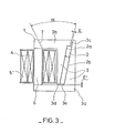
- a second embodiment of the ignition coil according to the invention is characterized in that one of the half-branches, constituting the branch in which the magnet is arranged, is provided at one of its ends, d 'A spoiler whose depth creates an air gap E, of predetermined value, between the two half-branches, which air gap E is located in the extension of the permanent magnet at one of its faces.
- Said circuif is also characterized in that another air gap E ', of predetermined value, is created between the edge of the sheets which constitute the small base of the rectangular trapezium of the portion of one of the half-branches adjacent to the permanent magnet and the song of the sheets of the other half-branch.
- a primary winding 4 and a secondary winding 5 surround the branch 6 which branch 6 is in this embodiment, consisting of a fraction of the sheets constituting the half-branch 3a, forming with the half-branch 3 ⁇ the branch 3.
- the thickness E ′ of branch 6 (see FIG. 2) is, in this embodiment less than twice the thickness E of branch 3.
- a magnetic seal 7 (see Figure 1) is provided at one end of the branch 6, which seal 7 is arranged in a plane forming an acute angle ⁇ with the plane of the adjacent faces 2a and 2b of the permanent magnet 2 to the half branches 3a and 3b.
- the half-branches 3a and 3b are made up of sheets of unequal lengths, so that a fraction of these sheets covers, on either side of the primary 4 and secondary 5 windings, the ends of the branch 6.
- this magnetic circuit eliminates the drawbacks cited in the prior art, by the fact that a large surface permanent magnet is provided in a magnetic circuit whose weight and size have been reduced to a minimum, compatible with the performance of the ignition coil.
- the large thickness E of the half-branches in which the permanent magnet is placed allows a significant reduction in the perimeter of the magnetic circuit and, correspondingly, a reduced size of the ignition coil.
- the magnetic seal located at one end of the branch surrounded by the primary and secondary windings, and forming an acute angle ⁇ with the plane of the faces adjacent to the permanent magnet absorbs the thickness differences of the permanent magnet due to manufacturing tolerances and also the cutting tolerances of the sheets constituting the magnetic circuit.
- This first embodiment has the drawback, however, that the flow reversal created in the branch surrounded by the primary and secondary windings by the current flowing in the primary winding requires the use of a magnet having a very coercive field. high so as to avoid demagnetization when the flux is reversed.
- the second embodiment of the magnetic circuit according to the invention aims to remedy this drawback.
- an air gap E of predetermined value is created between the half-branch 3a and the half-branch 3b by a spoiler 3c forming a projection at one of the ends of the half-branch 3b.
- the air gap E is located in the extension of the magnet 2 at its face 2b,
- Another air gap E ' is created between the edge of the sheets, of the half-branch 3b, constituting the small base 3d, of the portion, of said half-branch, having a view from above of the appearance d 'a rectangular trapezoid and the third song of the sheets of the half-branch 3a.
- the ignition coil may, depending on the performance required, such as for example a strong choke, have a magnetic circuit comprising either the air gap E or the air gap E ', or else comprise both the air gaps E and E'.
- the particular configuration of the magnetic circuit, according to this second embodiment ensures that despite the use for reasons of economy and supply, permanent magnets of large surface area and low coercive field, the weight and size of the ignition coil have been reduced to the maximum compatible with the required performance.
Landscapes
- Engineering & Computer Science (AREA)
- Power Engineering (AREA)
- Chemical & Material Sciences (AREA)
- Composite Materials (AREA)
- Ignition Installations For Internal Combustion Engines (AREA)
Applications Claiming Priority (4)
| Application Number | Priority Date | Filing Date | Title |
|---|---|---|---|
| FR8003653A FR2476218A1 (fr) | 1980-02-20 | 1980-02-20 | Bobine d'allumage pour moteurs a combustion interne |
| FR8003653 | 1980-02-20 | ||
| FR8009742A FR2481753A2 (fr) | 1980-04-30 | 1980-04-30 | Bobine d'allumage pour moteurs a combustion interne |
| FR8009742 | 1980-04-30 |
Publications (2)
| Publication Number | Publication Date |
|---|---|
| EP0034955A1 true EP0034955A1 (de) | 1981-09-02 |
| EP0034955B1 EP0034955B1 (de) | 1984-10-24 |
Family
ID=26221613
Family Applications (1)
| Application Number | Title | Priority Date | Filing Date |
|---|---|---|---|
| EP81400073A Expired EP0034955B1 (de) | 1980-02-20 | 1981-01-21 | Zündspule für Verbrennungsmotoren |
Country Status (3)
| Country | Link |
|---|---|
| EP (1) | EP0034955B1 (de) |
| DE (1) | DE3166748D1 (de) |
| ES (1) | ES499553A0 (de) |
Cited By (9)
| Publication number | Priority date | Publication date | Assignee | Title |
|---|---|---|---|---|
| EP0335142A1 (de) * | 1988-03-29 | 1989-10-04 | VOGT electronic Aktiengesellschaft | Schaltnetztransformator |
| FR2778490A1 (fr) * | 1998-05-11 | 1999-11-12 | Sagem | Bobine d'allumage pour moteur a combustion interne |
| EP1174595A1 (de) * | 2000-07-18 | 2002-01-23 | Peugeot Citroen Automobiles SA | Ventilaktuator in einer Brennkraftmaschine |
| EP1174596A1 (de) * | 2000-07-20 | 2002-01-23 | Peugeot Citroen Automobiles SA | Elektromagnetischer Hubventilaktuator in einer Brennkraftmaschine |
| FR2819623A1 (fr) * | 2001-01-17 | 2002-07-19 | Sagem | Bobine d'allumage pour moteur a combustion interne |
| DE10159112A1 (de) * | 2001-12-01 | 2003-06-18 | Hella Kg Hueck & Co | Zündtransformator für eine Gasentladungslampe in einem Kraftfahrzeug |
| FR2839580A1 (fr) * | 2002-05-10 | 2003-11-14 | Johnson Contr Automotive Elect | Bobine d'allumage a aimant permanent a court-circuit magnetique |
| EP2001028A1 (de) * | 2007-06-08 | 2008-12-10 | ABB Oy | Schutz permanenter Magneten in einem Gleichstrominduktor |
| WO2011159406A1 (en) * | 2010-06-15 | 2011-12-22 | Federal-Mogul Ignition Company | Ignition coil with energy storage and transformation |
Citations (1)
| Publication number | Priority date | Publication date | Assignee | Title |
|---|---|---|---|---|
| FR2168919A3 (de) * | 1972-01-26 | 1973-09-07 | Ducellier & Cie |
Family Cites Families (5)
| Publication number | Priority date | Publication date | Assignee | Title |
|---|---|---|---|---|
| NL76967C (de) * | 1951-04-23 | |||
| NL79888C (de) * | 1951-04-23 | |||
| FR66586E (fr) * | 1954-06-16 | 1957-04-16 | App Marchal Soc D Expl Const D | Transformateur dit <<bobine>> d'allumage |
| DE1464202A1 (de) * | 1962-02-23 | 1969-05-22 | Licentia Gmbh | Permanentvormagnetisiertes induktives Element |
| DE2226289A1 (de) * | 1971-05-11 | 1973-01-04 | Tdk Electronics Co Ltd | Vormagnetisierter magnetkern |
-
1981
- 1981-01-21 EP EP81400073A patent/EP0034955B1/de not_active Expired
- 1981-01-21 DE DE8181400073T patent/DE3166748D1/de not_active Expired
- 1981-02-18 ES ES499553A patent/ES499553A0/es active Granted
Patent Citations (1)
| Publication number | Priority date | Publication date | Assignee | Title |
|---|---|---|---|---|
| FR2168919A3 (de) * | 1972-01-26 | 1973-09-07 | Ducellier & Cie |
Cited By (15)
| Publication number | Priority date | Publication date | Assignee | Title |
|---|---|---|---|---|
| EP0335142A1 (de) * | 1988-03-29 | 1989-10-04 | VOGT electronic Aktiengesellschaft | Schaltnetztransformator |
| FR2778490A1 (fr) * | 1998-05-11 | 1999-11-12 | Sagem | Bobine d'allumage pour moteur a combustion interne |
| EP1174595A1 (de) * | 2000-07-18 | 2002-01-23 | Peugeot Citroen Automobiles SA | Ventilaktuator in einer Brennkraftmaschine |
| FR2812024A1 (fr) * | 2000-07-18 | 2002-01-25 | Peugeot Citroen Automobiles Sa | Actionneur de soupapes de moteurs a combustion interne |
| EP1174596A1 (de) * | 2000-07-20 | 2002-01-23 | Peugeot Citroen Automobiles SA | Elektromagnetischer Hubventilaktuator in einer Brennkraftmaschine |
| FR2812025A1 (fr) * | 2000-07-20 | 2002-01-25 | Peugeot Citroen Automobiles Sa | Actionneur electromagnetique de soupape de moteur a combustion interne |
| FR2819623A1 (fr) * | 2001-01-17 | 2002-07-19 | Sagem | Bobine d'allumage pour moteur a combustion interne |
| DE10159112A1 (de) * | 2001-12-01 | 2003-06-18 | Hella Kg Hueck & Co | Zündtransformator für eine Gasentladungslampe in einem Kraftfahrzeug |
| FR2839580A1 (fr) * | 2002-05-10 | 2003-11-14 | Johnson Contr Automotive Elect | Bobine d'allumage a aimant permanent a court-circuit magnetique |
| EP2001028A1 (de) * | 2007-06-08 | 2008-12-10 | ABB Oy | Schutz permanenter Magneten in einem Gleichstrominduktor |
| US8035470B2 (en) | 2007-06-08 | 2011-10-11 | Abb Oy | Protection of permanent magnets in a DC-inductor |
| CN101364472B (zh) * | 2007-06-08 | 2011-12-14 | Abb有限公司 | 直流感应器 |
| WO2011159406A1 (en) * | 2010-06-15 | 2011-12-22 | Federal-Mogul Ignition Company | Ignition coil with energy storage and transformation |
| US8289117B2 (en) | 2010-06-15 | 2012-10-16 | Federal-Mogul Corporation | Ignition coil with energy storage and transformation |
| CN102939635A (zh) * | 2010-06-15 | 2013-02-20 | 费德罗-莫格尔点火公司 | 用于能量储存和转换的点火线圈 |
Also Published As
| Publication number | Publication date |
|---|---|
| DE3166748D1 (en) | 1984-11-29 |
| EP0034955B1 (de) | 1984-10-24 |
| ES8200744A1 (es) | 1981-12-01 |
| ES499553A0 (es) | 1981-12-01 |
Similar Documents
| Publication | Publication Date | Title |
|---|---|---|
| EP0429625B1 (de) | Einphasiges elektromagnetisches betätigungsgerät mit geringem raumbedarf | |
| EP0034955B1 (de) | Zündspule für Verbrennungsmotoren | |
| EP0118454B1 (de) | Zündspule für verbennungsmotoren | |
| EP0829129A1 (de) | Elektromagnetischen betätiger mit mindenstens zwei stabile stellungen durch magnetische verriegelung | |
| FR2913142A1 (fr) | Actionneur electromagnetique hybride. | |
| FR2518840A1 (fr) | Systeme de champ d'un moteur a courant continu du type a aimant | |
| FR2583210A1 (fr) | Dispositif d'actionnement electromagnetique | |
| EP1082804A1 (de) | Rotierende maschine mit verbesserter erregung | |
| FR2574880A1 (fr) | Systeme formant butee magnetique axiale pour machine tournante | |
| FR2636480A1 (fr) | Moteur synchrone a aimants permanents | |
| CH643680A5 (fr) | Electro-aimant pour frein. | |
| WO1989012346A1 (fr) | Moteur electrique synchrone di- ou polyphase a rotor en forme de disque | |
| EP3221947A1 (de) | Elektrische maschine mit stator mit hohlräumen zur verwendung in einem kraftfahrzeug | |
| FR2476218A1 (fr) | Bobine d'allumage pour moteurs a combustion interne | |
| EP0043744B1 (de) | Zündspule für Brennkraftmaschine | |
| CH672566A5 (de) | ||
| FR2481753A2 (fr) | Bobine d'allumage pour moteurs a combustion interne | |
| EP0072266B1 (de) | Verfahren zur Erzeugung einer Spule mit geschlossenem magnetischem Kreis und einem Dauermagnet für die Zündung von Brennkraftmaschinen | |
| EP3229348B1 (de) | Rotor für eine elektrische maschine | |
| EP3939151B1 (de) | Elektromagnetische vorrichtung | |
| FR2695267A1 (fr) | Stator de machine tournante électrique à aimants permanents, notamment pour démarreur. | |
| FR2808116A1 (fr) | Dispositif comprenant au moins un electroaimant | |
| FR2818001A1 (fr) | Bobine d'allumage a entrefer optimise | |
| FR2617343A1 (fr) | Pole inducteur a aimant permanent, et stator de machine tournante electrique pourvu de tels poles | |
| FR2706069A1 (fr) | Bobine d'allumage pour moteur à combustion interne. |
Legal Events
| Date | Code | Title | Description |
|---|---|---|---|
| PUAI | Public reference made under article 153(3) epc to a published international application that has entered the european phase |
Free format text: ORIGINAL CODE: 0009012 |
|
| AK | Designated contracting states |
Designated state(s): DE GB IT SE |
|
| 17P | Request for examination filed |
Effective date: 19810925 |
|
| ITF | It: translation for a ep patent filed | ||
| GRAA | (expected) grant |
Free format text: ORIGINAL CODE: 0009210 |
|
| AK | Designated contracting states |
Designated state(s): DE GB IT SE |
|
| PG25 | Lapsed in a contracting state [announced via postgrant information from national office to epo] |
Ref country code: SE Effective date: 19841024 |
|
| REF | Corresponds to: |
Ref document number: 3166748 Country of ref document: DE Date of ref document: 19841129 |
|
| PLBE | No opposition filed within time limit |
Free format text: ORIGINAL CODE: 0009261 |
|
| STAA | Information on the status of an ep patent application or granted ep patent |
Free format text: STATUS: NO OPPOSITION FILED WITHIN TIME LIMIT |
|
| 26N | No opposition filed | ||
| ITTA | It: last paid annual fee | ||
| PGFP | Annual fee paid to national office [announced via postgrant information from national office to epo] |
Ref country code: DE Payment date: 19991228 Year of fee payment: 20 |
|
| PGFP | Annual fee paid to national office [announced via postgrant information from national office to epo] |
Ref country code: GB Payment date: 20000114 Year of fee payment: 20 |
|
| PG25 | Lapsed in a contracting state [announced via postgrant information from national office to epo] |
Ref country code: GB Free format text: LAPSE BECAUSE OF EXPIRATION OF PROTECTION Effective date: 20010120 |
|
| REG | Reference to a national code |
Ref country code: GB Ref legal event code: PE20 Effective date: 20010120 |