EP0034958A2 - Motor mit Drehkolben, die eine periodisch veränderliche Geschwindigkeit haben, und Antriebsmitteln - Google Patents
Motor mit Drehkolben, die eine periodisch veränderliche Geschwindigkeit haben, und Antriebsmitteln Download PDFInfo
- Publication number
- EP0034958A2 EP0034958A2 EP81400130A EP81400130A EP0034958A2 EP 0034958 A2 EP0034958 A2 EP 0034958A2 EP 81400130 A EP81400130 A EP 81400130A EP 81400130 A EP81400130 A EP 81400130A EP 0034958 A2 EP0034958 A2 EP 0034958A2
- Authority
- EP
- European Patent Office
- Prior art keywords
- pistons
- rotary
- crown
- casing
- arms
- Prior art date
- Legal status (The legal status is an assumption and is not a legal conclusion. Google has not performed a legal analysis and makes no representation as to the accuracy of the status listed.)
- Granted
Links
Images

Classifications
-
- F—MECHANICAL ENGINEERING; LIGHTING; HEATING; WEAPONS; BLASTING
- F01—MACHINES OR ENGINES IN GENERAL; ENGINE PLANTS IN GENERAL; STEAM ENGINES
- F01C—ROTARY-PISTON OR OSCILLATING-PISTON MACHINES OR ENGINES
- F01C1/00—Rotary-piston machines or engines
- F01C1/02—Rotary-piston machines or engines of arcuate-engagement type, i.e. with circular translatory movement of co-operating members, each member having the same number of teeth or tooth-equivalents
- F01C1/063—Rotary-piston machines or engines of arcuate-engagement type, i.e. with circular translatory movement of co-operating members, each member having the same number of teeth or tooth-equivalents with coaxially-mounted members having continuously-changing circumferential spacing between them
- F01C1/07—Rotary-piston machines or engines of arcuate-engagement type, i.e. with circular translatory movement of co-operating members, each member having the same number of teeth or tooth-equivalents with coaxially-mounted members having continuously-changing circumferential spacing between them having crankshaft-and-connecting-rod type drive
-
- F—MECHANICAL ENGINEERING; LIGHTING; HEATING; WEAPONS; BLASTING
- F02—COMBUSTION ENGINES; HOT-GAS OR COMBUSTION-PRODUCT ENGINE PLANTS
- F02B—INTERNAL-COMBUSTION PISTON ENGINES; COMBUSTION ENGINES IN GENERAL
- F02B1/00—Engines characterised by fuel-air mixture compression
- F02B1/02—Engines characterised by fuel-air mixture compression with positive ignition
- F02B1/04—Engines characterised by fuel-air mixture compression with positive ignition with fuel-air mixture admission into cylinder
-
- F—MECHANICAL ENGINEERING; LIGHTING; HEATING; WEAPONS; BLASTING
- F02—COMBUSTION ENGINES; HOT-GAS OR COMBUSTION-PRODUCT ENGINE PLANTS
- F02B—INTERNAL-COMBUSTION PISTON ENGINES; COMBUSTION ENGINES IN GENERAL
- F02B75/00—Other engines
- F02B75/02—Engines characterised by their cycles, e.g. six-stroke
- F02B2075/022—Engines characterised by their cycles, e.g. six-stroke having less than six strokes per cycle
- F02B2075/027—Engines characterised by their cycles, e.g. six-stroke having less than six strokes per cycle four
-
- F—MECHANICAL ENGINEERING; LIGHTING; HEATING; WEAPONS; BLASTING
- F02—COMBUSTION ENGINES; HOT-GAS OR COMBUSTION-PRODUCT ENGINE PLANTS
- F02B—INTERNAL-COMBUSTION PISTON ENGINES; COMBUSTION ENGINES IN GENERAL
- F02B53/00—Internal-combustion aspects of rotary-piston or oscillating-piston engines
Definitions
- the present invention relates to an improvement to rotary positive displacement motors.
- the low consumption of positive displacement motors is also due to the fact that the effective temperature to be taken into consideration in the cycle is practically very close to the stoichiometric temperature.
- This temperature is acceptable for neighboring parts (cylinder, cylinder head and pistons) in particular because this temperature is a maximum temperature reached during a very small fraction of the duration of the complete cycle so that the parts, mobile or stationary moreover, do not have time to heat up during this fraction of the time and would tend, even in the absence of cooling, to take a much lower temperature.
- a conventional diesel engine notably includes a connecting rod which transmits the forces coming from either gases on the crankshaft (this is the engine force during expansion), or the force of the crankshaft on the gases (this is the force for compression during this phase).
- these forces are shifted in time and it is necessary to calculate the resistance of the parts (connecting rods, crankshaft pin, etc.) for the maximum forces. without possible compensation, therefore to size them for these maximum forces although in fact they are successively directed in opposite directions to each other.
- valves are generally housed in the cylinder head (noting, moreover, that their control by camshaft, if necessary rocker rods, rocker arms themselves, also increases the complication, the bulk and the mass).
- the cylinder head must also include the ignition system and / or the injection system, the area available for the valves is generally a limiting criterion for the engine rotation speed.
- the throttling produced by the valves is, moreover, one of the causes of the drop in power which occurs at high speed of rotation of such engines.
- Volumetric motors of the prior art therefore have, due to the difficulty of supply, due to the impossibility of increasing the cross-sections of the intake valves, a large mass per unit of power.
- rotary volumetric motors comprising a fixed casing delimiting an annular chamber in which pistons are rotatably mounted in the same direction, which are diametrically connected in pairs by means of an arm and driven by a cyclic speed variation generating a variation in volume of the space delimited by the radial faces of the pistons, said pistons spaces between the pistons constituting chambers of an engine operating on a four-stroke cycle.
- the annular space in which the pistons move is delimited by the casing and a rotary crown presenting lights in which the arms are engaged and which allow an angular movement of the arms for the bringing together and the distancing of the pistons, said crown constituting or being connected to the output drive shaft and being connected by a transmission means to the shafts which are integral with the arms carrying the pistons.
- the assembly of the motor according to the invention is light and of reduced bulk, and of a safe operation and without jamming possible.
- the motor shaft can be either on one side or the other of the rotary positive displacement motor.
- FIG. 4 shows a diagram on which the angle of rotation of the pinions is shown on the abscissa and the motor torque applied to the pinions is shown on the ordinate.
- Curve 31 represents the evolution over the cycle of the engine torque which increases, passes through a maximum, decreases, cancels, reverses (becomes resistant during compression), becomes zero again and this twice per revolution.
- a motor is used in which are arranged along the same axis and symmetrically two modules offset by 90 ° taking as a reference the angle of rotation of the pinions.
- each module has two rod-crank systems connecting each pair of pistons to each pinion, but in the combination of the two modules, the two pinions are common and the two rod-crank systems coming from each module and actuating the same pinion are offset by 90 ° (taking as a reference the angle of rotation of the pinions).
- Figure 5 a diagram with the same coordinates as in Figure 4 and on which are represented two curves 31 and 32 which are offset by 90 ° and which represent the evolution of the motor torques applied to the pinions of a pair of associated motors.
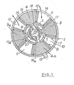
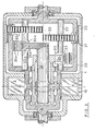
- FIGS. 1 and 2 a rotary volumetric motor is shown according to the invention which comprises a fixed external casing 1 limiting an annular space, on the one hand peripherally, on the other hand on its front and rear faces.
- the housing is shown in a single element in the drawings, for the purpose of simplification, but, of course, it includes the number of elements necessary to allow mounting.
- a rotary crown 2 which internally delimits this annular space in which move in rotation in the direction of the arrow F four pistons 3, 3a and 4, 4a.
- the pistons 3, 3a are symmetrical and connected by means of an arm 5 and the pistons 4, 4a are also symmetrical and connected in the same way by an arm 6.
- the arms 5 and 6 are respectively made integral with the shafts 27 and 28 by a key (not shown) or any other known means ...
- the annular space, in which the pistons move may have a quadrangular cross section as shown in Figure 2, or circular, for example in the simplest cases, or any combination of circular sectors and line segments in particular.
- the radial faces 7, 8 of the adjacent pistons delimit between them spaces 9, 10, 11, 12 of variable volume which correspond to the chambers of an engine operating according to a four-stroke cycle.
- the assembly constituted by the crown 2 and the pistons 3, 3a and 4, 4a is driven according to the same general rotary movement according to the arrow F, while the pistons 3, 3a and 4, 4a are further animated, as will be explained below, of a cyclic speed variation corresponding to a movement of acceleration and deceleration of each arm 5, 6 which causes an approximation and an alternative distancing of the pistons 3, 3a and 4, 4a in order to obtain a variation in cyclic volume of the spaces or chambers 9, 10, 11, 12 enabling a four-stroke cycle to be carried out.
- the chamber 9 is in the intake phase
- the chamber 10 in the compression phase the chamber 11 in the expansion phase
- the chamber 12 in the exhaust phase In the position shown in Figure 1, the chamber 9 is in the intake phase, the chamber 10 in the compression phase, the chamber 11 in the expansion phase and the chamber 12 in the exhaust phase.
- the ignition of the fuel mixture occurs when one of the chambers, in particular the chamber 10, is opposite the spark plug 13 which is mounted on the casing 1. Note that, in the case where the engine would operate according to a Diesel cycle, the spark plug 13 is replaced by a fuel injector.
- the casing 1 also has a light 14 for the admission of the combustible gas mixture in the case of an ignition engine or fresh air in the case of a diesel cycle and a light 15 for the exhaust of the gases. burned.
- the rotor ring 2 In order to allow the angular movement of the arms 5 and 6 for bringing the pistons closer and further apart, the rotor ring 2 includes slots 16, 16a and 17, 17a.
- Figure 1 shows a single seal at each end of the pistons but well heard there may be several in series.
- the joint plane between the fixed part 1 and the rotary crown 2 is located at the mean diameter of the torus.
- the outer casing may have three faces and sealing segments are placed in the connection zone of the inner rotary ring 2.
- the angular displacement of the pistons and their developed length are determined by the choice of the volumetric compression ratio to be achieved. We deduce the necessary dimension of the lights 16, 16a, 17, 17a in the crown 2 for the displacement of the pistons.
- the intake and exhaust ports can advantageously have the developed length corresponding to the maximum spacing of the pistons and the maximum width compatible with the fixed casing.
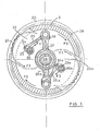
- the mechanical power produced at the level of the pistons is recovered on a shaft linked to the crown 2, by a "squirrel cage" 29, by means of a transmission device which comprises a fixed outer crown 20 (see FIGS. 2 and 3 ) having an internal toothing 21 with which mesh two pinions 22, 22a having a number of teeth equal to half that of the crown 20; These pinions 22, 22a are located in different planes and they do not mesh with each other.
- crank pin 30, 30a an eccentric axis 24, 24a on which is articulated at one end of a connecting rod 25, 25a, the other end of which is articulated on another crank pin 26, 26a.
- the crank pins 26, 26a are respectively integral with the shafts 27, 28 which carry the arms 5 and 6 driven by the pistons 3, 3a and 4, 4a.
- each pinion 22, 22a is driven by the corresponding connecting rod 25, 25a in the direction of the arrow F1.
- the axes of the pinions being integral with the crown 2, and due to the engagement of the pinions 22, 22a on the fixed outer crown 20, the crown 2 rotates along the arrow F2 (therefore in the opposite direction of rotation, pinions 22 and 22a on themselves), as well as the output shaft to which the motor force is applied.
- the articulated system of the three-bar type constituted by the crank pins 30, 30a, the connecting rods 25, 25a and the crank pins 26, 26a is dimensioned so that the complete rotation of the crank pins 30, 30a around their axis 23, 23a causes an alternating oscillation movement of the crank pins 26, 26a and therefore of the pistons between two extreme positions determined by the volumetric compression ratio chosen.
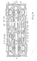
- Figure 6 is a longitudinal sectional view of the motor consisting of two modules arranged in the same casing 1, along the same axis, but angularly offset by 90 °, taking as reference the angle of rotation of the pinions.
- Each module is identical to that described above which is shown on the left with the same references while the right module which has been added has the same references but increased by a hundred.
- Each module comprises two pairs of pistons (of which only one piston is shown) 3, 4 and 103, 104 connected radially in pairs by means of two arms 5, 6 and 105, 106 and moving in an annular space delimited by the casing 1 and a rotary crown 29 and 129 constituting the output drive shaft 2 and 102.
- the rotary crowns 29 and 129 are connected together to form a single assembly and they are connected by a transmission means to the four shafts 27, 28, 127 , 128 which are integral with the arms 5, 6, 105, 106 carrying the pistons.
- the transmission means comprises two pinions 22, 22a common to the two modules which mesh with a ring gear 20 provided in the casing 1, each pinion 22, 22a is wedged respectively on a shaft common to the two modules 23, 123a and 23a, 123.
- the pinions 22 and 22a, common to the two modules, are between two radial walls 29a and 129a, one belonging to the left module, the other to the right module and forming part of the common assembly 29-129.
- the shaft 23, 123a is connected by a connecting rod 25 to the crankpin 26 of the external shaft 27 and by a connecting rod 125a to the crankpin 126a of the internal shaft 128.
- the shaft 23a, 123 is connected by a connecting rod 25a to the crankpin 26a of the internal shaft 28 and by a connecting rod 125 to the crankpin 126 of the external shaft 127.
- crank pin 26a associated with the shaft 23d and the crankpin 126 associated with the shaft 123 which drive the pinion 22a are angularly offset by 90 °.
- crank pin 26 associated with the shaft 23 and the crank pin 126a associated with the shaft 123a which drive the pinion 22 are angularly offset by 90 °.
Landscapes
- Engineering & Computer Science (AREA)
- Mechanical Engineering (AREA)
- General Engineering & Computer Science (AREA)
- Output Control And Ontrol Of Special Type Engine (AREA)
- Cylinder Crankcases Of Internal Combustion Engines (AREA)
- Transmission Devices (AREA)
- Hydraulic Motors (AREA)
Applications Claiming Priority (2)
| Application Number | Priority Date | Filing Date | Title |
|---|---|---|---|
| FR8002539 | 1980-02-06 | ||
| FR8002539A FR2475126A1 (fr) | 1980-02-06 | 1980-02-06 | Perfectionnement aux moteurs volumetriques rotatifs |
Publications (3)
| Publication Number | Publication Date |
|---|---|
| EP0034958A2 true EP0034958A2 (de) | 1981-09-02 |
| EP0034958A3 EP0034958A3 (en) | 1981-09-16 |
| EP0034958B1 EP0034958B1 (de) | 1984-05-16 |
Family
ID=9238261
Family Applications (1)
| Application Number | Title | Priority Date | Filing Date |
|---|---|---|---|
| EP81400130A Expired EP0034958B1 (de) | 1980-02-06 | 1981-01-29 | Motor mit Drehkolben, die eine periodisch veränderliche Geschwindigkeit haben, und Antriebsmitteln |
Country Status (5)
| Country | Link |
|---|---|
| US (1) | US4419057A (de) |
| EP (1) | EP0034958B1 (de) |
| JP (1) | JPS56159503A (de) |
| DE (1) | DE3163548D1 (de) |
| FR (1) | FR2475126A1 (de) |
Cited By (8)
| Publication number | Priority date | Publication date | Assignee | Title |
|---|---|---|---|---|
| WO1991015659A1 (en) * | 1990-04-02 | 1991-10-17 | Jaguar Cars | A rotary engine |
| EP0530771A1 (de) * | 1991-09-04 | 1993-03-10 | Wilhelm Geissler | Drehkolben-Kraftmaschine |
| EP0554227A1 (de) * | 1992-01-30 | 1993-08-04 | Nicolò Doveri | Motor mit Drehkolben, die eine periodisch veränderliche Geschwindigkeit haben und Antriebsmittel |
| FR2693503A1 (fr) * | 1992-07-07 | 1994-01-14 | Bard Jean | Dispositif mécanique utilisé pour former un moteur ou une pompe ou un compresseur à piston rotatif. |
| FR2694336A1 (fr) * | 1992-07-29 | 1994-02-04 | Canova Sarls Etablissements | Dispositif de liaison cinématique pour pistons rotatifs et moteur comprenant un tel dispositif. |
| RU2135777C1 (ru) * | 1997-05-13 | 1999-08-27 | Вигриянов Михаил Степанович | Роторная машина |
| RU2137932C1 (ru) * | 1998-04-13 | 1999-09-20 | Тверской государственный технический университет | Роторный двигатель внутреннего сгорания |
| RU2140550C1 (ru) * | 1998-04-14 | 1999-10-27 | Журавкин Герман Иванович | Роторно-поршневой двигатель |
Families Citing this family (9)
| Publication number | Priority date | Publication date | Assignee | Title |
|---|---|---|---|---|
| US5069604A (en) * | 1989-06-01 | 1991-12-03 | Al Sabih Adel K | Radial piston rotary device and drive mechanism |
| DE102005020221A1 (de) * | 2005-04-30 | 2006-11-02 | Franz Riedl | Rotationskolbenmaschine zur Verwendung als Arbeitsmaschine, Kraftmaschine oder Verbrennungsmotor |
| ES2312243B1 (es) * | 2006-01-25 | 2009-12-29 | Jordi Amell Amell | Motor rotativo. |
| US8176892B2 (en) * | 2006-06-08 | 2012-05-15 | Reisser Heinz-Gustav A | Internal combustion engine |
| AT506123B1 (de) | 2007-11-30 | 2009-08-15 | Fritz Mondl | Brennkraftmaschine mit innerer verbrennung |
| UA87229C2 (ru) * | 2007-12-04 | 2009-06-25 | Евгений Федорович Драчко | Роторно-поршневая машина объемного расширения |
| RU2012116634A (ru) * | 2009-10-02 | 2013-11-10 | Хуго Хулио КОПЕЛОВИЧ | Система для создания компрессоров и роторного двигателя, имеющих динамически изменяемые рабочий объем и частоту сжатия |
| UA101699C2 (ru) * | 2011-06-03 | 2013-04-25 | Евгений Федорович Драчко | Гибридный двигатель внутреннего сгорания |
| RU169997U1 (ru) * | 2016-10-11 | 2017-04-11 | Александр Николаевич Черноштанов | Устройство связи лопастей роторно-лопастного двигателя |
Family Cites Families (10)
| Publication number | Priority date | Publication date | Assignee | Title |
|---|---|---|---|---|
| GB314134A (en) | 1928-03-27 | 1929-06-27 | Frank Rogers | Rotary motors |
| FR38996E (fr) * | 1930-03-25 | 1931-08-10 | Perfectionnements aux pompes et compresseurs | |
| US2349848A (en) * | 1942-12-08 | 1944-05-30 | Davids Robert Brewster | Relative motion rotative mechanism |
| FR980793A (fr) * | 1943-03-05 | 1951-05-17 | Perfectionnements aux pompes ou compresseurs | |
| FR941674A (fr) | 1945-06-22 | 1949-01-18 | Perfectionnements aux moteurs ou pompes rotatifs | |
| FR953008A (fr) * | 1947-08-28 | 1949-11-29 | Moteur rotatif à explosions à double effet | |
| GB947351A (en) * | 1960-10-19 | 1964-01-22 | Jeannine Marie Suzanne Larpent | Rotary pumps, compressors and engines |
| FR1488266A (fr) * | 1966-03-17 | 1967-07-13 | Machine volumétrique utilisable comme pompe, moteur ou moto-pompe | |
| US3807368A (en) * | 1972-07-21 | 1974-04-30 | R Johnson | Rotary piston machine |
| GB1552432A (en) | 1976-06-18 | 1979-09-12 | Sharples L | Rotary piston internal combustion engine |
-
1980
- 1980-02-06 FR FR8002539A patent/FR2475126A1/fr active Granted
-
1981
- 1981-01-29 EP EP81400130A patent/EP0034958B1/de not_active Expired
- 1981-01-29 DE DE8181400130T patent/DE3163548D1/de not_active Expired
- 1981-02-03 US US06/231,107 patent/US4419057A/en not_active Expired - Lifetime
- 1981-02-04 JP JP1554681A patent/JPS56159503A/ja active Granted
Cited By (8)
| Publication number | Priority date | Publication date | Assignee | Title |
|---|---|---|---|---|
| WO1991015659A1 (en) * | 1990-04-02 | 1991-10-17 | Jaguar Cars | A rotary engine |
| EP0530771A1 (de) * | 1991-09-04 | 1993-03-10 | Wilhelm Geissler | Drehkolben-Kraftmaschine |
| EP0554227A1 (de) * | 1992-01-30 | 1993-08-04 | Nicolò Doveri | Motor mit Drehkolben, die eine periodisch veränderliche Geschwindigkeit haben und Antriebsmittel |
| FR2693503A1 (fr) * | 1992-07-07 | 1994-01-14 | Bard Jean | Dispositif mécanique utilisé pour former un moteur ou une pompe ou un compresseur à piston rotatif. |
| FR2694336A1 (fr) * | 1992-07-29 | 1994-02-04 | Canova Sarls Etablissements | Dispositif de liaison cinématique pour pistons rotatifs et moteur comprenant un tel dispositif. |
| RU2135777C1 (ru) * | 1997-05-13 | 1999-08-27 | Вигриянов Михаил Степанович | Роторная машина |
| RU2137932C1 (ru) * | 1998-04-13 | 1999-09-20 | Тверской государственный технический университет | Роторный двигатель внутреннего сгорания |
| RU2140550C1 (ru) * | 1998-04-14 | 1999-10-27 | Журавкин Герман Иванович | Роторно-поршневой двигатель |
Also Published As
| Publication number | Publication date |
|---|---|
| JPS56159503A (en) | 1981-12-08 |
| EP0034958B1 (de) | 1984-05-16 |
| US4419057A (en) | 1983-12-06 |
| JPS6147966B2 (de) | 1986-10-22 |
| FR2475126B1 (de) | 1983-02-25 |
| EP0034958A3 (en) | 1981-09-16 |
| DE3163548D1 (en) | 1984-06-20 |
| FR2475126A1 (fr) | 1981-08-07 |
Similar Documents
| Publication | Publication Date | Title |
|---|---|---|
| EP0034958B1 (de) | Motor mit Drehkolben, die eine periodisch veränderliche Geschwindigkeit haben, und Antriebsmitteln | |
| EP0034085B1 (de) | Gaserzeuger mit positiver Verdrängung | |
| WO1989009144A1 (fr) | Groupe motopropulseur, notamment pour vehicule automobile et vehicule comportant un tel groupe | |
| FR2487427A1 (fr) | Moteur a combustion interne a deux vilebrequins accouples | |
| EP0577715A1 (de) | Rotationsmaschine mit ringfoermiger kammer | |
| FR2652391A1 (fr) | Pompes et moteurs a multirotors. | |
| EP0019557A1 (de) | Brennkraftmaschine mit Taumelscheibe, ohne Kurbelwelle und Pleuelstange | |
| BE892384A (fr) | Moteur rotatif a combustion interne | |
| FR2694336A1 (fr) | Dispositif de liaison cinématique pour pistons rotatifs et moteur comprenant un tel dispositif. | |
| FR2730274A1 (fr) | Moteur a pistons rotatifs et combustion externe | |
| EP0083892A2 (de) | Umlaufmaschine mit Kolben, die eine ungleichförmige Umfangsgeschwindigkeit besitzen | |
| FR2716493A1 (fr) | Machine à pistons rotatifs utilisable notamment en tant que moteur thermique. | |
| FR2519697A1 (fr) | Machine a pistons | |
| FR2898383A1 (fr) | Ensemble mecanique pour la realisation de machines telles que compresseurs, moteurs thermiques ou autres, dotees d'un cylindre et d'un piston | |
| FR2474586A1 (fr) | Moteur a combustion interne, a disque, sans vilebrequin et sans bielle | |
| FR2988776A1 (fr) | Moteur rotatif a combustion interne et a taux de compression variable | |
| FR2544385A1 (fr) | Capsulisme rotatif a piston cylindrique diametral adaptable en pompe, compresseur ou moteur | |
| BE370233A (de) | ||
| FR2613770A1 (fr) | Moteur a combustion interne a deux temps | |
| EP3004550A1 (de) | Vorrichtung zum umwandeln einer bewegung und entsprechendes verfahren | |
| BE721913A (de) | ||
| FR2667650A1 (fr) | Moteur a combustion a pistons rotatifs. | |
| BE861936A (fr) | Moteur a pistons | |
| EP0391866A1 (de) | Fluidummaschine mit rotierender Bewegung | |
| FR2498250A2 (fr) | Generateur de gaz a variation de volume |
Legal Events
| Date | Code | Title | Description |
|---|---|---|---|
| PUAI | Public reference made under article 153(3) epc to a published international application that has entered the european phase |
Free format text: ORIGINAL CODE: 0009012 |
|
| PUAL | Search report despatched |
Free format text: ORIGINAL CODE: 0009013 |
|
| 17P | Request for examination filed |
Effective date: 19810205 |
|
| AK | Designated contracting states |
Designated state(s): DE FR GB |
|
| AK | Designated contracting states |
Designated state(s): DE FR GB |
|
| GRAA | (expected) grant |
Free format text: ORIGINAL CODE: 0009210 |
|
| AK | Designated contracting states |
Designated state(s): DE FR GB |
|
| REF | Corresponds to: |
Ref document number: 3163548 Country of ref document: DE Date of ref document: 19840620 |
|
| PLBE | No opposition filed within time limit |
Free format text: ORIGINAL CODE: 0009261 |
|
| STAA | Information on the status of an ep patent application or granted ep patent |
Free format text: STATUS: NO OPPOSITION FILED WITHIN TIME LIMIT |
|
| 26N | No opposition filed | ||
| PGFP | Annual fee paid to national office [announced via postgrant information from national office to epo] |
Ref country code: FR Payment date: 19981214 Year of fee payment: 19 |
|
| PGFP | Annual fee paid to national office [announced via postgrant information from national office to epo] |
Ref country code: GB Payment date: 19990128 Year of fee payment: 19 |
|
| PGFP | Annual fee paid to national office [announced via postgrant information from national office to epo] |
Ref country code: DE Payment date: 19990330 Year of fee payment: 19 |
|
| PG25 | Lapsed in a contracting state [announced via postgrant information from national office to epo] |
Ref country code: GB Free format text: LAPSE BECAUSE OF NON-PAYMENT OF DUE FEES Effective date: 20000129 |
|
| GBPC | Gb: european patent ceased through non-payment of renewal fee |
Effective date: 20000129 |
|
| PG25 | Lapsed in a contracting state [announced via postgrant information from national office to epo] |
Ref country code: FR Free format text: LAPSE BECAUSE OF NON-PAYMENT OF DUE FEES Effective date: 20000929 |
|
| PG25 | Lapsed in a contracting state [announced via postgrant information from national office to epo] |
Ref country code: DE Free format text: LAPSE BECAUSE OF NON-PAYMENT OF DUE FEES Effective date: 20001101 |
|
| REG | Reference to a national code |
Ref country code: FR Ref legal event code: ST |