EP0035006B1 - Method and apparatus for separating fibrillated mineral material out of a partly fibrillated mineral bloom - Google Patents
Method and apparatus for separating fibrillated mineral material out of a partly fibrillated mineral bloom Download PDFInfo
- Publication number
- EP0035006B1 EP0035006B1 EP81850022A EP81850022A EP0035006B1 EP 0035006 B1 EP0035006 B1 EP 0035006B1 EP 81850022 A EP81850022 A EP 81850022A EP 81850022 A EP81850022 A EP 81850022A EP 0035006 B1 EP0035006 B1 EP 0035006B1
- Authority
- EP
- European Patent Office
- Prior art keywords
- jets
- mineral
- fibrillating
- wheels
- fibrillated
- Prior art date
- Legal status (The legal status is an assumption and is not a legal conclusion. Google has not performed a legal analysis and makes no representation as to the accuracy of the status listed.)
- Expired
Links
- 229910052500 inorganic mineral Inorganic materials 0.000 title claims abstract description 37
- 239000011707 mineral Substances 0.000 title claims abstract description 37
- 238000000034 method Methods 0.000 title claims abstract description 21
- 239000000463 material Substances 0.000 title claims description 23
- XLYOFNOQVPJJNP-UHFFFAOYSA-N water Substances O XLYOFNOQVPJJNP-UHFFFAOYSA-N 0.000 claims abstract description 21
- 239000007788 liquid Substances 0.000 claims abstract description 14
- 239000012530 fluid Substances 0.000 claims description 6
- 239000000080 wetting agent Substances 0.000 claims description 4
- 230000001154 acute effect Effects 0.000 claims description 2
- 239000011049 pearl Substances 0.000 abstract description 18
- 239000002245 particle Substances 0.000 abstract description 4
- 239000000835 fiber Substances 0.000 description 14
- 238000000926 separation method Methods 0.000 description 11
- 238000005192 partition Methods 0.000 description 9
- 239000008188 pellet Substances 0.000 description 6
- 238000007664 blowing Methods 0.000 description 3
- 239000011490 mineral wool Substances 0.000 description 3
- 230000015572 biosynthetic process Effects 0.000 description 2
- 210000002268 wool Anatomy 0.000 description 2
- 230000007423 decrease Effects 0.000 description 1
- 239000006185 dispersion Substances 0.000 description 1
- 238000004519 manufacturing process Methods 0.000 description 1
- JTJMJGYZQZDUJJ-UHFFFAOYSA-N phencyclidine Chemical class C1CCCCN1C1(C=2C=CC=CC=2)CCCCC1 JTJMJGYZQZDUJJ-UHFFFAOYSA-N 0.000 description 1
- 230000002787 reinforcement Effects 0.000 description 1
- 230000003014 reinforcing effect Effects 0.000 description 1
Images

Classifications
-
- C—CHEMISTRY; METALLURGY
- C03—GLASS; MINERAL OR SLAG WOOL
- C03B—MANUFACTURE, SHAPING, OR SUPPLEMENTARY PROCESSES
- C03B37/00—Manufacture or treatment of flakes, fibres, or filaments from softened glass, minerals, or slags
- C03B37/01—Manufacture of glass fibres or filaments
- C03B37/04—Manufacture of glass fibres or filaments by using centrifugal force, e.g. spinning through radial orifices; Construction of the spinner cups therefor
- C03B37/05—Manufacture of glass fibres or filaments by using centrifugal force, e.g. spinning through radial orifices; Construction of the spinner cups therefor by projecting molten glass on a rotating body having no radial orifices
- C03B37/055—Manufacture of glass fibres or filaments by using centrifugal force, e.g. spinning through radial orifices; Construction of the spinner cups therefor by projecting molten glass on a rotating body having no radial orifices by projecting onto and spinning off the outer surface of the rotating body
Definitions
- Mineral fibres can be manufactured in many different ways from blooms of mineral materials. Basically there are three main methods:
- the drawing operation gives a fibre mass substantially without any portion of unfibrated material. With some reserve this can also be said concerning the blowing operation in which the fibre formation is made by means of hot gas flows.
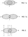
- figure 1 a shows a little successful separation in that the pearls represented by the area A are incompletely separated from the fibres which are represented by the area B.
- the area C which is common for the two areas A and B represent the part of the partially fibrated flow of material in which pearls and fibres appear mixed up.
- figure 1b shows a more successful separation in which the common field C provides a much less part of the total flow of material.
- the partition may also be moved so that one of the fractions is more clean than the other. This is illustrated in figure 2. Also in this figure the area A represents the pearls and the area B represents the fibres. If the flow of material is now parted as indicated with line a-a two portions are obtained, one containing more pearls than fibres and the other of the opposite character. If it were possible to provide a partition as shown by line b-b one part flow should comprise only pearls whereas the other part flow should comprise both fibres and some pearls. Another possible partition of interest is represented by line c-c which divides a fibre portion which is completely free from pearls.
- the partition between the two phases thereby generally is made somewhere between the lines a-a and b-b.
- the line b-b like the line c-c represent hypothetic partitions which cannot be reached in practice in the present manufacturing processes which are very stochastic to their nature.
- the said fraction which consequently contains a large amount of pearls, is thereafter moved to another station in which the material is dispersed in a water bath preferably by means of a wetting agent as dispersing means.
- the fibre mat supplied to the water bath often is present in wool form having a pellet like structure.
- any pellets are broken up into separate fibres.
- the dispersion thereby obtained may thereafter be subjected to more exactly operating separation steps, for instance by means of some type of wet cyclones. Not until after this step a pure fibre mass has been obtained.
- the fibre mass thus obtained does not contain all fibres which have been manufactured.
- the lost fibres are present among the main portion of the pearls and provides a little- portion thereof. It may be possible to separate also the said fibres from the pearls in a special separation step, but the fibres have already been subjected to such thermic and mechanical stresses that they have lost a substantial part of their good properties. Further such special separation step should involve additional actuation and destroying of the fibres.
- the invention consequently relates to a method and an apparatus for separating fibrillated mineral material out of a partially fibrillated mineral bloom which is ejected from rotating fibrating wheels to which a mineral bloom is supplied.
- jets or flows of a liquid medium especially water is used for deflecting the fibres thereby formed.
- An apparatus for carrying out the method of the invention is characterised in that the water flows are formed by nozzles having an elongated outflow opening, thus obtaining the aforesaid flat jets that provide a part of a cylindric or conical surface that covers a continuous length of the circumference of the fibrillating wheel or wheels.
- the flat jet may in turn be formed in several separate jets the edges of which get together before they meet the material ejected from the fibrating apparatus, especially the fibrating wheels.
- the latter embodiment of the jets is more easy to handle since it gives great possibilities to vary the flow and the speed at different places, since the amount of material ejected from the fibrating wheel is different for different parts of the wheel. The amount is largest adjacent the place where the mineral bloom is supplied and it successively decreases round the peripheries.
- An embodiment of the invention which has still greater possibilities of being adapted and optimized is the one in which several flat jets are provided on different levels over each other and in different areas so as to provide a covering and overlapping pattern as seen in the direction in which the material is thrown out from the surface of the fibrating wheel. If the overlapping of the jets is sufficiently large a relationship is obtained giving a great safety that any particle thrown out from the fibrating wheel is actuated by the jet or jets even if there should be any interruption in the supply of water to the separate nozzles from which the water jets emanate.
- the jets ought to be substantially parallel to the axes of the fibrating wheel but they may form an acute angle thereto, preferably so that the jets converge towards each other.
- the water jet is provided in connection to the outer periphery of the wheel combination in the same way as in the previously known apparatus using air or gas flows.
- FIGS. 1 a, 1 and 2 are diagrammatical representations of different degrees of separation of pearls and fibres respectively of a partly fibrated mineral bloom.
- Figure 3 diagrammatically shows an apparatus for executing the method according to the invention.
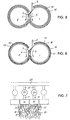
- Figure 4 is an axial side view of a part of the apparatus according to figure 3, and figure 5 and 6 show the apparatus according to figure 3 in a vertical transversal plane.
- Figure 7 shows the apparatus according to figure 6 in an axially spread outplane.
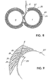
- FIGS 8 and 9 show two further embodiments of the apparatus according to figure 3.
- FIG 3 a fibrating apparatus comprising two wheels 1, 2, so called spin wheels, for fibration of a mineral bloom.
- the wheels rotate in the directions indicated with the arrows 3 and 4 respectively.
- From a flute the mineral bloom 6 flows downwards to meet the wheel 1.
- From wheel 1 a part from the mineral bloom is transferred to the fibrating wheel 2 by force action whereas another part of the bloom remains on the wheel first meeting the bloom.
- the centrifugal force the mineral bloom is thrown out from the two wheels in the tangential direction, whereby a large number of fibres are formed.
- a jet 8 substantially consisting of water is directed.
- the jet 8 comes from an opening 9 of a nozzle 10 which in turn is fed over a conduit 11. At the place where the jet hits the fibre 7 this is brought by the jet and is deflected from its previous path of movement as marked with the line 7' of figure 4.
- the nozzle 10 illustrated in the drawing cannot deflect more than a portion of the fibres which are thrown out from the wheel 2. It is necessary to use a substantially wider nozzle or to use several nozzles as shown in the following drawings.
- Figure 5 shows the two fibrating wheels 1 and 2 which are arranged side by side.
- the first wheel 1 is hit by the jet of mineral bloom 6 which falls vertically to the pattern surface of the wheel.
- the combined wheels are surrounded by a diffusor 14 in which there is a slot 15 which substantially completely encloses the wheel combination.
- FIG 6 is shown a similar arrangement in which the nozzle or the diffusor 14 as shown in figure 5 corresponds to a series of nozzles 16 in which there are a corresponding number of openings 17. If the outflow does not follow through a continuous opening like the one in figure 5 but through several different openings they should be provided as shown in figure 6.
- a number of distributed nozzles 16 each having an opening 17 are placed side by side.
- two of the said nozzles 16 whereas the adjacent two nozzles are marked with dotted lines.
- the nozzles 16 are provided so that the flat jet from each nozzle diverge in the plane whereby two adjacent jets 18 meet at a point 19 in front of the point where the fibres reach the flow of fluid.
- Figure 7 also shows how the nozzles are fed by conduits 11 including control valves 20.
- the flow medium is supplied to the control valves 20 from a supply conduit 22 over branch conduits 21.
- each jet 18 can be adjusted so that the dynamic force thereof meets the request at the very part of the wheel periphery where the nozzle in question is placed. It is obvious that different parts of the wheel periphery throw out different large amounts of melted mineral depending on the actual distance to the place where the jet of mineral wool 6 is supplied.
- Figure 8 shows an arrangement in which there is an inner set of nozzles 23 having openings 24 and in addition thereto an outer set of nozzles 25 having openings 26 provided round the fibrating wheels 1 and 2 which are fed with the jet of mineral bloom 6.
- the openings 26 are provided so as to cover the space between the jets coming from the openings 24.
- FIG 9 is shown an arrangement in which the fibrating wheel 27 to which the mineral wool is supplied rotates in the direction of the arrow 28.
- the wheel 27 is surrounded by a series of nozzles 29 having openings 30 arranged as tangents of the wheel 27 but in a direction which is opposite to the direction in which a particle is thrown out from the surface of the wheel.
- the openings 30 are wider at the part located closest to the wheel and they successively becomes narrower in the direction opposite to the wheel.
- the openings 30 are superposed on each other in such a way that all tangents 31 pass at least two openings.
Landscapes
- Engineering & Computer Science (AREA)
- Chemical & Material Sciences (AREA)
- General Life Sciences & Earth Sciences (AREA)
- Geochemistry & Mineralogy (AREA)
- Manufacturing & Machinery (AREA)
- Materials Engineering (AREA)
- Organic Chemistry (AREA)
- Life Sciences & Earth Sciences (AREA)
- Solid-Sorbent Or Filter-Aiding Compositions (AREA)
- Drilling And Exploitation, And Mining Machines And Methods (AREA)
- Spinning Methods And Devices For Manufacturing Artificial Fibers (AREA)
- Separation Of Solids By Using Liquids Or Pneumatic Power (AREA)
- Housing For Livestock And Birds (AREA)
- Inorganic Fibers (AREA)
- Agricultural Chemicals And Associated Chemicals (AREA)
- Saccharide Compounds (AREA)
- Paper (AREA)
- Nonwoven Fabrics (AREA)
Priority Applications (1)
| Application Number | Priority Date | Filing Date | Title |
|---|---|---|---|
| AT81850022T ATE4888T1 (de) | 1980-02-22 | 1981-02-12 | Verfahren und vorrichtung zum trennen von mineralfasern aus einer teilweise gefaserten mineralienschicht. |
Applications Claiming Priority (2)
| Application Number | Priority Date | Filing Date | Title |
|---|---|---|---|
| SE8001395A SE422321C (sv) | 1980-02-22 | 1980-02-22 | Forfarande och anordning for uppfangning av partiellt fibrerad mineral, som utslungas fran roterande fibreringshjul vilka pafors en mineralsmelta |
| SE8001395 | 1980-02-22 |
Publications (2)
| Publication Number | Publication Date |
|---|---|
| EP0035006A1 EP0035006A1 (en) | 1981-09-02 |
| EP0035006B1 true EP0035006B1 (en) | 1983-10-05 |
Family
ID=20340325
Family Applications (1)
| Application Number | Title | Priority Date | Filing Date |
|---|---|---|---|
| EP81850022A Expired EP0035006B1 (en) | 1980-02-22 | 1981-02-12 | Method and apparatus for separating fibrillated mineral material out of a partly fibrillated mineral bloom |
Country Status (11)
| Country | Link |
|---|---|
| US (1) | US4356017A (da) |
| EP (1) | EP0035006B1 (da) |
| JP (1) | JPS56129629A (da) |
| AT (1) | ATE4888T1 (da) |
| AU (1) | AU541817B2 (da) |
| CA (1) | CA1164662A (da) |
| DE (1) | DE3161069D1 (da) |
| DK (1) | DK156896C (da) |
| FI (1) | FI70876C (da) |
| NO (1) | NO148261C (da) |
| SE (1) | SE422321C (da) |
Families Citing this family (3)
| Publication number | Priority date | Publication date | Assignee | Title |
|---|---|---|---|---|
| US4594086A (en) * | 1984-02-27 | 1986-06-10 | Isover Saint-Gobain | Method and apparatus for distribution of fibres in a felt |
| SE443133C (sv) * | 1984-07-03 | 1987-11-16 | Rockwool Ab | Forfarande och anordning vid fibrering av mineralsmelta |
| FI121784B (sv) * | 2004-12-31 | 2011-04-15 | Paroc Oy Ab | Arrangemang och förfarande vid framställning av mineralull samt fibreringsanordning |
Citations (1)
| Publication number | Priority date | Publication date | Assignee | Title |
|---|---|---|---|---|
| US3159475A (en) * | 1955-05-05 | 1964-12-01 | Johns Manville | Apparatus for forming fibers |
Family Cites Families (3)
| Publication number | Priority date | Publication date | Assignee | Title |
|---|---|---|---|---|
| AT277851B (de) * | 1968-01-23 | 1970-01-12 | Voest Ag | Vorrichtung zum Herstellen von mineralischen Fasern, insbesondere Schlackenwolle |
| DE1796143B2 (de) * | 1968-09-07 | 1976-11-04 | Glaswerk Schuller Gmbh, 6980 Wertheim | Verfahren und vorrichtung zum einordnen von durch tropfenfall erzeugten faeden aus glas in eine oder mehrere aus einer vielzahl derselben bestehenden fadenebenen |
| US4252550A (en) * | 1979-05-01 | 1981-02-24 | Glaswerk Schuller Gmbh | Method and apparatus for the integration of newly formed filaments into a continuous strand |
-
1980
- 1980-02-22 SE SE8001395A patent/SE422321C/sv not_active IP Right Cessation
-
1981
- 1981-02-12 EP EP81850022A patent/EP0035006B1/en not_active Expired
- 1981-02-12 AT AT81850022T patent/ATE4888T1/de not_active IP Right Cessation
- 1981-02-12 DE DE8181850022T patent/DE3161069D1/de not_active Expired
- 1981-02-17 JP JP2097381A patent/JPS56129629A/ja active Granted
- 1981-02-18 US US06/235,606 patent/US4356017A/en not_active Expired - Lifetime
- 1981-02-20 AU AU67510/81A patent/AU541817B2/en not_active Ceased
- 1981-02-20 FI FI810521A patent/FI70876C/fi not_active IP Right Cessation
- 1981-02-20 DK DK079481A patent/DK156896C/da not_active IP Right Cessation
- 1981-02-20 NO NO810602A patent/NO148261C/no unknown
- 1981-02-20 CA CA000371333A patent/CA1164662A/en not_active Expired
Patent Citations (1)
| Publication number | Priority date | Publication date | Assignee | Title |
|---|---|---|---|---|
| US3159475A (en) * | 1955-05-05 | 1964-12-01 | Johns Manville | Apparatus for forming fibers |
Also Published As
| Publication number | Publication date |
|---|---|
| DK156896B (da) | 1989-10-16 |
| AU6751081A (en) | 1981-08-27 |
| DK79481A (da) | 1981-08-23 |
| ATE4888T1 (de) | 1983-10-15 |
| JPH0159219B2 (da) | 1989-12-15 |
| SE422321B (sv) | 1982-03-01 |
| US4356017A (en) | 1982-10-26 |
| DK156896C (da) | 1990-02-26 |
| NO810602L (no) | 1981-08-24 |
| JPS56129629A (en) | 1981-10-09 |
| DE3161069D1 (en) | 1983-11-10 |
| EP0035006A1 (en) | 1981-09-02 |
| FI810521L (fi) | 1981-08-23 |
| SE8001395L (sv) | 1981-08-23 |
| NO148261C (no) | 1983-09-07 |
| AU541817B2 (en) | 1985-01-24 |
| FI70876B (fi) | 1986-07-18 |
| NO148261B (no) | 1983-05-30 |
| CA1164662A (en) | 1984-04-03 |
| SE422321C (sv) | 1984-01-23 |
| FI70876C (fi) | 1986-10-27 |
Similar Documents
| Publication | Publication Date | Title |
|---|---|---|
| US5232638A (en) | Apparatus and method for introducing additives to fibrous products | |
| CA2092318C (en) | Process and apparatus for making mineral wool fibres | |
| HRP940811A2 (en) | Process and apparatus for fiberising of mineral wool by means of free centrifugation | |
| JPS5876562A (ja) | ガス流によつて運ばれる繊維の受入れ素子における分配を改良するための方法および装置 | |
| EP0878450B1 (en) | Scrap fiber refeed system and method | |
| PL133238B1 (en) | Method of obtaining mineral fibres and apparatus therefor | |
| EP0035006B1 (en) | Method and apparatus for separating fibrillated mineral material out of a partly fibrillated mineral bloom | |
| CA1262631A (en) | Method and apparatus for fibrating molten mineral material | |
| US5116397A (en) | Fibrillation device for the manufacture of mineral wool | |
| US5961897A (en) | Manufacture of man-made vitreous fiber products | |
| US3060674A (en) | Method for producing glass roving | |
| WO1987007887A1 (en) | An apparatus for the defibration of molten mineral material | |
| WO1997003027A1 (en) | Centrifuging process for forming fibers | |
| AU718485B2 (en) | Process and device for the free centrifuging of mineral fibres | |
| US3259939A (en) | Apparatus for forming and processing textile fibers and filamentary materials | |
| EP0883707A1 (en) | Webs of man-made vitreous fibres | |
| RU2367626C2 (ru) | Устройство и способ изготовления минеральной шерсти и волокнообразующая установка | |
| JP2590331B2 (ja) | 直状繊維の製造方法 | |
| EP2165984A1 (de) | Zerfaserungsvorrichtung zur Herstellung von Glaswolle | |
| SU876566A1 (ru) | Устройство дл получени волокон из силикатного расплава | |
| PL182906B1 (pl) | Urządzenie do wytwarzania wyrobów ze sztucznych włókien szklistych i sposób wytwarzania wyrobów ze sztucznych włókien szklistych | |
| NO880596L (no) | Apparat for defibrering av smeltet mineralmateriale. | |
| HRP970032A2 (en) | Process and device for the free centrifuging of mineral fibres |
Legal Events
| Date | Code | Title | Description |
|---|---|---|---|
| PUAI | Public reference made under article 153(3) epc to a published international application that has entered the european phase |
Free format text: ORIGINAL CODE: 0009012 |
|
| AK | Designated contracting states |
Designated state(s): AT BE CH DE FR GB IT LU NL |
|
| 17P | Request for examination filed |
Effective date: 19810904 |
|
| ITF | It: translation for a ep patent filed | ||
| GRAA | (expected) grant |
Free format text: ORIGINAL CODE: 0009210 |
|
| AK | Designated contracting states |
Designated state(s): AT BE CH DE FR GB IT LI LU NL |
|
| REF | Corresponds to: |
Ref document number: 4888 Country of ref document: AT Date of ref document: 19831015 Kind code of ref document: T |
|
| REF | Corresponds to: |
Ref document number: 3161069 Country of ref document: DE Date of ref document: 19831110 |
|
| ET | Fr: translation filed | ||
| PLBE | No opposition filed within time limit |
Free format text: ORIGINAL CODE: 0009261 |
|
| STAA | Information on the status of an ep patent application or granted ep patent |
Free format text: STATUS: NO OPPOSITION FILED WITHIN TIME LIMIT |
|
| 26N | No opposition filed | ||
| REG | Reference to a national code |
Ref country code: FR Ref legal event code: TP |
|
| NLS | Nl: assignments of ep-patents |
Owner name: LAXA BRUK AB TE LAXA, ZWEDEN. |
|
| ITPR | It: changes in ownership of a european patent |
Owner name: CESSIONE;LAXA BRUK A.B. |
|
| ITTA | It: last paid annual fee | ||
| PGFP | Annual fee paid to national office [announced via postgrant information from national office to epo] |
Ref country code: GB Payment date: 19920211 Year of fee payment: 12 |
|
| PGFP | Annual fee paid to national office [announced via postgrant information from national office to epo] |
Ref country code: LU Payment date: 19920212 Year of fee payment: 12 |
|
| PGFP | Annual fee paid to national office [announced via postgrant information from national office to epo] |
Ref country code: FR Payment date: 19920226 Year of fee payment: 12 |
|
| PGFP | Annual fee paid to national office [announced via postgrant information from national office to epo] |
Ref country code: AT Payment date: 19920228 Year of fee payment: 12 |
|
| PGFP | Annual fee paid to national office [announced via postgrant information from national office to epo] |
Ref country code: NL Payment date: 19920229 Year of fee payment: 12 |
|
| PGFP | Annual fee paid to national office [announced via postgrant information from national office to epo] |
Ref country code: BE Payment date: 19920303 Year of fee payment: 12 |
|
| PGFP | Annual fee paid to national office [announced via postgrant information from national office to epo] |
Ref country code: DE Payment date: 19920330 Year of fee payment: 12 |
|
| PGFP | Annual fee paid to national office [announced via postgrant information from national office to epo] |
Ref country code: CH Payment date: 19920429 Year of fee payment: 12 |
|
| EPTA | Lu: last paid annual fee | ||
| PG25 | Lapsed in a contracting state [announced via postgrant information from national office to epo] |
Ref country code: LU Free format text: LAPSE BECAUSE OF NON-PAYMENT OF DUE FEES Effective date: 19930212 Ref country code: GB Effective date: 19930212 Ref country code: AT Effective date: 19930212 |
|
| PG25 | Lapsed in a contracting state [announced via postgrant information from national office to epo] |
Ref country code: CH Effective date: 19930228 Ref country code: LI Effective date: 19930228 Ref country code: BE Effective date: 19930228 |
|
| BERE | Be: lapsed |
Owner name: LAXA BRUK A.B. Effective date: 19930228 |
|
| PG25 | Lapsed in a contracting state [announced via postgrant information from national office to epo] |
Ref country code: NL Effective date: 19930901 |
|
| GBPC | Gb: european patent ceased through non-payment of renewal fee |
Effective date: 19930212 |
|
| NLV4 | Nl: lapsed or anulled due to non-payment of the annual fee | ||
| PG25 | Lapsed in a contracting state [announced via postgrant information from national office to epo] |
Ref country code: FR Effective date: 19931029 |
|
| REG | Reference to a national code |
Ref country code: CH Ref legal event code: PL |
|
| PG25 | Lapsed in a contracting state [announced via postgrant information from national office to epo] |
Ref country code: DE Effective date: 19931103 |
|
| REG | Reference to a national code |
Ref country code: FR Ref legal event code: ST |