EP0035010B1 - Vorrichtung zur Herstellung profilierter, plattenförmiger Formlinge, vorzugsweise Dachziegel, aus Beton od.dgl. - Google Patents
Vorrichtung zur Herstellung profilierter, plattenförmiger Formlinge, vorzugsweise Dachziegel, aus Beton od.dgl. Download PDFInfo
- Publication number
- EP0035010B1 EP0035010B1 EP81890026A EP81890026A EP0035010B1 EP 0035010 B1 EP0035010 B1 EP 0035010B1 EP 81890026 A EP81890026 A EP 81890026A EP 81890026 A EP81890026 A EP 81890026A EP 0035010 B1 EP0035010 B1 EP 0035010B1
- Authority
- EP
- European Patent Office
- Prior art keywords
- manufacture
- hard metal
- smoothing device
- arcuate
- portions
- Prior art date
- Legal status (The legal status is an assumption and is not a legal conclusion. Google has not performed a legal analysis and makes no representation as to the accuracy of the status listed.)
- Expired
Links
- 238000004519 manufacturing process Methods 0.000 title claims description 16
- 229910052751 metal Inorganic materials 0.000 claims description 24
- 239000002184 metal Substances 0.000 claims description 24
- 238000009499 grossing Methods 0.000 claims description 18
- 239000000203 mixture Substances 0.000 claims description 6
- 229910000831 Steel Inorganic materials 0.000 claims description 5
- 239000010959 steel Substances 0.000 claims description 5
- 238000007493 shaping process Methods 0.000 claims description 2
- 239000011248 coating agent Substances 0.000 claims 6
- 238000000576 coating method Methods 0.000 claims 6
- 230000006835 compression Effects 0.000 claims 4
- 238000007906 compression Methods 0.000 claims 4
- 239000003082 abrasive agent Substances 0.000 claims 1
- 239000000463 material Substances 0.000 description 13
- 238000000465 moulding Methods 0.000 description 8
- 238000009415 formwork Methods 0.000 description 7
- 238000005056 compaction Methods 0.000 description 4
- XEEYBQQBJWHFJM-UHFFFAOYSA-N Iron Chemical group [Fe] XEEYBQQBJWHFJM-UHFFFAOYSA-N 0.000 description 3
- 239000004033 plastic Substances 0.000 description 3
- PXHVJJICTQNCMI-UHFFFAOYSA-N Nickel Chemical compound [Ni] PXHVJJICTQNCMI-UHFFFAOYSA-N 0.000 description 2
- 235000019589 hardness Nutrition 0.000 description 2
- 238000003860 storage Methods 0.000 description 2
- 238000003466 welding Methods 0.000 description 2
- 229910001208 Crucible steel Inorganic materials 0.000 description 1
- RTAQQCXQSZGOHL-UHFFFAOYSA-N Titanium Chemical compound [Ti] RTAQQCXQSZGOHL-UHFFFAOYSA-N 0.000 description 1
- 229910001315 Tool steel Inorganic materials 0.000 description 1
- 238000005299 abrasion Methods 0.000 description 1
- 239000000853 adhesive Substances 0.000 description 1
- 230000001070 adhesive effect Effects 0.000 description 1
- 229910045601 alloy Inorganic materials 0.000 description 1
- 239000000956 alloy Substances 0.000 description 1
- 238000005219 brazing Methods 0.000 description 1
- 239000010941 cobalt Substances 0.000 description 1
- 229910017052 cobalt Inorganic materials 0.000 description 1
- GUTLYIVDDKVIGB-UHFFFAOYSA-N cobalt atom Chemical compound [Co] GUTLYIVDDKVIGB-UHFFFAOYSA-N 0.000 description 1
- 238000010276 construction Methods 0.000 description 1
- 230000007812 deficiency Effects 0.000 description 1
- 239000003822 epoxy resin Substances 0.000 description 1
- 229910052742 iron Inorganic materials 0.000 description 1
- NFFIWVVINABMKP-UHFFFAOYSA-N methylidynetantalum Chemical compound [Ta]#C NFFIWVVINABMKP-UHFFFAOYSA-N 0.000 description 1
- 229910052759 nickel Inorganic materials 0.000 description 1
- 230000000149 penetrating effect Effects 0.000 description 1
- 229920000647 polyepoxide Polymers 0.000 description 1
- 238000005476 soldering Methods 0.000 description 1
- 229910003468 tantalcarbide Inorganic materials 0.000 description 1
- 239000010936 titanium Substances 0.000 description 1
- 229910052719 titanium Inorganic materials 0.000 description 1
- 210000002105 tongue Anatomy 0.000 description 1
- WFKWXMTUELFFGS-UHFFFAOYSA-N tungsten Chemical compound [W] WFKWXMTUELFFGS-UHFFFAOYSA-N 0.000 description 1
- 229910052721 tungsten Inorganic materials 0.000 description 1
- 239000010937 tungsten Substances 0.000 description 1
- UONOETXJSWQNOL-UHFFFAOYSA-N tungsten carbide Chemical compound [W+]#[C-] UONOETXJSWQNOL-UHFFFAOYSA-N 0.000 description 1
Images

Classifications
-
- B—PERFORMING OPERATIONS; TRANSPORTING
- B28—WORKING CEMENT, CLAY, OR STONE
- B28B—SHAPING CLAY OR OTHER CERAMIC COMPOSITIONS; SHAPING SLAG; SHAPING MIXTURES CONTAINING CEMENTITIOUS MATERIAL, e.g. PLASTER
- B28B3/00—Producing shaped articles from the material by using presses; Presses specially adapted therefor
- B28B3/12—Producing shaped articles from the material by using presses; Presses specially adapted therefor wherein one or more rollers exert pressure on the material
- B28B3/123—Producing shaped articles from the material by using presses; Presses specially adapted therefor wherein one or more rollers exert pressure on the material on material in moulds or on moulding surfaces moving continuously underneath or between the rollers, e.g. on an endless belt
-
- B—PERFORMING OPERATIONS; TRANSPORTING
- B28—WORKING CEMENT, CLAY, OR STONE
- B28B—SHAPING CLAY OR OTHER CERAMIC COMPOSITIONS; SHAPING SLAG; SHAPING MIXTURES CONTAINING CEMENTITIOUS MATERIAL, e.g. PLASTER
- B28B3/00—Producing shaped articles from the material by using presses; Presses specially adapted therefor
- B28B3/12—Producing shaped articles from the material by using presses; Presses specially adapted therefor wherein one or more rollers exert pressure on the material
Definitions
- the invention relates to a device for the production of profiled, plate-shaped moldings, preferably roof tiles, made of concrete or the like or the like. Filled formwork is carried out in the production direction and the moldings located therein are compacted and profiled, the compacting roller and / or the smoother having a surface made of hard metal in their surface areas subject to wear.
- One problem with the manufacture of such a device is to bring the hard material of the support into perfect conformity with the profile of the base, in order thereby to ensure that these parts are reliably connected by welding or the like. Ensure the necessary surface contact of the connecting surfaces.
- both its base and its support were divided into individual strips, each base strip being connected individually to a strip of the same width of the material forming the support. These strips made of different materials were then joined together to the full width of the smoothing and z. B. clamped together by bolts.
- the object of the present invention is to remedy these deficiencies and to design a device of the type described at the outset in such a way that the above-mentioned difficulties are avoided.
- the hard metal layer has an intermediate layer with a base, preferably made of steel, optionally with a positive fit, for example, as such, via an intermediate layer consisting of a metal-plastic mixture, preferably a steel-plastic mixture known - is connected by means of interlocking, undercut profiled tongues and grooves.
- the hard metal support of the compacting roller or of the smoothing machine can be divided according to its profile over its entire width and can be assembled from sections.
- This can advantageously be used for the production of roof tiles with a plurality of regions which extend over the entire width, in part domed and in part flat, in particular for the production of so-called Roman profiles.
- a design of the device components is to be developed in which a desirably simple, robust and hard-wearing form of the hard metal supports can be used.
- the hard metal support of the smoothing device - according to the profile of the roof tiles to be produced, which have partly curved and partly flat areas over their width - can be divided into as many flat and curved sections, which are joined together with their longitudinal edges and joined to the base.
- the base of the compaction roller can advantageously also be subdivided according to the profile of the roof tiles into those sections which are then mounted on a common drive shaft. This results in a further advantage that such sections can be replaced or renewed individually in the event of breakage, without the need to replace the entire component.
- separate sections of the base of the compacting roller are assigned to the curved areas, the flat areas and the area of the profiling of the roof tile provided with folds.
- the Compaction roller is a hard metal pad attached to the base by means of the intermediate layer.
- the sections of the arched areas can therefore consist entirely of a material that is softer than the hard metal of the supports, especially since the sections are compact and comparatively small and are not subject to any risk of breakage from the outset.
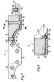
- Figures 1 to 3 first represent the storage container 1, in which the concrete to be processed with a grain size of the aggregate of about 0 to 3 mm is fed from a mixer and in which it from the rotating distributor, for. B. a spiked roller 2, the task of which is to distribute the material evenly, is promoted under the compressor roller 3, the so-called «roller». The underside of this compacting roller 3 is also fed formwork molds 5 for the moldings 6 to be molded on a machine bed 4 (FIG. 3).
- the formwork forms 5 filled with the compacted concrete get under the smoother 7, which is inclined at a certain angle of attack with respect to the machine bed 4 and with its end face, which is formed to a pointed edge and faces the compacting roller 3, connects tangentially directly to its underside.
- the smoother 7 is held by a bridge 9 spanning the machine bed 4 and the conveying path of the formwork forms 5.
- the direction of manufacture and the direction of conveyance of the formwork 5 is indicated by the arrow 10.
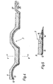
- the smoother 7 shown in FIGS. 4 and 5 on a larger scale in the longitudinal and cross-section now has a base 11 made of cast or forged steel, which has an initially castable, hardenable mixture of about 80% steel and 20% Epoxy resin existing intermediate layer 12 is connected to a support 13 consisting of the so-called hard metal.
- hard metal With hard metal is known a sintered metal hard alloy, which consists of one or more hard materials, eg. B. tungsten, titanium, tantalum carbide, etc. with a binding metal of the iron group, mostly cobalt but also nickel or iron, and has a particularly high hardness and wear resistance.
- hard materials eg. B. tungsten, titanium, tantalum carbide, etc.
- a binding metal of the iron group mostly cobalt but also nickel or iron, and has a particularly high hardness and wear resistance.
- connection between the base 11 and the support 13 essentially results from the cementing by means of the intermediate layer 12, but - according to the embodiment according to FIGS. 4 and 5 - undercut profiled springs 14 and grooves 15 can also additionally be provided for the positive locking of these Connection may be provided, as shown in Fig.5.
- the support consists of sections which correspond to the flat or curved areas of the smoothing device 7 and are connected to the base 11 with their longitudinal edges closely joined together.
- the pad 13 could - in the context of the invention - also consist of one piece.
- An edge part 27 of the smoothing device 7 is profiled with folds 26; it can consist entirely of hard metal.
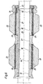
- the compressor roller 3 shows the construction according to the invention shown in FIG. 6, namely its base 16 consists of the sections 17, 17 ', 18 and 19 which are lined up on the drive shaft 20 and held in a rotationally fixed manner by means of a wedge 21 and a nut 22.
- This compacting roller 3 also includes - in accordance with the profiling of the moldings 6 to be produced - partly flat, partly curved, profiled areas, namely the sections 17 and 17 'are the less stressed curved areas, the two sections 18, however, the more stressed flat areas and the section 19 assigned to the edge region of the compressor roller 3 which forms the lateral folds of the roof tile molding 6.
- the small sections 17 and 17 ' because they are less stressed, can be made in one piece from a comparatively softer and easier to machine hard metal.
- Sections 18 and section 19 each carry a support 23 made of harder hard metal in order to be sufficiently wear-resistant.
- the supports 23 of the sections 18 and the support 24 of the section 19 are in turn connected to the base 16 or its sections via an intermediate layer 25 from the above-mentioned suitable metal-plastic mixture.
- the one-piece hard metal support 13 has depressions 28 on its side facing the base 11, into which threaded bushings 29 are soldered.
- the edge part 27 of the smoothing device, which is profiled with folds 26, also carries such threaded bushings 29.
- the hard metal support 13 is screwed into these threaded bushings 29 and penetrates the base 11, preferably by means of so-called Allen screws, which have an angular recess in the head for rotation. connected to the base 11.
- the smoothing device On its end facing away from the compacting roller, the smoothing device is connected by means of screws 32 to a strip 31 overlapping the edge of hard metal support 13.
- This bar 31 made of steel, takes over part of the strong thrust forces acting on the hard metal support 13 and thereby secures its connection to the base 11 of the smoothing device 7.
- the hard metal layer 13 of the smoothing device 7 in the edge area 13 '(FIG. 8) immediately adjoining the compacting roller 3 is made of a softer material than in the rest of the area which is more subject to abrasion, these two areas having different hardnesses in the Border zone 33 merge continuously.
- the intermediate layers 12 and 25 of the components of the device according to the invention serve, as already explained at the outset, to compensate for the various changes in shape of the different materials from which these components are composed, and in this way prevent the occurrence of dangerous internal stresses; at the same time, they ensure reliable binding of the supports 13, 23, 24 to the bases 11 and 16 of these components.
- the material of these intermediate layers 12 and 25 can be poured between the bases and the pads before hardening and then hardened.
- the durability of the shaping components of the device designed according to the invention optimally guarantees a uniform, consistently high quality and extensive dimensional and weight accuracy of the moldings.
Landscapes
- Engineering & Computer Science (AREA)
- Manufacturing & Machinery (AREA)
- Chemical & Material Sciences (AREA)
- Ceramic Engineering (AREA)
- Mechanical Engineering (AREA)
- Adornments (AREA)
- Forging (AREA)
- Laminated Bodies (AREA)
- Devices For Post-Treatments, Processing, Supply, Discharge, And Other Processes (AREA)
- Moulds, Cores, Or Mandrels (AREA)
- Press-Shaping Or Shaping Using Conveyers (AREA)
Priority Applications (1)
| Application Number | Priority Date | Filing Date | Title |
|---|---|---|---|
| AT81890026T ATE5303T1 (de) | 1981-02-16 | 1981-02-16 | Vorrichtung zur herstellung profilierter, plattenfoermiger formlinge, vorzugsweise dachziegel, aus beton od.dgl. |
Applications Claiming Priority (2)
| Application Number | Priority Date | Filing Date | Title |
|---|---|---|---|
| AT1050/80 | 1980-02-26 | ||
| AT0105080A AT368436B (de) | 1980-02-26 | 1980-02-26 | Vorrichtung zur herstellung profilierter dachziegel aus beton od.dgl. |
Publications (2)
| Publication Number | Publication Date |
|---|---|
| EP0035010A1 EP0035010A1 (de) | 1981-09-02 |
| EP0035010B1 true EP0035010B1 (de) | 1983-11-16 |
Family
ID=3505500
Family Applications (1)
| Application Number | Title | Priority Date | Filing Date |
|---|---|---|---|
| EP81890026A Expired EP0035010B1 (de) | 1980-02-26 | 1981-02-16 | Vorrichtung zur Herstellung profilierter, plattenförmiger Formlinge, vorzugsweise Dachziegel, aus Beton od.dgl. |
Country Status (7)
| Country | Link |
|---|---|
| EP (1) | EP0035010B1 (da) |
| AT (1) | AT368436B (da) |
| AU (1) | AU547961B2 (da) |
| DE (1) | DE3161392D1 (da) |
| DK (1) | DK152415C (da) |
| NZ (1) | NZ196325A (da) |
| ZA (1) | ZA811055B (da) |
Cited By (2)
| Publication number | Priority date | Publication date | Assignee | Title |
|---|---|---|---|---|
| CN106217597A (zh) * | 2016-09-07 | 2016-12-14 | 山东华平新材料科技有限公司 | 使无机非金属材料成型的设备和方法 |
| CN106217596A (zh) * | 2016-09-07 | 2016-12-14 | 山东华平新材料科技有限公司 | 使无机非金属材料成型的设备和方法 |
Families Citing this family (7)
| Publication number | Priority date | Publication date | Assignee | Title |
|---|---|---|---|---|
| IE53484B1 (en) * | 1981-02-13 | 1988-11-23 | Redland Roof Tiles Ltd | Wire electrode spark erosion |
| AU594656B2 (en) * | 1984-12-11 | 1990-03-15 | Thomas William Whitelaw | Tile making apparatus and method |
| DE3506726A1 (de) * | 1985-02-26 | 1986-08-28 | Reifenhäuser GmbH & Co Maschinenfabrik, 5210 Troisdorf | Verschleisswiderstandserhoehende beschichtung am zylinder und an der schnecke einer kunststoff-schneckenpresse |
| DE3506668A1 (de) * | 1985-02-26 | 1986-08-28 | Reifenhäuser GmbH & Co Maschinenfabrik, 5210 Troisdorf | Verschleisswiderstandserhoehende beschichtung am zylinder und an der schnecke einer kunststoff-schneckenpresse |
| DE3738361C1 (de) * | 1987-11-12 | 1989-01-26 | Werner Dipl-Ing Mandt | Profilmundstueck zur Herstellung von Betondachsteinen |
| GB2277707B (en) * | 1993-04-29 | 1996-07-03 | Redland Technology Ltd | Improvements in a roof tile making machine |
| CN103448143A (zh) * | 2013-08-15 | 2013-12-18 | 光明铁道控股有限公司 | 一种重载混凝土岔枕的生产方法 |
Citations (2)
| Publication number | Priority date | Publication date | Assignee | Title |
|---|---|---|---|---|
| GB739860A (en) * | 1953-03-30 | 1955-11-02 | Aodogan O Rahilly | Improvements in machines for moulding tiles and the like |
| DE1683517A1 (de) * | 1966-03-07 | 1969-11-06 | Schlosser & Co Gmbh | Form- und Bearbeitungswerkzeuge fuer die Betonindustrie |
Family Cites Families (3)
| Publication number | Priority date | Publication date | Assignee | Title |
|---|---|---|---|---|
| DE142084C (da) * | ||||
| GB739800A (en) * | 1954-10-19 | 1955-11-02 | Ciba Ltd | Aqueous pharmaceutical solutions of reserpine for parenteral administration |
| DE1584724C3 (de) * | 1965-05-04 | 1975-11-06 | Schaper Geb. Krueger, Gisela, 3251 Messenkamp | Vorrichtung zur Herstellung von Dachpfannen, insbesondere von Betondachpfannen |
-
1980
- 1980-02-26 AT AT0105080A patent/AT368436B/de not_active IP Right Cessation
-
1981
- 1981-02-16 EP EP81890026A patent/EP0035010B1/de not_active Expired
- 1981-02-16 DE DE8181890026T patent/DE3161392D1/de not_active Expired
- 1981-02-17 ZA ZA00811055A patent/ZA811055B/xx unknown
- 1981-02-18 DK DK070081A patent/DK152415C/da not_active IP Right Cessation
- 1981-02-19 AU AU67467/81A patent/AU547961B2/en not_active Ceased
- 1981-02-23 NZ NZ196325A patent/NZ196325A/en unknown
Patent Citations (2)
| Publication number | Priority date | Publication date | Assignee | Title |
|---|---|---|---|---|
| GB739860A (en) * | 1953-03-30 | 1955-11-02 | Aodogan O Rahilly | Improvements in machines for moulding tiles and the like |
| DE1683517A1 (de) * | 1966-03-07 | 1969-11-06 | Schlosser & Co Gmbh | Form- und Bearbeitungswerkzeuge fuer die Betonindustrie |
Cited By (2)
| Publication number | Priority date | Publication date | Assignee | Title |
|---|---|---|---|---|
| CN106217597A (zh) * | 2016-09-07 | 2016-12-14 | 山东华平新材料科技有限公司 | 使无机非金属材料成型的设备和方法 |
| CN106217596A (zh) * | 2016-09-07 | 2016-12-14 | 山东华平新材料科技有限公司 | 使无机非金属材料成型的设备和方法 |
Also Published As
| Publication number | Publication date |
|---|---|
| EP0035010A1 (de) | 1981-09-02 |
| DK70081A (da) | 1981-08-27 |
| ZA811055B (en) | 1982-09-29 |
| DK152415C (da) | 1988-08-01 |
| DE3161392D1 (en) | 1983-12-22 |
| NZ196325A (en) | 1984-05-31 |
| AU547961B2 (en) | 1985-11-14 |
| AT368436B (de) | 1982-10-11 |
| AU6746781A (en) | 1981-09-03 |
| ATA105080A (de) | 1982-02-15 |
| DK152415B (da) | 1988-02-29 |
Similar Documents
| Publication | Publication Date | Title |
|---|---|---|
| DE2930186C2 (de) | Förderbandtreibwalze | |
| DE69107746T2 (de) | Verfahren zur Herstellung eines bimetallischen Gussstückes und Verschleissteil nach diesem Verfahren. | |
| EP0443195A1 (de) | Verschleissfeste Oberflächenpanzerung für die Walzen von Walzenmaschinen, insbesondere von Hochdruck-Walzenpressen | |
| CH616869A5 (da) | ||
| EP2825316B1 (de) | Presswalze | |
| DE1482420A1 (de) | Schutzelemente fuer starker Abnutzung ausgesetzte Flaechen | |
| EP0332737A2 (de) | Vorrichtung zur Herstellung mehrschichtiger Betondachsteine | |
| EP0035010A1 (de) | Vorrichtung zur Herstellung profilierter, plattenförmiger Formlinge, vorzugsweise Dachziegel, aus Beton od.dgl. | |
| DE69401274T2 (de) | Verbesserungen für eine vorrichtung zum herstellen von dachziegeln | |
| DE2612210B1 (de) | Verbundkoerper und verfahren zu seiner herstellung | |
| DE3404030C1 (de) | Räumleiste für den Räumschild eines Schneepfluges | |
| EP2039482B1 (de) | Segmentmesser | |
| DE1963667B2 (de) | Streichleiste (Foil) für die Unterstützung des Langsiebes einer Papiermaschine | |
| WO2011038919A1 (de) | Pelletierpresse zur herstellung von pellets | |
| DE2554625C3 (de) | Holzschwelle, insbesondere für Eisenbahngleise | |
| WO2001019578A1 (de) | Sägeblatt sowie verfahren zur herstellung eines sägeblatts | |
| DE4429792C2 (de) | Verfahren und Kollergang zum Zerkleinern von mineralischen Rohstoffen | |
| DE2455962C3 (de) | Vorrichtung zum Verdichten oder Verformen von schüttbarem Material in Formkästen, insbesondere zum Verdichten von Frischbeton | |
| AT336818B (de) | Auf verschleiss beanspruchter maschinenteil | |
| DE19754291B4 (de) | Verschleißschutz-Segment sowie verschleißgeschütztes Maschinenteil mit einer Vielzahl derartiger Segmente | |
| DE905363C (de) | Grubenstempel | |
| WO2025209944A1 (de) | Siliziumkeramikeinsätze in mahlverschleissteilen | |
| EP0694374A2 (de) | Schaber für ein Feinwalzwerk für das Vermahlen von Rohstoffen für keramische Erzeugnisse | |
| EP0872280A2 (de) | Verschleissfeste Oberflächenpanzerung für die Walzen von Walzenmühlen zur Druckzerkleinerung körnigen Gutes | |
| DE202025106249U1 (de) | Formwerkzeug mit Grundkörper aus Beton zur Formgebung von Metallblechen |
Legal Events
| Date | Code | Title | Description |
|---|---|---|---|
| PUAI | Public reference made under article 153(3) epc to a published international application that has entered the european phase |
Free format text: ORIGINAL CODE: 0009012 |
|
| AK | Designated contracting states |
Designated state(s): AT BE CH DE FR GB IT LU NL SE |
|
| 17P | Request for examination filed |
Effective date: 19820302 |
|
| ITF | It: translation for a ep patent filed | ||
| GRAA | (expected) grant |
Free format text: ORIGINAL CODE: 0009210 |
|
| AK | Designated contracting states |
Designated state(s): AT BE CH DE FR GB IT LI LU NL SE |
|
| REF | Corresponds to: |
Ref document number: 5303 Country of ref document: AT Date of ref document: 19831215 Kind code of ref document: T |
|
| REF | Corresponds to: |
Ref document number: 3161392 Country of ref document: DE Date of ref document: 19831222 |
|
| PG25 | Lapsed in a contracting state [announced via postgrant information from national office to epo] |
Ref country code: AT Effective date: 19840216 |
|
| ET | Fr: translation filed | ||
| PLBE | No opposition filed within time limit |
Free format text: ORIGINAL CODE: 0009261 |
|
| STAA | Information on the status of an ep patent application or granted ep patent |
Free format text: STATUS: NO OPPOSITION FILED WITHIN TIME LIMIT |
|
| 26N | No opposition filed | ||
| ITTA | It: last paid annual fee | ||
| REG | Reference to a national code |
Ref country code: CH Ref legal event code: PFA Free format text: BRAAS GMBH |
|
| NLT1 | Nl: modifications of names registered in virtue of documents presented to the patent office pursuant to art. 16 a, paragraph 1 |
Owner name: BRAAS GMBH TE OBERURSEL, BONDSREPUBLIEK DUITSLAND. |
|
| REG | Reference to a national code |
Ref country code: FR Ref legal event code: CD Ref country code: FR Ref legal event code: CA |
|
| ITPR | It: changes in ownership of a european patent |
Owner name: CAMBIO RAGIONE SOCIALE;BRAAS GMBH |
|
| EPTA | Lu: last paid annual fee | ||
| EAL | Se: european patent in force in sweden |
Ref document number: 81890026.8 |
|
| PGFP | Annual fee paid to national office [announced via postgrant information from national office to epo] |
Ref country code: GB Payment date: 19980112 Year of fee payment: 18 |
|
| PGFP | Annual fee paid to national office [announced via postgrant information from national office to epo] |
Ref country code: DE Payment date: 19980211 Year of fee payment: 18 |
|
| PGFP | Annual fee paid to national office [announced via postgrant information from national office to epo] |
Ref country code: LU Payment date: 19980216 Year of fee payment: 18 |
|
| PGFP | Annual fee paid to national office [announced via postgrant information from national office to epo] |
Ref country code: SE Payment date: 19980217 Year of fee payment: 18 Ref country code: NL Payment date: 19980217 Year of fee payment: 18 Ref country code: FR Payment date: 19980217 Year of fee payment: 18 Ref country code: CH Payment date: 19980217 Year of fee payment: 18 |
|
| PGFP | Annual fee paid to national office [announced via postgrant information from national office to epo] |
Ref country code: BE Payment date: 19980220 Year of fee payment: 18 |
|
| PG25 | Lapsed in a contracting state [announced via postgrant information from national office to epo] |
Ref country code: LU Free format text: LAPSE BECAUSE OF EXPIRATION OF PROTECTION Effective date: 19990216 Ref country code: GB Free format text: LAPSE BECAUSE OF NON-PAYMENT OF DUE FEES Effective date: 19990216 |
|
| PG25 | Lapsed in a contracting state [announced via postgrant information from national office to epo] |
Ref country code: SE Free format text: LAPSE BECAUSE OF NON-PAYMENT OF DUE FEES Effective date: 19990217 |
|
| PG25 | Lapsed in a contracting state [announced via postgrant information from national office to epo] |
Ref country code: LI Free format text: LAPSE BECAUSE OF NON-PAYMENT OF DUE FEES Effective date: 19990228 Ref country code: CH Free format text: LAPSE BECAUSE OF NON-PAYMENT OF DUE FEES Effective date: 19990228 Ref country code: BE Free format text: LAPSE BECAUSE OF NON-PAYMENT OF DUE FEES Effective date: 19990228 |
|
| BERE | Be: lapsed |
Owner name: BRAAS & CO. G.M.B.H. Effective date: 19990228 |
|
| PG25 | Lapsed in a contracting state [announced via postgrant information from national office to epo] |
Ref country code: NL Free format text: LAPSE BECAUSE OF NON-PAYMENT OF DUE FEES Effective date: 19990901 |
|
| GBPC | Gb: european patent ceased through non-payment of renewal fee |
Effective date: 19990216 |
|
| REG | Reference to a national code |
Ref country code: CH Ref legal event code: PL |
|
| PG25 | Lapsed in a contracting state [announced via postgrant information from national office to epo] |
Ref country code: FR Free format text: LAPSE BECAUSE OF NON-PAYMENT OF DUE FEES Effective date: 19991029 |
|
| EUG | Se: european patent has lapsed |
Ref document number: 81890026.8 |
|
| PG25 | Lapsed in a contracting state [announced via postgrant information from national office to epo] |
Ref country code: DE Free format text: LAPSE BECAUSE OF NON-PAYMENT OF DUE FEES Effective date: 19991201 |
|
| REG | Reference to a national code |
Ref country code: FR Ref legal event code: ST |