EP0035149A1 - Assemblage de feuilles reliées par un élément d'assemblage - Google Patents
Assemblage de feuilles reliées par un élément d'assemblage Download PDFInfo
- Publication number
- EP0035149A1 EP0035149A1 EP81101039A EP81101039A EP0035149A1 EP 0035149 A1 EP0035149 A1 EP 0035149A1 EP 81101039 A EP81101039 A EP 81101039A EP 81101039 A EP81101039 A EP 81101039A EP 0035149 A1 EP0035149 A1 EP 0035149A1
- Authority
- EP
- European Patent Office
- Prior art keywords
- web
- holding members
- elongated holes
- composite according
- sheets
- Prior art date
- Legal status (The legal status is an assumption and is not a legal conclusion. Google has not performed a legal analysis and makes no representation as to the accuracy of the status listed.)
- Ceased
Links
Images



Classifications
-
- B—PERFORMING OPERATIONS; TRANSPORTING
- B42—BOOKBINDING; ALBUMS; FILES; SPECIAL PRINTED MATTER
- B42F—SHEETS TEMPORARILY ATTACHED TOGETHER; FILING APPLIANCES; FILE CARDS; INDEXING
- B42F3/00—Sheets temporarily attached together involving perforations; Means therefor; Sheet details therefor
-
- B—PERFORMING OPERATIONS; TRANSPORTING
- B26—HAND CUTTING TOOLS; CUTTING; SEVERING
- B26F—PERFORATING; PUNCHING; CUTTING-OUT; STAMPING-OUT; SEVERING BY MEANS OTHER THAN CUTTING
- B26F1/00—Perforating; Punching; Cutting-out; Stamping-out; Apparatus therefor
- B26F1/32—Hand-held perforating or punching apparatus, e.g. awls
- B26F1/36—Punching or perforating pliers
Definitions
- the invention relates to a composite of a plurality of sheets of sheet material, such as paper, film or the like, which are connected by a connecting element, the sheets each having at least two recesses and the connecting element comprising one web and two connected to one end of the web , consists essentially of flat holding members and at least one of the holding members is inserted through the recesses in the leaves and folded over in a plane substantially parallel to the leaves.
- such an arrangement is made up of a plurality of sheets of sheet material, which are connected by a connection element are connected, referred to as a composite.
- a connection element is connected, referred to as a composite.
- the invention does not refer only to the connection of sheets of paper, but also from any other flat materials, such as foils, braids, fabrics, etc.
- the sheets to be connected have two punched holes of a circular, also standardized cross section at a standardized distance.
- the connecting element consists essentially of a tab made of plastically flexible sheet metal, which has a central web and holding members adjoining its ends.
- the " ' holding members (which are not particularly offset from the web when the tab is stretched) are inserted through the holes punched into the sheets to be connected and folded over on the side of the sheet stack opposite the web into a plane substantially parallel to the sheets, so that the stack between the web and folded holding members is held together.
- This well-known flat file combination shows various documents split up.
- the web and holding members rest on relatively small contact surfaces on the leaves, so that these (the binding material) are subjected to considerable mechanical stress and consequently have only a short service life.
- this can be countered by providing special cover strips on the bottom and top of the sheet stack, the lower cover strip usually also serving as a so-called insert stapler or the like in a folder. file.
- the invention has for its object to provide a composite of the type described above, which is characterized by high reliability of the connection and simple, trouble-free handling, can be produced and solved again in a simple manner, in particular without special equipment, and permits reuse of the connecting element.
- the holding members have larger dimensions in plan than the cross section of the web and that the recesses are designed as elongated holes and have a smaller width compared to the width of the holding members.
- the invention thus first teaches that the holding members are, as it were, end widenings of the web, which lower in at least one, namely to the axis around which the holding members are folded Right direction both with respect to the elongated holes as well as compared to the web have greater width, the web being of course dimensioned such that it can be passed through the elongated holes.
- a composite according to the invention is basically produced in such a way that the holding members are "buttoned" into the elongated holes, as it were.
- the holding members are first inserted through the elongated holes, which is possible due to the corresponding cross-sectional dimensions, then - in the manner explained in more detail below - folded over and held in place after the folding in that the holding members project over the elongated holes in the width direction while the web, while the web Elongated holes.
- at least two elongated holes are provided, the web of the connecting element passing through both elongated holes and the two holding members coming to rest on one and the same side of the sheet stack.
- the length of the web corresponds at least to the distance between the outermost elongated holes and is preferably - according to the thickness of the sheet stack to be connected - larger by a suitable amount.
- the elongated holes are arranged with their longitudinal extension in the direction of their connecting ends, and the holding members are folded around the longitudinal axis of the web after being pushed through the elongated holes.
- the holding members are consequently inserted through the elongated holes in an arrangement perpendicular to the plane of the leaves, and the connecting member is then rotated as a whole around the web and thus around the connecting ends of the elongated holes by approximately 90 degrees.
- a further advantageous embodiment is characterized in that the elongated holes are arranged with their longitudinal extension substantially perpendicular to the direction of their connecting ends and that the holding members after passing through are inserted through the elongated holes around an axis parallel to the leaves and orthogonal to the web.
- the connecting element can be designed such that the web is connected at the edge to the holding members.
- This "paobliform" embodiment is recommended in particular in the arrangement of the elongated holes explained above with their longitudinal extension in the direction of their connecting ends.
- Another embodiment which is particularly recommended when arranging the elongated holes with their longitudinal extension perpendicular to the direction of their connecting ends, is characterized in that the web is connected within the base area of the holding members, so that a “dumbbell-like" design results, in which the holding members when inserted, cover the elongated holes on both sides of the web.
- the web and the holding members of the connecting element can be parallel to one another, so that, particularly when the web is connected at the edge, it is coplanar with the holding members.
- Another possibility is to arrange the holding members inclined with respect to the web, preferably inclined at opposite identical angles. With this embodiment, which is particularly recommended for thicker stacks of sheets, it can are sufficient for the web to be inclined in accordance with the thickness of the sheet stack and for the retaining members to lie essentially flat on the surface of the sheet stack.
- the holding members are preferably integrally formed on the web.
- the web is made of flexible material, so that, with the composite lying flat, it easily conforms to the course specified by the arrangement of the elongated holes.
- the web can consist of elastic material, for example of elastomeric plastic, for example also of a wire wound into a flexible screw spiral.
- a further possibility for the design of the web from flexible material consists in the use of plastically deformable material, for example from a metal wire, which can be snuggled to the course given by the length of the elongated holes by appropriate application of pressure.
- the bridge from a wire made of metal or plastic monofilament and the holding members at least partially from rigid material (plastic, ceramic, etc.).
- the holding links can thus be designed to be smooth and easy to grip according to the respective requirements.
- the ends of the web can For example, be poured into the holding members or pass into a wire ring into which the holding members are pressed.
- the invention provides a special embodiment which is characterized in that the web is designed to be divisible and the web parts by means of integrally formed connecting members, for example a molded-on clamping pin on the one hand and one on the other molded sleeve, are interconnectable.
- the holding members of the connecting element can largely be of any design, insofar as they can only be inserted through the elongated holes provided according to the invention.
- the holding members in the direction in which the insertion takes place, can largely be of any length and can also be different from one another.
- an advantageous embodiment is characterized in that at least one of the holding members is designed as an identification carrier which can be provided with an imprint or a writing surface for advertising or identification or notes of the user.
- sheets made of sheet material are distinguished from conventional sheets by a special arrangement and design of the recesses, which is essentially characterized in that at least two elongated holes are provided and are arranged and designed in the manner explained above.
- Such sheets can easily be produced with corresponding elongated holes, so that a user only has to fold such sheets together to produce the composite and connect them with a connecting element according to the invention.
- the elongated holes are arranged in a sheet corner, so that there is still the possibility of a composite according to the invention in a conventional manner in a flat file, folder or the like. put down without it protruding sideways.
- connection according to the invention is form-fitting and can inadvertently only be used with the use of force, but is intended in a simple manner by removing the connection, likewise possible without devices solve element.
- connection is always made at one and the same, predetermined by the arrangement of the elongated holes, and insertion and removal of the connecting element can be carried out without any damage to the leaves.
- the firm bond achieved by the invention on the one hand and the simple unlocking on the other hand also prove to be particularly advantageous for the closure of printed matter items which, as is well known, must allow postal inspection.
- a connecting element according to the invention can be produced at extremely low costs and at the same time offers the advantageous application as a label for advertising, file identification, notes, etc.
- the invention further relates to a device for punching at least two perforations into a sheet or a plurality of sheets of paper, plastic, etc. lying one on top of the other, which has an approximately plate-shaped foot or the like which is provided with through openings and serves as a cutting plate and which also has one or more brackets is equipped, in which are each guided against a spring, tubular cutting punch, which in its outer. Circumferential areas or the like around the inner circumferential areas of the passage openings of the foot. correspond and on their free before projecting ends of a pressure plate or the like. is arranged, in particular for the production of the composite described above.
- This part of the invention has for its object to provide a device for punching at least two perforations in a sheet or a plurality of sheets lying one above the other, with the help of which it is possible to produce perforations which enable the threading of connecting elements, the holding members according to the proposal discussed above have dimensions larger than the cross-section of its web at least in one direction in plan.
- this is achieved in that the inner circumferential surfaces of the passage openings of the foot or the like. and the outer circumferential surfaces of the cutting punches have an elongated shape.
- This configuration of the punch makes it possible to pull in connecting elements, the webs of which penetrate both elongated holes produced by the punch, the retaining members resting on the top of the sheet stack and bringing about a firm bond.
- the stop can be releasably or the like with the foot. be connected so that it can be removed if necessary if perforations are to be made at any distance from the upper or lower edge of the sheet or cbr sheets.
- the bracket it is also possible to design the bracket to be foldable.
- brackets on the foot or the like slidably mounted so that the perforations can have different distances from each other.
- a change in the hole spacing both from the upper or lower edge area and with respect to the distance between them is only considered in special cases, e.g. when thick stacks are to be joined together.
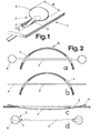
- FIG. 1 shows a composite of a sheet stack 1 made of a plurality of sheets made of flat material, namely of paper, which is held together by a connecting element 2.
- the connecting element 2 consists essentially of a web 3 and two holding members 4, which are formed in the form of widenings on the two ends of the web 3.
- the thickness of the holding members 4 essentially corresponds the thickness of the web 3, while the plan of the holding members 4 has significantly larger dimensions than the cross-sectional dimensions of the web 3.
- the web 3 is connected on the edge to the holding members 4, coplanar with them and made in one piece from elastomeric material.
- the sheets brought together to form the sheet stack 1 have recesses in the form of elongated holes 5 at a predetermined (and of course matching) spacing, only one of which is shown in FIG. 1.
- the width b of the elongated holes 5 is significantly smaller than the width B of the holding members 4, as can be easily seen from FIG. 1.
- the web 3 runs through the elongated holes 5 and accordingly has smaller cross-sectional dimensions, while the holding members 4 lie essentially parallel to the sheet stack 1.
- the elongated holes 5 lie with their longitudinal extension in the direction of their connecting ends and thus simultaneously in the direction of the web 3.
- the manufacture of the composite shown in FIG. 1 is explained in detail with reference to FIG. 2.
- the sheet stack 1 is first bent by a direction perpendicular to the connecting end of the elongated holes 5 as far as is necessary to insert the connecting element 2 through the elongated holes 5 (FIG. 2a).
- the connecting elements 2 are in a position parallel to the longitudinal extension of the elongated holes 5 and perpendicular to the sheet stack.
- the connecting element 2 is then rotated as a whole about the longitudinal axis of the web 3 by approximately 90 degrees (FIG. 2b).
- the sheet stack 1 is placed flat thereon, the web 3 running in a slight arc through the elongated holes 5 and the connecting elements 2 lying approximately parallel to the top of the sheet stack 1 (FIG. 2c).
- Figure 2 d shows a top view of the finished composite and shows how the connecting elements 2 protrude laterally beyond the elongated holes 5 and are thereby held.
- the removal of the connecting element 2 for releasing the composite is carried out accordingly in the reverse order.
- FIG. 3 shows an embodiment which corresponds essentially to the subject of FIG. 1, but in which the elongated holes 5 are arranged differently, namely with their longitudinal extension perpendicular to the direction of their connecting ends and thus perpendicular to the web 3 of the connecting element 2.
- the web 3 is connected to the base of the holding members 4, so that a "dumbbell-like" shape results.
- the manufacture of the composite according to FIG. 3 is shown in individual steps in FIG. 4. First, the sheet stack 1 is bent so far about a direction perpendicular to the connecting end of the elongated holes 5 that the connecting element 2 can be inserted through the elongated holes 5 (FIG. 4a).
- FIG. 4d shows a top view of the configuration according to FIG. 4c. It can be seen that - as far as in the case of FIG. 2d - the web runs on the underside of the sheet stack 1 and the holding members 4 are held on the top by protruding the elongated holes 5 on both sides. The bond is released in reverse order.
- the web consists generally and also in the illustrated embodiments of a material of good flexibility and relatively small thickness, so that it easily adapts to the course given by the elongated holes 5 without causing the sheet stack 1 to bend.
- FIG. 5a shows an exemplary embodiment in which the holding members 4 are opposite Web 3 are inclined by the same acute angle in opposite directions, so that - in particular in the case of thicker sheet stacks - the holding members 4 lie flat on the upper side, while the web 3 is guided in an arc through the elongated holes 5.
- This embodiment can also be inserted through the elongated holes 5 in a particularly simple manner (cf. FIG. 4 a).
- a correspondingly inclined arrangement of web 3 and holding members 4 is of course also possible in the embodiment according to FIGS. 1 and 2.
- FIG. 5b shows an embodiment in which the web 3 is formed from a plastic monofilament and at the end is cast or glued into the holding members 4 made of rigid plastic material. This can of course also be achieved in a corresponding manner in an embodiment according to FIGS. 1 and 2.
- Figure 5c shows an embodiment that is particularly recommended for thick sheet stacks.
- the web 3 is designed to be divisible, one of the two web parts having an integrally formed sleeve 6 and the other web part having an integrally formed clamping pin 7.
- FIGS. 2 and 4 a procedure according to FIGS. 2 and 4 can prove to be difficult.
- the embodiment shown in FIG. 5c offers the possibility of inserting the two halves of the connecting element 2 through one of the elongated holes and then connecting them together by joining the sleeve 6 and the clamping pin 7.
- Sleeve 6 and pin 7 are formed in a manner known per se so that they can be locked together.
- FIG. 5c it is necessary to establish the bond between the two connecting links on the underside of the sheet stack.
- the job due to the thickness of the connecting links can interfere.
- FIG. 5d the embodiment shown in FIG. 5d is recommended, in which the connecting links are laid directly on one of the two holding links 4.
- the holding member 4 has on its underside a buckle-like passage 8 through which the web 3 designed as a flat belt is passed.
- the holding member 4 can be moved with the passage 8 on the web 3, a clamping being achieved by appropriate dimensioning of the web 3 and passage 8, by means of which the holding member 4 is held in the position provided in each case.
- a locking mechanism in a manner known per se, for example in the form of a sawtooth profile on the web 3 and a tongue arranged in the passage 8.
- This embodiment can be implemented both in the "paddle shape” according to FIGS. 1 and 2 and in the "dumbbell shape” according to FIGS. 3 and 4.
- this embodiment offers the significant advantage that the effective length of the web 3 can be adapted to the respective thickness of the sheet stack.
- This embodiment can of course first be applied in the manner explained in connection with FIGS. 2 and 4.
- a further possibility, which may be advantageous in particular in the case of thick stacks of sheets, is to first only thread the web 3 through the elongated holes and then to attach the holding member 4 provided with the passage 8.
- a connecting element according to the invention described above on the basis of various exemplary embodiments will often be formed symmetrically with holding members 4 of identical design in terms of their dimensions. From the above description, however, it is readily apparent that it is sufficient for producing the composite if only one of the two holding members 4 is designed with respect to its cross-sectional dimensions so that it can be inserted through the elongated holes 5. So that exists in many cases Particularly advantageous possibility of making the other holding member 4 larger and in particular so large that it cannot be inserted through the elongated holes 5. If use is made of this possibility (not shown in the figures), the larger holding member or the like can be used in a particularly advantageous manner as a label carrier. be formed.
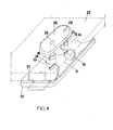
- 11 denotes the plate-shaped foot, on the underside of which a collecting box 12 is attached in a conventional manner for receiving the punched-out plates.
- the foot 11, which serves as a cutting plate, is provided with through openings 13 which cooperate with the cutting punches to be described later.
- Attached to the foot are the brackets 14, which are approximately angular in cross-section and whose free legs protrude beyond the foot 11.
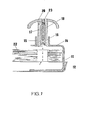
- the cutting punches 17, which work against the action of springs 18, are arranged displaceably in the guides 15.
- the cutting punches 17 have recesses 19 suf, through which the transverse pins 16 pass.
- the inner circumferences of the passage openings 13 and the outer circumferential surfaces of the cutting punches 17 correspond to one another in shape and have an elongated shape, so that the holes produced are shaped like an elongated hole.
- a pressure plate 20 is arranged, which serves as a support for one hand.
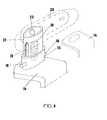
- a stop 21 which can have the shape of a bracket, as can be seen in FIG. 6.
- the stop 21 it is also possible for the stop 21 to be formed by two pins, as can be seen in FIG.
- brackets 14 can be slidably attached to the foot 21, so that a different distance between the two holes is possible.
- the pressure plate 20 is fastened to the free ends of the cutting punches 17 by means of screws 23, so that the cutting punches 17 can be removed from their guides 15 by loosening the screws 23.
- the undersides of the cutting punch 17 are cut concave in order to achieve a good cutting effect.
- the inner circumferential surfaces of the passage openings and the outer circumferential surfaces of the cutting elements which are adapted to them can generally have shapes that deviate from a circular shape, for example oval, diamond, deltoid or the like. be trained.
Landscapes
- Life Sciences & Earth Sciences (AREA)
- Forests & Forestry (AREA)
- Engineering & Computer Science (AREA)
- Mechanical Engineering (AREA)
- Laminated Bodies (AREA)
Applications Claiming Priority (4)
| Application Number | Priority Date | Filing Date | Title |
|---|---|---|---|
| DE3005878 | 1980-02-16 | ||
| DE19803005878 DE3005878C2 (de) | 1980-02-16 | 1980-02-16 | Verbund einer Mehrzahl von durch ein Verbindungselement zusammengehaltenen Blättern |
| DE8103970U | 1981-02-13 | ||
| DE19818103970 DE8103970U1 (de) | 1981-02-13 | 1981-02-13 | Vorrichtung zur einstanzung von mindestens zwei lochungen in ein oder mehrere blaetter |
Publications (1)
| Publication Number | Publication Date |
|---|---|
| EP0035149A1 true EP0035149A1 (fr) | 1981-09-09 |
Family
ID=25783772
Family Applications (1)
| Application Number | Title | Priority Date | Filing Date |
|---|---|---|---|
| EP81101039A Ceased EP0035149A1 (fr) | 1980-02-16 | 1981-02-14 | Assemblage de feuilles reliées par un élément d'assemblage |
Country Status (1)
| Country | Link |
|---|---|
| EP (1) | EP0035149A1 (fr) |
Cited By (1)
| Publication number | Priority date | Publication date | Assignee | Title |
|---|---|---|---|---|
| FR2780680A1 (fr) * | 1998-07-03 | 2000-01-07 | Jean Yves Dauvergne | Systeme de reliure sans machine permettant une ouverture a plat et la personnalisation |
Citations (15)
| Publication number | Priority date | Publication date | Assignee | Title |
|---|---|---|---|---|
| FR665999A (fr) * | 1900-01-01 | |||
| FR517027A (fr) * | 1920-06-11 | 1921-04-29 | Lennox Liddell | Perfectionnements aux appareils servant à perforer le papier |
| DE408859C (de) * | 1921-08-20 | 1925-01-29 | Georg Hoehn | In einem Schlitz der zu heftenden Gegenstaende anzubringende biegsame Klammer mit verbreiterten Enden zum Vereinigen von Papierblaettern o. dgl. |
| FR609105A (fr) * | 1926-01-11 | 1926-08-09 | Dispositif pour perforer le papier | |
| GB343562A (en) * | 1929-11-21 | 1931-02-23 | Christopher Henry Ellis | Improvements in or relating to loose-leaf binders or files |
| GB394334A (en) * | 1931-12-21 | 1933-06-21 | Ernest Alfred Boom | Improvements in fasteners for loose leaf binders |
| GB565863A (en) * | 1943-01-14 | 1944-12-01 | Viktor Persson | Improvements in fastening means for assembling perforated sheets and the like |
| US2587185A (en) * | 1946-09-17 | 1952-02-26 | Allan O Marsh | Multiple punch |
| FR1255587A (fr) * | 1960-03-16 | 1961-03-10 | Leitz Fa Louis | Classeur pour documents perforés avec système d'alignement interchangeable constitué par une ou deux bandes élastiques |
| DE1842835U (de) * | 1961-08-11 | 1961-12-07 | Karl Bartsch | Locher, insbesondere fuer papier. |
| DE1197434B (de) * | 1960-07-15 | 1965-07-29 | Soennecken Fa F | Aufreihvorrichtung fuer Schnellhefter |
| US3246653A (en) * | 1962-08-09 | 1966-04-19 | Sexton William Wait | Binder for perforated leaves |
| FR1512416A (fr) * | 1966-12-22 | 1968-02-09 | Reliure pour documents se présentant sous la forme d'une liasse | |
| US3408889A (en) * | 1965-08-25 | 1968-11-05 | Intex Oil Company | File folder punch |
| BE867953A (nl) * | 1978-06-08 | 1978-12-08 | Japdok Internat Establishment | Perforator met een reeks smalle en een reeks brede stansstukken |
-
1981
- 1981-02-14 EP EP81101039A patent/EP0035149A1/fr not_active Ceased
Patent Citations (15)
| Publication number | Priority date | Publication date | Assignee | Title |
|---|---|---|---|---|
| FR665999A (fr) * | 1900-01-01 | |||
| FR517027A (fr) * | 1920-06-11 | 1921-04-29 | Lennox Liddell | Perfectionnements aux appareils servant à perforer le papier |
| DE408859C (de) * | 1921-08-20 | 1925-01-29 | Georg Hoehn | In einem Schlitz der zu heftenden Gegenstaende anzubringende biegsame Klammer mit verbreiterten Enden zum Vereinigen von Papierblaettern o. dgl. |
| FR609105A (fr) * | 1926-01-11 | 1926-08-09 | Dispositif pour perforer le papier | |
| GB343562A (en) * | 1929-11-21 | 1931-02-23 | Christopher Henry Ellis | Improvements in or relating to loose-leaf binders or files |
| GB394334A (en) * | 1931-12-21 | 1933-06-21 | Ernest Alfred Boom | Improvements in fasteners for loose leaf binders |
| GB565863A (en) * | 1943-01-14 | 1944-12-01 | Viktor Persson | Improvements in fastening means for assembling perforated sheets and the like |
| US2587185A (en) * | 1946-09-17 | 1952-02-26 | Allan O Marsh | Multiple punch |
| FR1255587A (fr) * | 1960-03-16 | 1961-03-10 | Leitz Fa Louis | Classeur pour documents perforés avec système d'alignement interchangeable constitué par une ou deux bandes élastiques |
| DE1197434B (de) * | 1960-07-15 | 1965-07-29 | Soennecken Fa F | Aufreihvorrichtung fuer Schnellhefter |
| DE1842835U (de) * | 1961-08-11 | 1961-12-07 | Karl Bartsch | Locher, insbesondere fuer papier. |
| US3246653A (en) * | 1962-08-09 | 1966-04-19 | Sexton William Wait | Binder for perforated leaves |
| US3408889A (en) * | 1965-08-25 | 1968-11-05 | Intex Oil Company | File folder punch |
| FR1512416A (fr) * | 1966-12-22 | 1968-02-09 | Reliure pour documents se présentant sous la forme d'une liasse | |
| BE867953A (nl) * | 1978-06-08 | 1978-12-08 | Japdok Internat Establishment | Perforator met een reeks smalle en een reeks brede stansstukken |
Cited By (1)
| Publication number | Priority date | Publication date | Assignee | Title |
|---|---|---|---|---|
| FR2780680A1 (fr) * | 1998-07-03 | 2000-01-07 | Jean Yves Dauvergne | Systeme de reliure sans machine permettant une ouverture a plat et la personnalisation |
Similar Documents
| Publication | Publication Date | Title |
|---|---|---|
| DE3786292T2 (de) | Verfahren zum Binden von Büchern, Ordner für Papierbögen und einstellbarer Rücken. | |
| EP0011819B1 (fr) | Elément d'une reliure | |
| DE2422023A1 (de) | Brieflocher | |
| DE2302365B2 (de) | Aufreihsystem für gelochte Papierstapel od. dgl. in Heftern, Mappen und ähnlichen Registratursammlern | |
| DE2907656C2 (fr) | ||
| DE3023843A1 (de) | Vorrichtung zum heften eines stapels von papierblaettern, papierboegen o.dgl. | |
| EP0499152A1 (fr) | Classeur ou similaire | |
| DE69100839T2 (de) | Bindeelement für papierbogen mit zweierlei orientierung von aufreihstiften. | |
| DE2656021C3 (de) | Briefordner zur Aufnahme von gelochtem Schriftgut | |
| DE2206662B2 (de) | Blatthalter | |
| DE3005878C2 (de) | Verbund einer Mehrzahl von durch ein Verbindungselement zusammengehaltenen Blättern | |
| EP0158002B1 (fr) | Dispositif pour l'assemblage de matériaux en feuille | |
| DE3227301C2 (de) | Einrichtung zum Lochen | |
| DE2647044A1 (de) | Aufreihvorrichtung fuer loses schriftgut | |
| DE102004045611B3 (de) | Aufhänger zum Aufhängen von Gegenständen an ebenen Flächen | |
| EP0654362B1 (fr) | Dispositif de reliure pour relier et déposer des piles de substrats | |
| DE19629801C2 (de) | Heftstreifen | |
| DE8103970U1 (de) | Vorrichtung zur einstanzung von mindestens zwei lochungen in ein oder mehrere blaetter | |
| DE102006006479B4 (de) | Klebeheftelement | |
| DE9401631U1 (de) | Einhänge-Heftstreifen | |
| DE1127329B (de) | Aufreihvorrichtung aus schliessbaren Einzelringen zum Zusammenschliessen von Loseblaettern | |
| DE8702107U1 (de) | Vorrichtung zum Abheften gelochter Blätter | |
| DE2656695C2 (de) | Heftvorrichtung für gelochte Papiere | |
| DE2243537A1 (de) | Schnellhefter mit aufreiheinrichtung fuer gelochtes schriftgut | |
| DE3415985A1 (de) | Locherauflagevorrichtung |
Legal Events
| Date | Code | Title | Description |
|---|---|---|---|
| PUAI | Public reference made under article 153(3) epc to a published international application that has entered the european phase |
Free format text: ORIGINAL CODE: 0009012 |
|
| AK | Designated contracting states |
Designated state(s): AT BE CH FR GB IT NL SE |
|
| 17P | Request for examination filed |
Effective date: 19820226 |
|
| STAA | Information on the status of an ep patent application or granted ep patent |
Free format text: STATUS: THE APPLICATION HAS BEEN REFUSED |
|
| 18R | Application refused |
Effective date: 19851215 |