EP0035277A1 - Système de transmission séquentiel pour le branchement sans adresse de plusieurs abonnés à un central - Google Patents
Système de transmission séquentiel pour le branchement sans adresse de plusieurs abonnés à un central Download PDFInfo
- Publication number
- EP0035277A1 EP0035277A1 EP81101550A EP81101550A EP0035277A1 EP 0035277 A1 EP0035277 A1 EP 0035277A1 EP 81101550 A EP81101550 A EP 81101550A EP 81101550 A EP81101550 A EP 81101550A EP 0035277 A1 EP0035277 A1 EP 0035277A1
- Authority
- EP
- European Patent Office
- Prior art keywords
- transmission system
- subscriber
- switch
- bus
- control logic
- Prior art date
- Legal status (The legal status is an assumption and is not a legal conclusion. Google has not performed a legal analysis and makes no representation as to the accuracy of the status listed.)
- Withdrawn
Links
Images



Classifications
-
- H—ELECTRICITY
- H04—ELECTRIC COMMUNICATION TECHNIQUE
- H04L—TRANSMISSION OF DIGITAL INFORMATION, e.g. TELEGRAPHIC COMMUNICATION
- H04L12/00—Data switching networks
- H04L12/28—Data switching networks characterised by path configuration, e.g. LAN [Local Area Networks] or WAN [Wide Area Networks]
- H04L12/40—Bus networks
- H04L12/40006—Architecture of a communication node
- H04L12/40032—Details regarding a bus interface enhancer
-
- G—PHYSICS
- G08—SIGNALLING
- G08B—SIGNALLING SYSTEMS, e.g. PERSONAL CALLING SYSTEMS; ORDER TELEGRAPHS; ALARM SYSTEMS
- G08B26/00—Alarm systems in which substations are interrogated in succession by a central station
- G08B26/005—Alarm systems in which substations are interrogated in succession by a central station with substations connected in series, e.g. cascade
-
- H—ELECTRICITY
- H04—ELECTRIC COMMUNICATION TECHNIQUE
- H04L—TRANSMISSION OF DIGITAL INFORMATION, e.g. TELEGRAPHIC COMMUNICATION
- H04L12/00—Data switching networks
- H04L12/28—Data switching networks characterised by path configuration, e.g. LAN [Local Area Networks] or WAN [Wide Area Networks]
- H04L12/40—Bus networks
- H04L12/403—Bus networks with centralised control, e.g. polling
-
- H—ELECTRICITY
- H04—ELECTRIC COMMUNICATION TECHNIQUE
- H04Q—SELECTING
- H04Q9/00—Arrangements in telecontrol or telemetry systems for selectively calling a substation from a main station, in which substation desired apparatus is selected for applying a control signal thereto or for obtaining measured values therefrom
Definitions
- the invention relates to a transmission system for connecting a plurality of subscribers to a control center via a common connecting link, which is referred to below as the "peripheral bus". Participants can be either data sources or data sinks; the peripheral bus is preferably a two-wire connection.
- the invention has for its object to avoid the installation effort shown and in particular to show a technical possibility for addressless connection of several participants to a peripheral bus leading to a control center.
- Participants include sensors such as temperature sensors, smoke detectors and the same as data sources and actuators, such as valves, signal transmitters and the like understood as data sinks.
- the invention provides for each subscriber to be assigned at least two switch elements which can be actuated by a control logic, one of which is connected in series to the subscriber to be connected to the control center and the other lies directly in the course of one wire of the bus, so that the wire in question is interrupted. when the switch element opens. It is important within the inventive concept that the switch elements of a switch pair are never closed at the same time for each subscriber.
- the order or selection of the individual participants is given by their order on the bus. This ranking is made clear by the fact that, for example, in the case of a two-wire line, one of the two bus conductors is interrupted for each participant.
- the timing for switching from one participant to the next can be carried out both centrally and decentrally.
- Central control is understood to mean that the sequential connection of the participants on the bus is determined by sequential control signals from the control center.
- decentralized control either an activation of the individual control logics of the participants from the outside or an activation of the first participant on the bus from the outside or from the central, for example by switching on the supply voltage which is also possible via the bus Participants, understood.
- the activation of the other participants then takes place sequentially, for example with the closing of the switch element located in a bus conductor, the individual participants determining the chronological order and duration of their connection to the bus by using timers themselves, so that after the switch-on time for a first one When the switch element in one core of the peripheral bus is closed, the connection time for the next participant begins.
- FIG. 2 shows with its three sub-figures 2a, 2b and 2c the basic design of a subscriber with switch pairs symbolically represented as contacts, which can be technically implemented, for example, by FET switches.
- the switch S 1 of each switch pair is closed and the switch S 2 is open in each case.
- This state also initially exists when the central control unit is activated, which is described in more detail below.
- switch S 2 closes and switch 5 1 opens, so that the path to the next subscriber is cleared and the connection of the subscriber previously switched on is interrupted.
- FIG. 3 The circuit example of FIG. 3 for the switch pair assigned to a subscriber with control logic with central control shows the switches S 1 , S 2 of the switch pair realized as VMOS-FETs, the control logic 4 with RC element 5, which is implemented as a CMOS flip-flop determines the astable service life of the CMOS flip-flop 4, and the subscriber 6, which is generally shown as a current source.
- the connection of the subscriber 6 to the bus 2, 3, determined by the astable service life of the flip-flop 4, takes place as follows:
- an input voltage U E ' is applied, which can be done, for example, by switching on the supply voltage at the control center, the flip-flop 4 is set (or remains in its idle state) such that the participant 6 is in the circuit, that is, the switch element S 1 is closed, that is switched to continuity.
- the flip-flop 4 is implemented under the action of the RC element by a short pulse, for example by a brief interruption of U E , as a result of which the switch element S 1 is now opened and the switch element S 2 is closed. This switches U E through to the output (U A ).
- the subscriber 6 is thus separated from the bus 2, 3, but the supply of the flip-flop 4 remains secured.
- the residual current flowing through the subscriber-related logic is negligible, especially if - as indicated - the flip-flop 4 is implemented in CMOS technology.
- time counters can also be used to determine the delay time.
- an individual setting of the delay time can be simplified depending on the application conditions.
- An active module 10 for example a Schmitt trigger or an operational amplifier, can be preceded by an RC element, the measurement of which is the delay between one Input signal A and an output signal B determined.
- a microprocessor system triggers a voltage control 14 in the manner explained in more detail below with reference to FIG. 11 at the beginning of a measurement program sequence, by means of which a switch S 3 is activated , so that a voltage U A is applied from a supply source 15 between the two lines 2, 3 of the bus.
- Transmissions to the individual subscribers can be triggered by modulating the output voltage, while information can be exchanged from the subscribers to the control center by detecting the current flowing over the pair of lines.
- the selection of the participants is not arbitrary, but takes place in the order in which they are arranged on the bus.
- the diagram in FIG. 7 shows the signal course over time on the peripheral bus in the case of decentralized control, it being possible for each subscriber to contain control logic which corresponds in structure to that of FIG. 4.
- the center determines, for example, by switching on the supply voltage at time t 1, the query of the first participant whose switch element S 1 1 is closed and whose switch S 2 1 is open (cf. FIG. 2a in connection with FIG. 4).
- the delay time of the first delay element 8 has expired, so that the switch S 1 1 opens and the switch S 2 1 remains open.
- the delay time of delay element 9 has expired.
- the switch element S 1 1 remains open and the switch element S 2 1 closes, so that the activation of the second participant on the bus takes place while the query of the first participant has already been completed.
- the other participants on the bus are interrogated in an analogous manner, which can be seen from the time diagram in FIG. 7 without further explanation.
- the switch S 1 N of the subscriber T N opens, which means that the last subscriber on the bus has been queried.
- the control center switches off the supply voltage again, so that the idle or initial state is reached again for all participants.
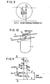
- FIG. 9 shows a particularly simple special case for a peripheral bus, which only has to transmit information from the subscriber to the control center.
- the low pass 13 of FIG. 8 can be omitted here.
- the connection of the supply voltage also serves as a signal for the start of the chain-like query of the individual participants. It only has to be ensured that the power supply is also possible during an input process.
- An example of this embodiment of the invention is the so-called sensor bus, which comprises a number of spatially arranged sensors, e.g. Connects the temperature sensor to a control center.
- FIG. 9 shows such a simple subscriber, the control circuit shown, which is fed by the signal line, in turn carrying out the switching tasks specified with reference to FIG. 2.
- the control logic will be implemented, for example, as a flip-flop (cf. FIG. 3) and with decentralized control, for example, by timing elements (cf. FIG. 4). In both cases, the control circuit is again so low-power that its own consumption does not noticeably affect an analog signal on the line.
- All known sensors and digital transmitters for interrogation can be connected to such a sensor bus in a simple manner and the control logic for bus connection can be implemented in a simple integrated circuit.
- the installation of the individual sensors with assigned control logic can be implemented with a single handle using a special tool.
- the order of the participants on the sensor bus 2, 3 is communicated to the control center 12, for example by programming (manual input). Faults on the bus either work through short interference pulses or as a result of a network hum. In this case, the errors can be largely eliminated by averaging the measurement signal over a longer period of time.
Landscapes
- Engineering & Computer Science (AREA)
- Computer Networks & Wireless Communication (AREA)
- Signal Processing (AREA)
- Business, Economics & Management (AREA)
- Emergency Management (AREA)
- Physics & Mathematics (AREA)
- General Physics & Mathematics (AREA)
- Small-Scale Networks (AREA)
- Selective Calling Equipment (AREA)
- Interface Circuits In Exchanges (AREA)
Applications Claiming Priority (2)
| Application Number | Priority Date | Filing Date | Title |
|---|---|---|---|
| DE3008450 | 1980-03-05 | ||
| DE19803008450 DE3008450C2 (de) | 1980-03-05 | 1980-03-05 | Sequentielles Übertragungssystem zum adressenlosen Anschließen mehrerer Teilnehmer an eine Zentrale |
Publications (1)
| Publication Number | Publication Date |
|---|---|
| EP0035277A1 true EP0035277A1 (fr) | 1981-09-09 |
Family
ID=6096351
Family Applications (1)
| Application Number | Title | Priority Date | Filing Date |
|---|---|---|---|
| EP81101550A Withdrawn EP0035277A1 (fr) | 1980-03-05 | 1981-03-04 | Système de transmission séquentiel pour le branchement sans adresse de plusieurs abonnés à un central |
Country Status (2)
| Country | Link |
|---|---|
| EP (1) | EP0035277A1 (fr) |
| DE (1) | DE3008450C2 (fr) |
Cited By (9)
| Publication number | Priority date | Publication date | Assignee | Title |
|---|---|---|---|---|
| EP0076586A1 (fr) * | 1981-09-18 | 1983-04-13 | RAYCHEM CORPORATION (a California corporation) | Appareillage de contrôle monté en cascade |
| EP0088067A1 (fr) * | 1982-02-25 | 1983-09-07 | CIFCO Société Anonyme | Procédé de télémesure, télésignalisation et télécommande applicable en particulier à la détection d'incendie et d'intrusion et à l'éclairage |
| EP0111178A1 (fr) * | 1982-11-23 | 1984-06-20 | Cerberus Ag | Dispositif de contrôle avec plusieurs détecteurs connectés, en forme de chaîne, à une ligne de signalisation |
| EP0212106A1 (fr) * | 1985-07-10 | 1987-03-04 | Cerberus Ag | Méthode de transmission de valeurs de mesure |
| WO1990001245A1 (fr) * | 1988-07-27 | 1990-02-08 | Peter Vockenhuber | Agencement d'adressage |
| EP0450119A1 (fr) * | 1990-04-03 | 1991-10-09 | Siemens Aktiengesellschaft | Dispositif pour raccorder des éléments additionnels à une ligne servant à la surveillance et déjà existante |
| WO1997045983A1 (fr) * | 1996-05-25 | 1997-12-04 | Robert Bosch Gmbh | Dispositif d'adressage pour poste repetiteur d'un systeme bus seriel et procede d'adressage d'un poste repetiteur |
| WO2005024749A3 (fr) * | 2003-09-11 | 2005-04-28 | Bosch Gmbh Robert | Detecteur, dispositif de commande et procede d'exploitation de detecteurs relies a un dispositif de commande |
| WO2011054458A1 (fr) * | 2009-10-26 | 2011-05-12 | Phoenix Contact Gbmh & Co. Kg | Système de communication de sécurité pour signaler des états du système |
Families Citing this family (3)
| Publication number | Priority date | Publication date | Assignee | Title |
|---|---|---|---|---|
| DE3812655A1 (de) * | 1988-04-15 | 1989-10-26 | Langlechner Richard Gmbh | Vorrichtung zur anwahl von stationen, die mit einer steuerungszentrale verbunden sind |
| DE4328932C2 (de) * | 1993-08-27 | 1998-10-15 | Busch Dieter & Co Prueftech | Verfahren und Einrichtung für die Fernabfrage von Meßstellen |
| DE19959710A1 (de) * | 1999-12-10 | 2001-06-21 | Siemens Ag | Verfahren zum Übertragen der Ausgangssignale mehrerer Sensoreinheiten sowie elektronisches Steuersystem und Sensoreinheit |
Citations (1)
| Publication number | Priority date | Publication date | Assignee | Title |
|---|---|---|---|---|
| DE1197513B (de) * | 1961-05-26 | 1965-07-29 | Ibm | Schaltungsanordnung zum wahlweisen Ver-binden von Unterstationen mit einer Zentral-station in Fernmeldeanlagen |
Family Cites Families (4)
| Publication number | Priority date | Publication date | Assignee | Title |
|---|---|---|---|---|
| CH550521A (de) * | 1972-07-04 | 1974-06-14 | Hasler Ag | Verfahren zur nachrichtenuebertragung zwischen teilnehmerstellen. |
| DE2517097A1 (de) * | 1975-04-18 | 1976-10-28 | Licentia Gmbh | Verfahren zur nachrichtenuebertragung |
| DE2528840B2 (de) * | 1975-06-27 | 1977-09-01 | Siemens AG 1000 Berlin und 8000 München | Verfahren zum betrieb eines pcm- zeitmultiplexfernmeldenetzes mit digital arbeitenden teilnehmerendstellen |
| DE2659533C2 (de) * | 1976-12-30 | 1984-04-26 | ANT Nachrichtentechnik GmbH, 7150 Backnang | Verfahren zur Nachrichtenübertragung in einem Fernmeldesystem mit einer Vielzahl von Teilnehmerstationen |
-
1980
- 1980-03-05 DE DE19803008450 patent/DE3008450C2/de not_active Expired
-
1981
- 1981-03-04 EP EP81101550A patent/EP0035277A1/fr not_active Withdrawn
Patent Citations (1)
| Publication number | Priority date | Publication date | Assignee | Title |
|---|---|---|---|---|
| DE1197513B (de) * | 1961-05-26 | 1965-07-29 | Ibm | Schaltungsanordnung zum wahlweisen Ver-binden von Unterstationen mit einer Zentral-station in Fernmeldeanlagen |
Non-Patent Citations (1)
| Title |
|---|
| IBM Technical Disclosure Bulletin, Band 9, Nr. 10, Marz 1967, seite 1293 New York, U.S.A. M.M. ASTRAHAN et al.: "Pulse Initiated Polling System" * insgesamt * * |
Cited By (10)
| Publication number | Priority date | Publication date | Assignee | Title |
|---|---|---|---|---|
| EP0076586A1 (fr) * | 1981-09-18 | 1983-04-13 | RAYCHEM CORPORATION (a California corporation) | Appareillage de contrôle monté en cascade |
| EP0088067A1 (fr) * | 1982-02-25 | 1983-09-07 | CIFCO Société Anonyme | Procédé de télémesure, télésignalisation et télécommande applicable en particulier à la détection d'incendie et d'intrusion et à l'éclairage |
| EP0111178A1 (fr) * | 1982-11-23 | 1984-06-20 | Cerberus Ag | Dispositif de contrôle avec plusieurs détecteurs connectés, en forme de chaîne, à une ligne de signalisation |
| US4568919A (en) * | 1982-11-23 | 1986-02-04 | Cerberus Ag | Monitoring system including a number of measuring stations series connected to a signal line |
| EP0212106A1 (fr) * | 1985-07-10 | 1987-03-04 | Cerberus Ag | Méthode de transmission de valeurs de mesure |
| WO1990001245A1 (fr) * | 1988-07-27 | 1990-02-08 | Peter Vockenhuber | Agencement d'adressage |
| EP0450119A1 (fr) * | 1990-04-03 | 1991-10-09 | Siemens Aktiengesellschaft | Dispositif pour raccorder des éléments additionnels à une ligne servant à la surveillance et déjà existante |
| WO1997045983A1 (fr) * | 1996-05-25 | 1997-12-04 | Robert Bosch Gmbh | Dispositif d'adressage pour poste repetiteur d'un systeme bus seriel et procede d'adressage d'un poste repetiteur |
| WO2005024749A3 (fr) * | 2003-09-11 | 2005-04-28 | Bosch Gmbh Robert | Detecteur, dispositif de commande et procede d'exploitation de detecteurs relies a un dispositif de commande |
| WO2011054458A1 (fr) * | 2009-10-26 | 2011-05-12 | Phoenix Contact Gbmh & Co. Kg | Système de communication de sécurité pour signaler des états du système |
Also Published As
| Publication number | Publication date |
|---|---|
| DE3008450A1 (de) | 1981-09-10 |
| DE3008450C2 (de) | 1986-09-18 |
Similar Documents
| Publication | Publication Date | Title |
|---|---|---|
| DE3236812C2 (de) | Fernwirksystem | |
| EP1206765B1 (fr) | Procede et dispositif d'affectation automatique d'adresses de detecteurs dans un systeme avertisseur de danger | |
| DE3329049C2 (fr) | ||
| DE3110836C2 (de) | Eingangs-Schnittstelleneinheit für eine programmierbare logische Steuereinheit | |
| DE2817089B2 (de) | Gefahrenmeldeanlage | |
| EP0393233B1 (fr) | Système de transmission de signaux | |
| DE3008450C2 (de) | Sequentielles Übertragungssystem zum adressenlosen Anschließen mehrerer Teilnehmer an eine Zentrale | |
| DE2521388A1 (de) | Schaltungsanordnung zur uebertragung digitaler daten | |
| DE2817121C2 (de) | Gefahrenmeldeanlage | |
| DE2725250C3 (de) | Kabelfernsehanlage mit abschaltbaren Teilnehmeranschlüssen | |
| DE19515633A1 (de) | Elektroinstallation für ein Gebäude | |
| DE3424294A1 (de) | Abfrageeinrichtung zur identifikation der stellung von schaltern | |
| EP0004912B1 (fr) | Avertisseur de danger | |
| DE2924291A1 (de) | Digitaler signalgeber-empfaenger mit selbstkontrolle | |
| EP0098554B1 (fr) | Procédé et dispositif pour la demande automatique des valeurs de mesure de signalisation et de l'identificateur de signalisation dans une installation d'avertisseur d'alarme | |
| DE19631302B4 (de) | Sensor-Aktor-Bussystem | |
| EP0098552B1 (fr) | Procédé et dispositif pour la demande automatique des valeurs de mesure de signalisation et de l'identificateur de signalisation dans une installation d'avertisseur d'alarme | |
| WO2007017073A2 (fr) | Systeme de controle automatique de batiments ou systeme avertisseur de danger | |
| DE3230761C2 (fr) | ||
| DE102005043489A1 (de) | Automatisierungstechnische Einrichtung | |
| DE102019003206B3 (de) | Sicherheitsanordnung | |
| DE3610246A1 (de) | Ueberwachungssystem | |
| DE3225032C2 (de) | Verfahren und Einrichtung zur wahlweisen automatischen Abfrage der Melderkennung oder des Meldermeßwerts in einer Gefahrenmeldeanlage | |
| EP0098553B1 (fr) | Procédé et dispositif pour la demande automatique des valeurs de mesure de signalisation et/ou de l'identificateur de signalisation dans une installation d'avertisseur d'alarme | |
| DE19606896C2 (de) | Schaltung zum Stellen und Überwachen von Lichtsignalen |
Legal Events
| Date | Code | Title | Description |
|---|---|---|---|
| PUAI | Public reference made under article 153(3) epc to a published international application that has entered the european phase |
Free format text: ORIGINAL CODE: 0009012 |
|
| AK | Designated contracting states |
Designated state(s): FR GB IT NL |
|
| STAA | Information on the status of an ep patent application or granted ep patent |
Free format text: STATUS: THE APPLICATION IS DEEMED TO BE WITHDRAWN |
|
| 18D | Application deemed to be withdrawn |
Effective date: 19820816 |