EP0035283A1 - Accouplement d'arbres - Google Patents
Accouplement d'arbres Download PDFInfo
- Publication number
- EP0035283A1 EP0035283A1 EP81102035A EP81102035A EP0035283A1 EP 0035283 A1 EP0035283 A1 EP 0035283A1 EP 81102035 A EP81102035 A EP 81102035A EP 81102035 A EP81102035 A EP 81102035A EP 0035283 A1 EP0035283 A1 EP 0035283A1
- Authority
- EP
- European Patent Office
- Prior art keywords
- shaft coupling
- coupling according
- link
- bead
- links
- Prior art date
- Legal status (The legal status is an assumption and is not a legal conclusion. Google has not performed a legal analysis and makes no representation as to the accuracy of the status listed.)
- Granted
Links
- 230000008878 coupling Effects 0.000 title claims abstract description 182
- 238000010168 coupling process Methods 0.000 title claims abstract description 182
- 238000005859 coupling reaction Methods 0.000 title claims abstract description 182
- 239000011324 bead Substances 0.000 claims description 78
- 239000002184 metal Substances 0.000 claims description 7
- 239000000314 lubricant Substances 0.000 claims description 6
- 125000006850 spacer group Chemical group 0.000 claims description 6
- 239000003638 chemical reducing agent Substances 0.000 claims description 5
- 230000006835 compression Effects 0.000 claims description 3
- 238000007906 compression Methods 0.000 claims description 3
- 239000011248 coating agent Substances 0.000 claims description 2
- 238000000576 coating method Methods 0.000 claims description 2
- 238000006073 displacement reaction Methods 0.000 abstract description 4
- 230000005540 biological transmission Effects 0.000 description 13
- 239000000123 paper Substances 0.000 description 7
- 244000089486 Phragmites australis subsp australis Species 0.000 description 6
- 238000004904 shortening Methods 0.000 description 6
- 238000013461 design Methods 0.000 description 5
- 238000013459 approach Methods 0.000 description 4
- 239000004519 grease Substances 0.000 description 4
- 239000000463 material Substances 0.000 description 3
- 230000001447 compensatory effect Effects 0.000 description 2
- 230000000295 complement effect Effects 0.000 description 2
- 238000010276 construction Methods 0.000 description 2
- 239000013013 elastic material Substances 0.000 description 2
- 230000004048 modification Effects 0.000 description 2
- 238000012986 modification Methods 0.000 description 2
- 230000009471 action Effects 0.000 description 1
- 239000003831 antifriction material Substances 0.000 description 1
- 230000000712 assembly Effects 0.000 description 1
- 238000000429 assembly Methods 0.000 description 1
- 230000008901 benefit Effects 0.000 description 1
- 230000015572 biosynthetic process Effects 0.000 description 1
- 230000008859 change Effects 0.000 description 1
- 150000001875 compounds Chemical class 0.000 description 1
- 238000011161 development Methods 0.000 description 1
- 230000002349 favourable effect Effects 0.000 description 1
- 230000005484 gravity Effects 0.000 description 1
- 230000006872 improvement Effects 0.000 description 1
- 238000003780 insertion Methods 0.000 description 1
- 230000037431 insertion Effects 0.000 description 1
- 239000002655 kraft paper Substances 0.000 description 1
- 230000001050 lubricating effect Effects 0.000 description 1
- 238000000034 method Methods 0.000 description 1
- 230000036316 preload Effects 0.000 description 1
- 230000008569 process Effects 0.000 description 1
- 230000000717 retained effect Effects 0.000 description 1
Images








Classifications
-
- F—MECHANICAL ENGINEERING; LIGHTING; HEATING; WEAPONS; BLASTING
- F16—ENGINEERING ELEMENTS AND UNITS; GENERAL MEASURES FOR PRODUCING AND MAINTAINING EFFECTIVE FUNCTIONING OF MACHINES OR INSTALLATIONS; THERMAL INSULATION IN GENERAL
- F16D—COUPLINGS FOR TRANSMITTING ROTATION; CLUTCHES; BRAKES
- F16D3/00—Yielding couplings, i.e. with means permitting movement between the connected parts during the drive
- F16D3/50—Yielding couplings, i.e. with means permitting movement between the connected parts during the drive with the coupling parts connected by one or more intermediate members
- F16D3/60—Yielding couplings, i.e. with means permitting movement between the connected parts during the drive with the coupling parts connected by one or more intermediate members comprising pushing or pulling links attached to both parts
- F16D3/62—Yielding couplings, i.e. with means permitting movement between the connected parts during the drive with the coupling parts connected by one or more intermediate members comprising pushing or pulling links attached to both parts the links or their attachments being elastic
-
- F—MECHANICAL ENGINEERING; LIGHTING; HEATING; WEAPONS; BLASTING
- F16—ENGINEERING ELEMENTS AND UNITS; GENERAL MEASURES FOR PRODUCING AND MAINTAINING EFFECTIVE FUNCTIONING OF MACHINES OR INSTALLATIONS; THERMAL INSULATION IN GENERAL
- F16D—COUPLINGS FOR TRANSMITTING ROTATION; CLUTCHES; BRAKES
- F16D3/00—Yielding couplings, i.e. with means permitting movement between the connected parts during the drive
- F16D3/50—Yielding couplings, i.e. with means permitting movement between the connected parts during the drive with the coupling parts connected by one or more intermediate members
- F16D3/60—Yielding couplings, i.e. with means permitting movement between the connected parts during the drive with the coupling parts connected by one or more intermediate members comprising pushing or pulling links attached to both parts
Definitions
- the invention relates to a shaft coupling which allows an articulation angle between the parts to be coupled, comprising: a first coupling half, a second coupling half, an intermediate link between the first and the second coupling half, a first link arrangement with links which are articulated on all sides and which support the first coupling half connects the intermediate link, and a second link assembly with movably articulated links that connects the second coupling half to the intermediate link.
- Such a shaft coupling is known, for example, from US Pat. No. 4,040,270, FIGS. 12 and 13.
- three intermediate elements are provided in the form of rings which are concentric and rotatably mounted on one another.
- Each of these rings has a single handlebar with the first one Coupling half and connected to the second coupling half 'via another link diametrically opposite the first link.
- the handlebar pairs assigned to the three intermediate links are angularly offset from one another by 120 °.
- the handlebars are articulated on all sides via ball joints on the coupling halves or on the intermediate links.
- the articulation which is movable on all sides, takes place via rubber bodies.
- the coupling according to US Pat. No. 4,040,270 permits a radial displacement of the shafts in a kinematically correct manner with angular transmission of the rotary movement from one shaft to the other.
- the articulated linkage of the handlebars also allows a kink angle between the axes of the shafts to be coupled.
- the torque is transmitted from one coupling half via a link, the ring and the other link arranged on the other side of the ring to the other coupling half. It is essential for the kinematics and torque transmission that three rings are rotatably supported on one another. In practice, this requires a relatively complex storage.
- Another known shaft coupling with an intermediate member, which is connected to the drive-side and the output-side coupling half via a link arrangement, is the subject of FR-PS 1 475 431.
- this known shaft coupling there is every link. arrangement of three handlebars offset by 120 0 each.
- the coupling half on the drive side is a pot-shaped body, on the edge of which the three Handlebars of a handlebar arrangement are articulated.
- the intermediate link is a ring that sits inside the pot-shaped body and is connected to it via the handlebars.
- the handlebars extend essentially in the circumferential direction. They are articulated on all sides with rubber pads.
- Of the intermediate member forming ring being offset from each other with the disc-shaped ring disposed within the driven-side coupling half is also about three to 120 0, interconnected substantially circumferentially extending link.
- the invention has for its object to provide a structurally simple shaft coupling which allows a kink angle between the axes of rotation of the parts to be coupled in a kinematically perfect manner with homokinetic transmission of the rotary movement.
- the shaft coupling according to the invention allows a kinematically perfect, homokinetic transmission of the rotary movement even at an articulation angle between the axes of rotation of the parts to be coupled.
- an articulation angle With such an articulation angle, the coupling halves on one side move farther apart, while on the opposite side they move closer together. These deviations are compensated for in that the links with their ends articulated on the coupling halves move outward or inward from their radial plane.
- the handlebars are shortened in the axial projection. This "shortening" is taken into account by pivoting the handlebars and the intermediate link. The angularly accurate transmission of the rotary movement is thus retained even when a kink angle occurs.
- the shaft coupling according to the invention produces a direct connection between the coupling halves on both sides of the intermediate member via the axially aligned links.
- Each intermediate link has a torque transmission via two parallel links.
- the coupling according to the invention also allows a homokinetic transmission of the rotary movement with a radial and axial offset of the shafts which occurs in addition to a kink angle. With such an offset, a compensating movement of the intermediate member takes place in the form of a pivoting movement of the intermediate member about a transverse axis perpendicular to its longitudinal direction.
- the invention therefore provides two intermediate links which are angularly offset from one another and which are connected to one another in a rotatable manner by a central axis. In this way, both intermediate links are centered. However, the intermediate links cannot be pivoted out of their radial plane. As a result, such a shaft coupling allows the compensation of a kink angle between the shaft axes, but not the compensation of a radial offset.
- the invention is therefore also based on the object of designing the shaft coupling in such a way that, on the one hand, centering of each intermediate link is ensured and, on the other hand, both an articulation angle and a radial and axial offset can be compensated for by the shaft coupling.
- this object is achieved in that the intermediate link is secured against a radial displacement by a joint that is movable on all sides in a manner that allows both rotation about the circumferential axis and an inclination of the intermediate link against a radial plane.
- This development of the invention thus includes a positive centering of the intermediate member.
- This centering takes place via a joint which can be moved on all sides, so that the intermediate member can carry out not only a rotary movement about the circumferential axis but also a pivoting movement out of its radial plane and thus can carry out both the compensating movements required for an articulation angle and for a radial offset.
- the invention is also based on the object of keeping the intermediate element centered against the force of gravity or centrifugal forces if no centering takes place due to the transmitted torque.
- the wear of the centering means should be kept low. Wear is to be compensated for by self-adjustment of the centered elements.
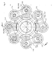
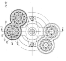
- first coupling half 10 contains a hub 14 with a flange 16.
- second coupling half 12 has a hub 18 and a flange facing the flange 16 2 0 .
- intermediate link 22 is an elongated part which extends (in the rest position when the waves are aligned) perpendicular to the axis of rotation 26 and has a crank 28 in the middle.
- the intermediate member 24 is also an elongated part which extends crossed to the intermediate member 22 perpendicular to the axis of rotation 26 and has a crank 3o opposite to the crank 28 in the middle.
- the intermediate members 22 and 24 engage with the cranks 28 and 30, respectively, so that their ends, for example 32 and 34, lie in a common plane.
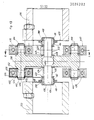
- pins 36 and 38 lie behind the paper plane of FIG. 2, which is represented by line A-B in FIG. 1. Two other pins are symmetrical to pins 36 and 38 in front of the paper plane. The arrangement is practically the same as that shown in FIG. 1 for the second coupling half 12.
- the flange 20 of the second coupling half 12 carries four pins 40, 42, 44, 46 (FIG. 1), of which the pins 42 and 46 are visible in FIG. 2.
- the two further pins of the first coupling half 10 are aligned with the pins 40 and 44.
- Each of the pins 36, 38, the two further pins (not visible) and the pin 40, 42, 44, 46 has a spherical bead 48.
- the intermediate links 22 and 24 there are pairs of aligned pins on both sides. 2, the pair of pins 50, 52 at the end 32 of the intermediate link 22 and the pair 54, 56 at the end 34 of the intermediate link 24 are visible.
- the pairs of aligned pins 58, 60 and 62, 64 are seated in the same way, it being assumed that the pins 58 and 62 are directed towards the first coupling half 10.
- the pins 50, 52, 54, 56, 58, 60, 62 and 64 each have a spherical bead 66 at their ends, which lies in the same radial plane as the spherical bead 48 on the pin of the adjacent coupling half.
- the intermediate link 22 is connected to the first coupling half 10 by a link arrangement of two diametrically opposed, movably articulated links, namely the link 68 (FIG. 2) and one that is not visible in FIG. 2 and is aligned with the link 70 in FIG. 1 Handlebar connected.
- the diametrically opposite links extend from the intermediate member 22 in the same direction, namely counterclockwise, in the circumferential direction.
- the intermediate member 22 is also connected to the second coupling half 12 via a second link arrangement of two diametrically opposite links 70 and 72 articulated on all sides. Viewed in the axial direction, one link of the one pair is aligned with one link of the other pair, ie, for example, the link 68 is aligned with the link 72.
- the second link 24 with the first coupling half 10 is diametrically opposed to one another via a link arrangement Handlebars, namely the handlebar 74 in FIG. 2 and a handlebar not visible in the figures and aligned with the handlebar 76 of FIG. 1.
- the second intermediate link 24 is connected to the second coupling half 12 via a second link arrangement, which consists of the diametrically opposed links 76 and 78 articulated on all sides.
- the diametrically opposite links extend from the intermediate member 24 in the same direction of rotation, namely clockwise, in the circumferential direction.
- one link of one pair is aligned with one link of the other pair, that is, for example, link 74 with link 78, as seen in the axial direction.
- the two intermediate members 22 and 24 are rotatably connected to one another by a bolt 80 about a central axis, which coincides with the rotational axis 26 in the rest position shown.
- the links 68, 70, 72, 74, 76, 78, etc. are each connected to the coupling halves 10, 12 and the intermediate members 22, 24 so as to be movable on all sides via rubber pads.
- the type of connection is described below with reference to the handlebar 72.
- the other handlebars are designed in the same way.
- the link 72 has a spectacle-shaped housing 84 which forms two cylindrical chambers 82 and 84.
- the housing 84 forms on one side radially inwardly projecting edges 86, 88 which delimit the otherwise continuous chambers 82 and 84 while leaving openings 90 and 9-2 open.
- the pin 52 of the intermediate member 22 projects through the opening 92 into the chamber 84, so that the spherical bead 66 is seated centrally in the chamber 84.
- the pin 42 of the second coupling half 12 projects into the chamber 82, so that the spherical bead 48 of the pin. 42 sits centrally in the chamber 82 and in the same radial plane as the bead 66 of the pin 52.
- a rubber dome 94 sits in the chamber 82 in the annular space between the wall of the chamber 82 and the spherical Bead 48. It is pressed into this annular space and lies on one side against the edge 86, while on the other side it is held by a ring 96 which is secured by a snap ring 98. Similarly, a rubber dome 100 is provided in the chamber 84 in the annulus between the wall of the chamber 84 and the spherical bead 66.
- the link 72 is articulated on the coupling half 12 and the intermediate member 22 in an elastic and movable manner.
- the pin 80 prevents instability, which could occur due to the centrifugal force when the shaft coupling is not loaded when an intermediate member 22 or 24 moves out of its central position.
- FIG. 2 represents a "snapshot" and the handlebar pairs 68, 72 and 74, 78 interchange their functions after a 180 turn. It should also be noted that the links do not extend radially, as can be seen from FIG. 1.
- the link 68 pivoted counterclockwise experiences this same apparent shortening, which is compensated in the same way by the pivoting movement of the intermediate member 22.
- the pin 50 approaches the pin 36 in the circumferential direction.
- the angular position of the pins 36 and 42 relative to one another remains unchanged.
- the compensation takes place at the opposite end of the intermediate link 22.
- the link 70 is pivoted clockwise and the link axially aligned therewith, which is articulated on the first coupling half 10, counter-clockwise, namely by the same angles as the links 68 and 72
- the intermediate member 22 is rotated counterclockwise and, for example, the pin 60 of the intermediate member approaches the pin 44 of the second coupling half 12 in the circumferential direction.
- the mutual angular position of the pins provided on the two coupling halves 10, 12 remains unchanged.
- the handlebars e.g. 70 and 72 are hinged to the intermediate member 22 so that they both extend from this intermediate member counterclockwise approximately in the circumferential direction. All links, e.g. 76 and 78, articulated so that they extend from this intermediate member 24 in the clockwise direction of Fig. 1 approximately in the circumferential direction.
- the coupling also allows one with homokinetic transmission of the rotary movement Radial misalignment of the waves.
- the coupling thus allows the rotational movement to be transmitted in an angular or homokinetic manner even in the event of a radial offset.
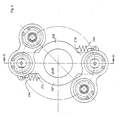
- a first coupling half is designated by 104 and a second coupling half by 106. Between the two coupling halves a first intermediate member 108 and a second intermediate member 110 are arranged.
- the first coupling half 104 contains a hub 112 with four radial arms, which are each angularly offset from one another by 90 ° and of which only the arm 114 is visible in the section of FIG. 4.
- the second coupling half 106 contains a hub 116 with four radial arms 118, 120, 122 and 124, which can be seen in FIG. 3 and of which only the arm 118 is visible in the section of FIG. 4.
- the intermediate links 108 and 110 contain rings 126 and 128, respectively.
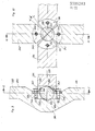
- the ring 126 has a bearing boss 130 on one side and a similar bearing boss 132 on the diametrically opposite side, only the bearing boss 130 being visible in section EF of FIG. 3 is.
- the ring 128 has a bearing boss 134 on one side and a similar bearing boss 136 on the diametrically opposite side.
- the bearing lugs 134 and 136 which are not visible in the section of FIG. 4, are constructed in the same way as the bearing lug 130 to be described.
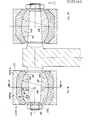
- the arm 114 ends in a cylindrical housing 138 which is open at both ends.
- the housing 138 forms an inwardly projecting edge 140.
- An axis or a pin 142 with a bead 144 in the middle sits centrally in the housing 138.
- a Gummikalotte 146 is arranged in the annular space between the inner wall of the housing 1 '38, and the axis 142 .
- the rubber dome 146 is pressed into the annular space until it comes to rest on the edge 140.
- the rubber dome 146 is replaced by a ring 148 inserted into the housing 138 held, which is secured by a snap ring 150. In this way, the axle 142 is mounted in the housing 138 in an elastic and movable manner.
- the ends of the axles 142 protrude from the housing 138 on both sides.
- Each of the ends has a flattened section 152, 154 with opposing flat surfaces and a threaded section 156, 158.
- the openings 163 form straight edges which rest on the flat surfaces, as a result of which the links are non-rotatably connected to the axles 142.
- Each of the arms 114 and 118, 120, 122, 124 of the coupling halves 104, 106 carries a bearing arrangement constructed in this way, which is generally designated by 168 in FIG. 4.
- 4 shows the bearing arrangement 168 of the coupling half 104.
- 3 shows the bearing arrangements 170, 172, 174 and 176, which are seated on the arms 118, 120, 122 and 124, respectively.
- the arms and bearing arrangements on the first coupling half 104 are, seen in the axial direction S, aligned behind the arms 118, 120, 122, 124 and bearing arrangements 170, 172, 174, 176.
- the bearing lugs 130 and 132 of the first intermediate member 108 contain arms 178, 180 extending in the axial direction on both sides of the ring 126.
- the axial arms ' 178, 180 carry on their Ends a bearing assembly 1.82 and 184, respectively to A rt of the bearing assembly 168.
- the lengths of the arms 178 and 180 are selected such that the bearing assemblies 182 and 184 of the bearing lugs 130,132 and 134 ', 136 of the links 108 and 110, the same in the Layers and on the same pitch circles as the bearing arrangements 168 and others 170, 172, 174, 176 of the first and second coupling halves 104 and 106, respectively.
- the right-hand bearing arrangements in Fig. 4, e.g. 184, the bearing lugs 130, 132, 134, 136 of the intermediate links 108, 110 are connected to the adjacent bearing arrangements 172, 176, 170 and 174 via pairs of link-like links 186, 188, and 190, 192 and 194, 196 and 198, 200, respectively.
- the intermediate links 108, 110 are rotatably supported in the area of the bearing lugs 130, 132 and 134, 136 via arcuate sliding surfaces 202, 204 and 206, 208 on the ring 128 and 126 of the other intermediate link 110 and 108, respectively.
- the mode of operation of the arrangement described is in principle the same as in the embodiment according to FIGS. 1 and 2.
- the embodiment according to FIGS. 3 and 4 is particularly suitable for shaft couplings which have to work at high speeds.
- the handlebars form the housing for the storage.
- This housing is mounted on pins which protrude from one side of the coupling half or the intermediate link. This gives the handlebars a relatively large mass, so that high centrifugal forces are effective at high speeds. These high centrifugal forces act on the pins on one side.
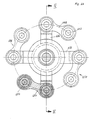
- the intermediate link 210 forms a ring 212 with diametrically opposite, radially outwardly projecting arms 214 and 216.
- the arm 214 carries a pair of aligned, axial pins 218, 220 on opposite sides with beads 222 and 224.
- the beads 222, 224 are each made of a rubber dome Surround 226,228, which sits in a cylindrical recess 230,232 each of a link 234 or 236.
- the rubber cups 226 and 228 are each in two parts and placed around the beads 222 and 224. The ends of the rubber pads, e.g.
- the rubber dome 226, are covered by essentially conical sheet metal parts 238, 240 with angled edges 242 and 244, the edge 242 in each case forming a radial flange and the edge 244 forming an axial collar.
- the sheet metal part 240 rests with the edge 242 on a radially inwardly projecting edge 246 of the link 234.
- the edge 242 of the sheet metal part 238 is held by a ring 248 inserted into the recess 230, which is secured by a snap ring 250.
- the links 234 and 236 are elastically articulated on pins 252 and 254 of the first and second coupling halves (not shown).
- pins 216 and 258 are attached to the arm 216, to which links 260 and 262 are articulated in the same manner as described above. These links 260, 262 are articulated in a manner not shown, similar to links 234 and 236, to the first and second coupling halves, respectively.
- the intermediate member 210 may be elastically tied to the central position. This is indicated in Fig. 5 by the springs 264 and 266.
- the intermediate member 210 is formed with the ring 212 and the central opening 268 so that a shaft can extend through it.
- the intermediate links can also be designed as rings which are mounted on or on top of one another and which allow the passage of a central axis or shaft.
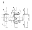
- 270 designates a first coupling half and 272 designates a second coupling half.
- the coupling halves each of which is supported by a hub 274 or 276 and four radial lugs, e.g. 278 and 280 are formed, two mutually crossed intermediate members 282 and 284 are arranged.
- the first coupling half 270 is connected via a first link arrangement to a pair of diametrically opposed links 286, 288 via the dome pins 287, 289 and 291, 293 to the intermediate link 282.
- the second coupling half is 272
- the intermediate link 282 also connected to the intermediate link 282 via a second link arrangement with a pair of diametrically opposed links 290, 292.
- One handlebar each, e.g. 286 of one pair is aligned with an arm 290 of the other pair when viewed in the axial direction.
- the handlebar 282 is aligned with the handlebar 292 when viewed in the axial direction.
- the diametrically opposed links 286, 290 and 288, 292 each extend from the intermediate member in the same direction of rotation essentially in the circumferential direction.
- the intermediate member 284 is connected to the first coupling half 270 and the second coupling half 272.
- a link 294 at the right end of the link 284 in FIG. 7 connects it to the first coupling half and a link 296 aligned therewith connects the link 284 to the second coupling half 272.
- Another pair of aligned links between the link 284 and the first or The second coupling half 270 and 272 is provided on the left end in FIG. 7, which are not visible in FIG. 8 and of which a link 298 is shown in FIG.
- the links 294, 296 and 298 also extend from the intermediate member 284 in the same direction of rotation, essentially in the circumferential direction.
- the links extend from the one link 22 counterclockwise and from the link 24 clockwise approximately in the circumferential direction
- the links extend from all links in the same direction, namely clockwise in FIG. 7.
- the two intermediate members 22 and 24 are rotatably connected to one another by a bolt 80 about a central axis, which coincides with the rotational axis in the rest position, in the present embodiment, the intermediate members 282 and 284 are movable on all sides Joint 300 connected together.
- each of the two intersecting intermediate members 282 and 284 has a pair of sector-shaped projections 310, 312 and 314, 316, which are angularly offset from one another by 180 ° and centered on the axis of rotation 308 and which each extend over an angle of extend less than 90 °, for example 80 °.
- a spherical depression 302 and 304 is provided, centered on the axis of rotation 308, so that spherical bearing surfaces of sector-shaped basic shape are formed on the projections.
- the projections 310,312 of the one intermediate member 282 engage between the projections 314,316, the bearing ball 306 being held between the pairs of bearing surfaces. Since the projections each extend over an angle of, for example, 80 °, an angular range of approximately 10 ° is free between the interlocking projections, which allows the intermediate members to be rotated about the circumferential axis 308.
- the intermediate members 282 and 284 are held by the bearing ball 306 with their mutually facing surfaces at a distance from one another, so that around the bearing ball also a pivoting movement of the intermediate members 282 and 284 to one another and from their radial planes can be done as it is necessary to compensate for a radial offset. In the radial direction, however, the intermediate links are centered with respect to one another, so that none of the intermediate links can be pulled radially outward by centrifugal forces.
- the intermediate members are formed by elongated radial bodies with a central offset 318 or 320 and extending on both sides of the same, radial arms 322, 324 and 326, 328 carrying the links.
- the intersecting links 282, 284 engage with one another with their crankings 318, 320 such that the radial arms 322, 324, 326 and 328 lie essentially in a common plane.
- the intermediate members 282 and 284 can have transverse depressions 330 and 332 on the sides facing one another in the region of the cranks 318, 320.
- the projections 310, 312 and 314, 316 extend in the longitudinal direction of the intermediate members 282 and 284 into these depressions 330 and 332, respectively.
- prestressed, elastic tension members 334, 336 are provided between the intermediate members 282 and 284, which are only indicated schematically in FIG. 8, so that the intermediate members 282 and 284 are held non-positively in contact with the bearing ball 306.
- FIGS. 9 and 10 A modified version is shown in FIGS. 9 and 10.
- the construction of the embodiment according to FIGS. 9 and 10 is similar to the embodiment according to FIGS. 7 and 8, and corresponding parts are provided with the same reference numerals as there.
- each intermediate link for example 282 lies on both sides of the depression 330 in the equatorial plane of the bearing ball 306.
- retaining links 340, 342 are screwed 344, 346 with screws 344, 346 (see FIG. 7 ) attached.
- These holding members 340, 342 have spherical contact surfaces 348, 350.
- the holding members 340, 342 extend over the bearing ball 306 and bear against the bearing surfaces 348, 350 thereon.
- the intermediate member 284 engages with holding members (not visible in FIGS. 9 and 10) around the left half of the bearing ball 306 in FIG. 9.
- the projections 314 and 316 and the cut screws 352,354 shown to attach these latter holding members can be seen.
- both intermediate members are positively connected to the bearing ball 306 by the bearing and contact surfaces 302, 304 and 348, 350.
- 11 shows another embodiment of the joint 360 which is provided between the intermediate members 356, 358 and is movable on all sides.
- the intermediate pieces 356, 358 are formed by elongated straight bodies.
- One of the intermediate pieces, namely the intermediate piece, 356, has a spherical bead 362 in the middle.
- the other intermediate piece has a cylindrical opening 364 in the middle, into which the bead 362 of one intermediate piece 356 is inserted.
- Both sides of the bead 362 are 364,368 with spherical bearing surfaces inserted into the opening 364 and secured by spacer rings 370,372 and snap rings 374,376, so that the bead 362 is positively held in the opening 364.
- the intermediate piece 358 consists of a ring 378 which forms the opening 364 and radial arms which adjoin both sides of this ring and which hold the bearing pins, e.g. Wear 380.
- the journals 382.384 and 386.388 may not be made in one piece with the intermediate piece 356 in this arrangement, otherwise the adapter 356 could not be e Disclosure through the opening 364 through g.
- the intermediate piece 356 therefore has transverse bores at its ends, through which a continuous pin forming the Laherzap 382, 384 or 386, 388 is inserted. The parts of the joints are then placed on these journals 382, 384, which in turn have to be straight, cylindrical journals for insertion.
- the two intermediate links 356 and 358 which are arranged perpendicular to one another in the idle state, are connected to one another in the middle by a joint which can be moved on all sides and are thus centered on one another.
- a bushing 396, 398 with a spherical outer surface and a cylindrical bearing bore is mounted in a spherical bearing surface 400 or 402 on the two coupling halves.
- a pin 404 is rotatably and axially movable, the in the middle carries a spherical bead 406.
- the only intermediate member 390 is supported on this bead with an axial bore 408.
- the spherical bearing surface 400 or 402 is formed in each case by two bearing half-shells 410, 412 or 414, 416, which enclose the bushing 396 or 398. These half-shells are fastened centrally by webs 418, 420 to the coupling halves 392 and 394 designed as hubs.
- Pairs of washers 422, 424 and 426, 428 are guided on both ends of the pin 404, one washer 422 and 428, respectively, of each pair on a part of the adjacent coupling half 392 and 394, namely the bearing half-shell 412 and 414, and the other washer 424.426 abuts the intermediate member 390 around the axial bore 408.
- Compression springs 430 and 432 are provided between the washers 422, 424 and 426, 428 of each pair, which surround the respective ends of the pin 404.
- the bearing ball 406 moves by half the shaft offset.
- the change in the distance between the centers of curvature of the spherical bearing surfaces 400 and 402 caused by the shaft offset is compensated for when the pin 404 is inclined by axially displacing the pin ends in the bushes 396, 398.
- Joints are provided for articulating the links 434, 436, 338 and 440 to the pins 442, 444, 446 and 448 of the intermediate member 390.
- These consist of one on the journal, e.g. 442, seated roller bearing 450, which ensures free rotation about the journal axis, an inner ring 452 supported on the roller bearing with a spherical outer surface 454, in which longitudinal arcuate grooves 456 (FIG.
- the handlebars can, however, also be articulated elastically on the pins of the intermediate links via rubber pads. In the embodiment according to FIGS. 7 and 8, this is done in the same way as in FIG. 2 is shown.
- the "rubber pads" used there which are known per se (DE-OS 25 20 947, in particular Fig. 16 or DE-Gbm 71 33 899) are not very flexible. This is because when the joint is deflected, the A large part of the rubber-elastic mass is pressed against rigid parts of the joint and thus subjected to compression.
- the bead can be made spherical with a center at the kink point of the joint. Then, however, the bead becomes relatively thick, so that either the dimensions of the entire joint become undesirably large or the space available for the rubber-elastic mass is reduced.
- the invention is based on the further object of creating an elastic joint ("rubber dome") which, with the same dimensions, has greater flexibility compared to the previously known joints mentioned.
- an elastic joint suitable for the embodiment according to FIG. 11 is to be created.
- the hinge contains one on the pin, e.g. 382 of the intermediate member 356 seated bead 468 formed as a separate component (FIG. 14, an eye 470 of the handlebar surrounding the bead 468 at a distance and a rubber-elastic mass 472 filling the space between bead 468 and eye 470.
- the outer surface of the bead 468 is in each longitudinal plane substantially about a point beyond the axis 474 of the pin 382, e.g. 476 curved.
- the pin 382 or 384 is in each case weakly conical, and the bead 468 has a correspondingly conical opening with which the bead on the pin 382 or 384 is postponed.
- the bead is 468 secured by means of an annular washer 478 and a nut 480 screwed onto the end of the pin 382.
- the inner surface of the eye 470 is also preferably curved in each longitudinal plane essentially around a point lying beyond the axis of the pin 382.
- the outer surface 482 of the bead 468 is curved around a point 484 lying approximately on the lateral surface of the pin 384.
- the generating de outer surface 482 is therefore a circle curved around this point 484.
- the outer surface 486 of the bead 468 is curved around a point 488 lying approximately on the opposite side of the outer surface 486.
- the generating surface 486 is a circle that is curved here around point 488.
- the curvature of the outer surface of the bead can also result from a sequence of adjoining conical ring surfaces with different cone angles.
- Such embodiments are shown in Figs. 14 and represented 1 6, wherein the resulting "mean curvature" in the case of the embodiment of Fig. 14 as that of the embodiment of FIG. ZS and in the case of the embodiment of Fig. 16 as that of the embodiment according to Fig. 17 corresponds.
- the generating one of the outer surface of the bead 468 is a polygon, the sides of which correspond in each case to a central angle of 15 ° with respect to a central point lying on the axis 474 of the pin 382, with neighboring ones Include an angle of 15 ° on each side of the polygon.
- the resulting center of curvature 476 lies on the opposite lateral surface of the pin 382.
- the generating surface 486 of the bead 468 is also a polygon.
- the sides of this polygon correspond symmetrically to the central plane center angle around the center point 488 of 15 °, 30 ° and again 15 °. This results in a central center of curvature 492, which is also on the opposite side of the outer surface 486, similar to the embodiment according to FIG. 17
- the bead 468 consists of two halves 468a and 468b, the half 468a being displaceable against the half 468b by the washer 478 and the nut 480 in the position shown in FIG. 16.
- the handlebar 469 shown in Fig. 16 also consists of two halves 469a and 469b, the rubber-elastic mass 472 in both halves 469a, 469b of the handlebar 469 with the associated bead halves 468a, 468b being vulcanized in such a way that when the handlebar halves 469a, 469b are pulled together a preload is generated in the rubber-elastic mass 472 by the screws 471.
- a total of six screws 471 are provided, as shown in FIG. 18.
- the bead is in two parts and consists of two axially against one another closing parts 494 and 496. Means are provided for axially moving these two parts 494, 496 apart for the purpose of prestressing the rubber-elastic mass 498.
- the two parts 494 and 496 form a bead with an outer surface 500 in the initial state, the generatrix of which is curved around a point 502 lying on the lateral surface of the pin 382.
- the bead is surrounded at a distance by an eye 504 of the handlebar, which has a spherical inner surface 506. This inner surface 506 is curved around a central point 508 lying on the axis of the pin 382.
- a sleeve 510 is rotatably mounted on the pin 382, which has a right-hand thread on one side and a left-hand thread 512 or 514 on the other half.
- the two parts 494 and 496 of the bead are screwed onto the right-hand and left-hand threads 512 and 514, respectively, with corresponding threads.
- an annular disk 514 is provided which extends from the inside and is held between the parts 494 and 496.
- Sleeve 510, bead 494, 496 and eye 504 are cast with the rubber-elastic mass 498 in the initial state, as indicated in the upper part of FIG. 19.
- the sleeve 510 sits on a gravel mold core 518, which contains a channel 520 for the supply of rubber-elastic mass.
- the eye 504 sits on the one hand on the gravel mold core 518 and on the other hand on a sleeve-shaped end piece 522, which likewise contains a channel 524 for the supply of rubber-elastic mass. In this way, a closed annular space is formed between the eye 504 and the bead 594,496, into which the annular disc 514 protrudes.
- the closure piece 522 can then be removed and the component consisting of the sleeve 510, the bead 494, 496, the rubber-elastic mass 498 and the eye 504 can be removed from the gravel mold core 518. This component is then placed on the pin 382 and secured by the washer 526 and nut 528. If the elastic mass 498 is to be preloaded, the sleeve 510 is rotated beforehand. The two parts 494 and 496 of the bead are screwed apart, as shown in the lower part of FIG. 13, and the rubber-elastic mass 498 is prestressed against the inner surface 506.
- the purpose of the annular disc 514 is to ensure defined conditions in the region of the parting line between the parts 494 and 496 and to prevent the rubber mass from tearing when the parts 494 and 496 are pulled apart.
- a sleeve 530 provided with an external thread is rotatably mounted on the pin 384 as a means for moving the parts apart.
- One of the parts 532 of the bead consisting of two parts 532 and 534 sits on this sleeve with an internal thread.
- rotating the sleeve one part is then moved axially relative to the other part, which likewise prestresses the rubber-elastic mass 536.
- the inner surface like the inner surface 506 by a circle, can be defined as generating.
- the generatrix of the inner surface can also, as shown for example in FIGS. 8 to 11 and 14 Be a polygon.
- the inner surface can be formed by a central cylindrical surface and adjoining conical surfaces.
- FIG. 21 shows a bearing ball 540 which is held between two intermediate links 542 and 544, which are arranged in a crossed manner, in a shaft coupling of the type shown in FIGS. 1 to 4 of German patent application P 30 16 267.5 of April 24, 1980.
- Each of the intermediate links 542 and 544 is via (not shown) handlebar arrangements of the type explained above connected to the two coupling halves.
- the intermediate members 542 and 544 are arranged at 90 ° to one another at an angular offset from one another about the rotational axis 546.
- the intermediate members 542 and 544 have mutually facing and aligned depressions 548, 550 between which the bearing ball 540 is held.
- the bearing ball 540 is provided with friction-reducing agents. Although the bearing ball 540 is not used for the transmission of the torque in the present shaft coupling, e.g. radial forces act on the bearing ball due to centrifugal forces. In addition, the intermediate members 542 and 544 make their compensatory movements to each other and to the bearing ball 540 when there is a shaft misalignment.
- the friction-reducing agents are intended to prevent wear of the bearing ball during the compensating movements and simultaneous action of the radial force.
- the friction-reducing agents have a friction-reducing coating 552 on the surface of the depressions 548,550.
- This covering 552 can be formed, for example, by a self-lubricating bearing material.
- the bearing ball 540 is designed as a hollow ball and is filled with a lubricant, preferably grease.
- the bearing ball 540 is made from two hemispherical shells 554 and 556, which are welded together.
- the interior 558 of the bearing ball 540 is connected via radial channels 560 to the surface parts held in the recesses 548,550.
- Ring grooves 562 are formed on the surface of the bearing ball 540 and are connected to the interior 558 of the bearing ball 540 through the radial channels 560.
- annular grooves 564 are formed, which are connected to the ring grooves 562 on the outer surface of the bearing ball and into each of which a lubricant channel 566 provided in the intermediate member 542 or 544 opens.
- Lubricants e.g. Lubricating grease, via the lubricant channel 566, the annular groove 564, the annular groove 562 and the radial channels 560 are pressed into the interior 558 of the bearing ball 540.
- the depressions 548, 550 can be made slightly shallower than the diameter of the bearing ball 540.
- rubber joints on the handlebars are pretensioned in such a way that the intermediate members 542, 544 are pressed elastically against the bearing ball 540 and remain in contact with the bearing ball 540 in the event of any wear.
- Elastic tension members 571, 573 can also be provided between the intermediate members.
- FIG. 22 shows a shaft coupling which corresponds in the basic structure to the embodiment according to FIGS. 5 and &.
- Only a single intermediate member 572 is provided there, which has two arms 574 and 576.
- the arm 574 carries a continuous axial pin 577 which is provided with threads 578,580 at its ends.
- the ends 582 and 584 of the pin 577 protruding from the arm 574 on both sides are surrounded by sleeves 586 and 588, respectively, which are tightened against the end faces of the arm 574 by nuts 590 and 592, which are screwed onto the threads 578, 580.
- the sleeves 586 and 588 have beads 594 and 596, respectively.
- the beads 594 and 596 are each surrounded by a rubber dome 598 and 600, respectively, which is seated in a recess 602 and 604, each of a link 606 and 608, respectively.
- the links 606 and 608 extend parallel to one another in the idle state and are connected at their other ends in a similar manner to pins 610 and 612, respectively, to the first and second (not shown) Coupling halves are seated.
- the arm 576 is connected via links 614 and 616, which are antiparallel to the links 606 and 608 in the idle state, with pins (not shown) of the coupling halves.
- the intermediate member 572 is mounted on a tube 620 via a ball joint 618.
- the tube 620 is connected at both ends to the first and second coupling halves via articulated connections which are movable on all sides (not shown).
- the articulated connections can be designed, for example, in the manner of FIG. 7 of patent application P 30 16 267.5 of April 26, 1980.
- a continuous shaft 622 is passed centrally through the tube.
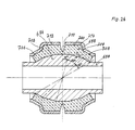
- FIG. 23 and 24 show a shaft coupling with two intermediate links 634 and 636, which are arranged crossed to one another and centered on one another by a bearing ball 638.
- the link 634 is over a pair of diametrically opposed, in the rest position anti-parallel mutually articulated links 640,642 with pins 644,646 of the first coupling half (not shown) and via a second pair of links 648,650, which in the rest position are aligned with the links 640 and 642 in the axial direction, connected with pins 652 and 654 of the second coupling half.
- intermediate link 636 is connected on the one hand to the first coupling half and on the other hand to the second coupling half via two pairs 656, 658 of links aligned in the axial direction.
- the design of each individual link 634, 636 and the design and articulation of the handlebars essentially correspond to the arrangement in FIG. 22 and are therefore not described again in detail.
- the design of the bearing ball 638 and provided thereon friction-reducing agent is similar to that of F ig.21.
- Such a bearing ball from FIG. 1 could also be used in connection with the intermediate members 634 and 536 from FIG. 24.
- the bearing ball 638 has a central opening 660 with a welded-in pipe section 662.
- a continuous wave 664: L is passed through the central opening 660.
- Fig. 25 shows an embodiment of the rubber cups, by means of which the links on pins of the intermediate link, e.g. 572 in Fig. 22 are articulated.
- the rubber caps each contain a bead 668 seated on the pin 666, an eye 670 of the handlebar surrounding the bead 668 at a distance and a rubber-elastic mass 672 filling the space between the bead 668 and eye 670.
- the formation of the bead 668 corresponds approximately to FIG. 10 the patent application P 30 16 267.5, ie the generatrix of the outer surface bead 668 is a polygon.
- the sides of this polygon, as indicated in Fig. 25, correspond symmetrically to the center plane center angles around the center 674 of 15 °, 30 and again 15 °. This results in a center of curvature that lies on the opposite side of the outer surface of the G68 bead.
- the rubber-elastic mass is prestressed in each case by annular pressure members 676, 678 arranged on both sides around the pin 666, which are pressed inward in the eye 670 under prestress of the rubber compound 672 and are secured in the prestressing position.
- the annular pressure members 676,678 are each sheet metal parts with an axially outwardly tapering conical inner part G80 and a radially outwardly projecting flange 682 which adjoins the further end.
- the radially outwardly projecting flanges 682 of the pressure members 676,678 lie in the eye 670 of spacers 684,686 inserted on both sides.
- the spacer rings 684,686 are held by snap rings 688,690 which snap into grooves on the inner surface of the eye.
- Fig. 26 shows another embodiment of a rubber joint.
- a sleeve 694 with a bead 696 is seated on a pin.
- the sleeve 694 can be clamped onto the pin in the manner of FIG. 22.
- the bead 696 has the same shape as the bead 668 of FIG. 25.
- a rubber-elastic mass 698 sits on the bead 696.
- the outer surface of the rubber-elastic mass 698 has a cylindrical middle part 700, radial ring shoulders 702, 704 adjoining it on both sides and conical surfaces 706, 708 tapering towards the ends.
- the rubber-elastic mass 698 has on the cylindrical middle part 700 of its outer surface in the middle a cross-sectionally V-shaped groove 710.
- sheet metal parts 712, 714 of shape adapted to the shape of the lateral surface are placed on the lateral surface.
- the circumferential groove 710 allows the rubber-elastic mass 698 to evade when this rubber joint moves forward.
Landscapes
- Engineering & Computer Science (AREA)
- General Engineering & Computer Science (AREA)
- Mechanical Engineering (AREA)
- Pivots And Pivotal Connections (AREA)
- Transmission Devices (AREA)
- Steering Devices For Bicycles And Motorcycles (AREA)
- Mechanical Operated Clutches (AREA)
Applications Claiming Priority (6)
| Application Number | Priority Date | Filing Date | Title |
|---|---|---|---|
| DE3007348 | 1980-02-27 | ||
| DE19803007348 DE3007348A1 (de) | 1980-02-27 | 1980-02-27 | Wellenkupplung |
| DE19803016267 DE3016267A1 (de) | 1980-04-26 | 1980-04-26 | Wellenkupplung |
| DE3016267 | 1980-04-26 | ||
| DE19803032373 DE3032373A1 (de) | 1980-08-28 | 1980-08-28 | Wellenkupplung |
| DE3032373 | 1980-08-28 |
Publications (2)
| Publication Number | Publication Date |
|---|---|
| EP0035283A1 true EP0035283A1 (fr) | 1981-09-09 |
| EP0035283B1 EP0035283B1 (fr) | 1985-05-15 |
Family
ID=27188504
Family Applications (2)
| Application Number | Title | Priority Date | Filing Date |
|---|---|---|---|
| EP81900523A Pending EP0046778A1 (fr) | 1980-02-27 | 1981-02-25 | Accouplement homocinetique |
| EP81102035A Expired EP0035283B1 (fr) | 1980-02-27 | 1981-02-25 | Accouplement d'arbres |
Family Applications Before (1)
| Application Number | Title | Priority Date | Filing Date |
|---|---|---|---|
| EP81900523A Pending EP0046778A1 (fr) | 1980-02-27 | 1981-02-25 | Accouplement homocinetique |
Country Status (8)
| Country | Link |
|---|---|
| EP (2) | EP0046778A1 (fr) |
| JP (1) | JPS57500385A (fr) |
| BR (1) | BR8107087A (fr) |
| CA (1) | CA1165577A (fr) |
| DD (1) | DD156622A5 (fr) |
| DE (1) | DE3170470D1 (fr) |
| SU (1) | SU1123554A3 (fr) |
| WO (1) | WO1981002452A1 (fr) |
Cited By (9)
| Publication number | Priority date | Publication date | Assignee | Title |
|---|---|---|---|---|
| EP0175867A1 (fr) * | 1984-09-14 | 1986-04-02 | Thyssen Industrie Ag | Accouplement double à cardan |
| WO1986007421A1 (fr) * | 1985-06-04 | 1986-12-18 | Ilie Chivari | Embrayage pour relier des elements de machines axialement decentres |
| GB2191562A (en) * | 1986-06-14 | 1987-12-16 | John Cannon Braithwaite | Shaft flexible coupling |
| WO1994005923A1 (fr) * | 1992-08-31 | 1994-03-17 | Ilie Chivari | Accouplement homocinetique |
| EP2765321A3 (fr) * | 2013-02-12 | 2014-12-10 | Centa-Antriebe Kirschey GmbH | Unité de couplage |
| WO2016097195A1 (fr) * | 2014-12-17 | 2016-06-23 | Sueddeutsche Gelenkscheibenfabrik Gmbh & Co. Kg | Dispositif d'accouplement et dispositif d'articulation renforcé de fils |
| DE102019220352A1 (de) * | 2019-12-20 | 2021-06-24 | Zf Friedrichshafen Ag | Gelenkeinrichtung zum gelenkigen Verbinden zweier Bauteile |
| WO2023151843A1 (fr) * | 2022-02-10 | 2023-08-17 | Siemens Mobility GmbH | Accouplement d'essieu |
| EP4045806B1 (fr) * | 2019-10-15 | 2025-03-26 | Hackforth GmbH | Embrayage |
Families Citing this family (5)
| Publication number | Priority date | Publication date | Assignee | Title |
|---|---|---|---|---|
| RU2108704C1 (ru) * | 1996-01-03 | 1998-04-20 | Алексей Николаевич Цепляев | Полозовидный сошник |
| WO2014172156A1 (fr) * | 2013-04-17 | 2014-10-23 | Eaton Corporation | Élément d'accouplement pour compresseur à suralimentation |
| USD866603S1 (en) | 2016-08-17 | 2019-11-12 | Eaton Corporation | Elastomer series coupling damper for supercharger |
| CN112670135B (zh) * | 2020-11-26 | 2022-08-19 | 国家电网有限公司 | 一种联轴器和断路器 |
| CN116857231B (zh) * | 2023-07-13 | 2024-10-01 | 江苏航天水力设备有限公司 | 一种前置灯泡式贯流泵 |
Citations (7)
| Publication number | Priority date | Publication date | Assignee | Title |
|---|---|---|---|---|
| FR856273A (fr) * | 1939-02-20 | 1940-06-10 | Perfectionnements aux accouplements et aux transmissions | |
| FR1427840A (fr) * | 1964-12-17 | 1966-02-11 | Alsthom Cgee | Accouplement élastique |
| FR1486346A (fr) * | 1966-07-11 | 1967-06-23 | Accouplement élastique | |
| DE2520947A1 (de) * | 1974-05-28 | 1975-12-18 | Raoul Dipl Ing Joern | Elastisches gelenklager |
| US4033144A (en) * | 1976-02-18 | 1977-07-05 | Allen Clifford H | Flexible coupling |
| DE2741603A1 (de) * | 1976-09-16 | 1978-03-23 | Zeller Corp | Universalgelenk fuer gelenkwellen |
| US4187699A (en) * | 1976-10-29 | 1980-02-12 | The Zeller Corporation | Universal joint for connecting shafts |
-
1981
- 1981-02-25 DE DE8181102035T patent/DE3170470D1/de not_active Expired
- 1981-02-25 JP JP56500718A patent/JPS57500385A/ja active Pending
- 1981-02-25 BR BR8107087A patent/BR8107087A/pt unknown
- 1981-02-25 EP EP81900523A patent/EP0046778A1/fr active Pending
- 1981-02-25 WO PCT/DE1981/000037 patent/WO1981002452A1/fr not_active Ceased
- 1981-02-25 EP EP81102035A patent/EP0035283B1/fr not_active Expired
- 1981-02-26 SU SU813248902A patent/SU1123554A3/ru active
- 1981-02-26 CA CA000371769A patent/CA1165577A/fr not_active Expired
- 1981-02-27 DD DD81227947A patent/DD156622A5/de unknown
Patent Citations (7)
| Publication number | Priority date | Publication date | Assignee | Title |
|---|---|---|---|---|
| FR856273A (fr) * | 1939-02-20 | 1940-06-10 | Perfectionnements aux accouplements et aux transmissions | |
| FR1427840A (fr) * | 1964-12-17 | 1966-02-11 | Alsthom Cgee | Accouplement élastique |
| FR1486346A (fr) * | 1966-07-11 | 1967-06-23 | Accouplement élastique | |
| DE2520947A1 (de) * | 1974-05-28 | 1975-12-18 | Raoul Dipl Ing Joern | Elastisches gelenklager |
| US4033144A (en) * | 1976-02-18 | 1977-07-05 | Allen Clifford H | Flexible coupling |
| DE2741603A1 (de) * | 1976-09-16 | 1978-03-23 | Zeller Corp | Universalgelenk fuer gelenkwellen |
| US4187699A (en) * | 1976-10-29 | 1980-02-12 | The Zeller Corporation | Universal joint for connecting shafts |
Cited By (10)
| Publication number | Priority date | Publication date | Assignee | Title |
|---|---|---|---|---|
| EP0175867A1 (fr) * | 1984-09-14 | 1986-04-02 | Thyssen Industrie Ag | Accouplement double à cardan |
| WO1986007421A1 (fr) * | 1985-06-04 | 1986-12-18 | Ilie Chivari | Embrayage pour relier des elements de machines axialement decentres |
| GB2191562A (en) * | 1986-06-14 | 1987-12-16 | John Cannon Braithwaite | Shaft flexible coupling |
| WO1994005923A1 (fr) * | 1992-08-31 | 1994-03-17 | Ilie Chivari | Accouplement homocinetique |
| EP2765321A3 (fr) * | 2013-02-12 | 2014-12-10 | Centa-Antriebe Kirschey GmbH | Unité de couplage |
| WO2016097195A1 (fr) * | 2014-12-17 | 2016-06-23 | Sueddeutsche Gelenkscheibenfabrik Gmbh & Co. Kg | Dispositif d'accouplement et dispositif d'articulation renforcé de fils |
| US10794429B2 (en) | 2014-12-17 | 2020-10-06 | Siemens Mobility GmbH | Coupling device and fibre-reinforced articulation device |
| EP4045806B1 (fr) * | 2019-10-15 | 2025-03-26 | Hackforth GmbH | Embrayage |
| DE102019220352A1 (de) * | 2019-12-20 | 2021-06-24 | Zf Friedrichshafen Ag | Gelenkeinrichtung zum gelenkigen Verbinden zweier Bauteile |
| WO2023151843A1 (fr) * | 2022-02-10 | 2023-08-17 | Siemens Mobility GmbH | Accouplement d'essieu |
Also Published As
| Publication number | Publication date |
|---|---|
| CA1165577A (fr) | 1984-04-17 |
| EP0035283B1 (fr) | 1985-05-15 |
| EP0046778A1 (fr) | 1982-03-10 |
| DE3170470D1 (en) | 1985-06-20 |
| DD156622A5 (de) | 1982-09-08 |
| SU1123554A3 (ru) | 1984-11-07 |
| JPS57500385A (fr) | 1982-03-04 |
| BR8107087A (pt) | 1982-01-05 |
| WO1981002452A1 (fr) | 1981-09-03 |
Similar Documents
| Publication | Publication Date | Title |
|---|---|---|
| EP0035283B1 (fr) | Accouplement d'arbres | |
| DE3112543A1 (de) | Kupplung zur verbindung zweier wellen | |
| DE3007348A1 (de) | Wellenkupplung | |
| EP0175867B1 (fr) | Accouplement double à cardan | |
| DE2721098A1 (de) | Universalgelenk | |
| DE3121797A1 (de) | Lagerung fuer die mischtrommel eines betontransportfahrzeuges | |
| DE3732705A1 (de) | Wellenkupplung | |
| EP0011159A1 (fr) | Joint de transmission homocinétique | |
| DE3519895A1 (de) | Kupplung zum kuppeln achsversetzter maschinenteile | |
| DE2504950A1 (de) | Gelenkkupplung | |
| DE2933722C2 (fr) | ||
| DE4001145C2 (fr) | ||
| DE4430514C2 (de) | Gleichlaufdrehgelenk | |
| DD150498A5 (de) | Wellenkupplung | |
| EP0656999B1 (fr) | Accouplement homocinetique | |
| DE4216743C1 (de) | Kupplung | |
| DE3016267A1 (de) | Wellenkupplung | |
| DE4229251A1 (de) | Rollenkupplung | |
| DE4123201C1 (en) | Clutch with three intermediate members - has radial arms connected by circumferential links | |
| DE4313645C1 (de) | Kupplung | |
| DE4005198A1 (de) | Wellenkupplung | |
| EP0306441A2 (fr) | Accouplement d'arbres | |
| EP0086864A1 (fr) | Joint universel double | |
| DE3032373A1 (de) | Wellenkupplung | |
| DE2943921A1 (de) | Wellenkupplung |
Legal Events
| Date | Code | Title | Description |
|---|---|---|---|
| PUAI | Public reference made under article 153(3) epc to a published international application that has entered the european phase |
Free format text: ORIGINAL CODE: 0009012 |
|
| AK | Designated contracting states |
Designated state(s): CH DE FR GB IT LI SE |
|
| 17P | Request for examination filed |
Effective date: 19811016 |
|
| XX | Miscellaneous (additional remarks) |
Free format text: VERBUNDEN MIT 81900523.2 (EUROPAEISCHE ANMELDENUMMER) DURCH ENTSCHEIDUNG VOM 10.02.83. |
|
| RBV | Designated contracting states (corrected) |
Designated state(s): CH DE FR GB IT LI SE |
|
| RBV | Designated contracting states (corrected) |
Designated state(s): VE BU DE |
|
| RBV | Designated contracting states (corrected) |
Designated state(s): VE BU DE |
|
| ITF | It: translation for a ep patent filed | ||
| GRAA | (expected) grant |
Free format text: ORIGINAL CODE: 0009210 |
|
| AK | Designated contracting states |
Designated state(s): CH DE FR GB IT LI SE |
|
| XX | Miscellaneous (additional remarks) |
Free format text: VERBUNDEN MIT 81900523.2 (EUROPAEISCHE ANMELDENUMMER) DURCH ENTSCHEIDUNG VOM 10.02.83. |
|
| PG25 | Lapsed in a contracting state [announced via postgrant information from national office to epo] |
Ref country code: SE Effective date: 19850530 |
|
| REF | Corresponds to: |
Ref document number: 3170470 Country of ref document: DE Date of ref document: 19850620 |
|
| ET | Fr: translation filed | ||
| PLBI | Opposition filed |
Free format text: ORIGINAL CODE: 0009260 |
|
| PG25 | Lapsed in a contracting state [announced via postgrant information from national office to epo] |
Ref country code: LI Effective date: 19860228 Ref country code: CH Effective date: 19860228 |
|
| 26 | Opposition filed |
Opponent name: REICHARDT, PETER Effective date: 19860215 |
|
| REG | Reference to a national code |
Ref country code: CH Ref legal event code: PL |
|
| PLBM | Termination of opposition procedure: date of legal effect published |
Free format text: ORIGINAL CODE: 0009276 |
|
| STAA | Information on the status of an ep patent application or granted ep patent |
Free format text: STATUS: OPPOSITION PROCEDURE CLOSED |
|
| 27C | Opposition proceedings terminated |
Effective date: 19870323 |
|
| PG25 | Lapsed in a contracting state [announced via postgrant information from national office to epo] |
Ref country code: FR Free format text: LAPSE BECAUSE OF NON-PAYMENT OF DUE FEES Effective date: 19881028 |
|
| GBPC | Gb: european patent ceased through non-payment of renewal fee | ||
| PG25 | Lapsed in a contracting state [announced via postgrant information from national office to epo] |
Ref country code: GB Free format text: LAPSE BECAUSE OF NON-PAYMENT OF DUE FEES Effective date: 19881118 |
|
| REG | Reference to a national code |
Ref country code: FR Ref legal event code: ST |
|
| PG25 | Lapsed in a contracting state [announced via postgrant information from national office to epo] |
Ref country code: DE Effective date: 19891101 |
|
| EUG | Se: european patent has lapsed |
Ref document number: 81102035.3 Effective date: 19850513 |