EP0035497B1 - Dichtungsanordnung - Google Patents
Dichtungsanordnung Download PDFInfo
- Publication number
- EP0035497B1 EP0035497B1 EP80900591A EP80900591A EP0035497B1 EP 0035497 B1 EP0035497 B1 EP 0035497B1 EP 80900591 A EP80900591 A EP 80900591A EP 80900591 A EP80900591 A EP 80900591A EP 0035497 B1 EP0035497 B1 EP 0035497B1
- Authority
- EP
- European Patent Office
- Prior art keywords
- seal
- wall surface
- recess
- deflecting means
- wall
- Prior art date
- Legal status (The legal status is an assumption and is not a legal conclusion. Google has not performed a legal analysis and makes no representation as to the accuracy of the status listed.)
- Expired
Links
- 238000007789 sealing Methods 0.000 claims description 18
- 230000000712 assembly Effects 0.000 claims description 3
- 238000000429 assembly Methods 0.000 claims description 3
- 238000013459 approach Methods 0.000 claims description 2
- 239000011435 rock Substances 0.000 claims description 2
- 230000006835 compression Effects 0.000 abstract description 4
- 238000007906 compression Methods 0.000 abstract description 4
- 239000000725 suspension Substances 0.000 abstract description 3
- 230000004323 axial length Effects 0.000 description 2
- 238000006073 displacement reaction Methods 0.000 description 2
- 239000000314 lubricant Substances 0.000 description 2
- 230000001154 acute effect Effects 0.000 description 1
Images

Classifications
-
- B—PERFORMING OPERATIONS; TRANSPORTING
- B62—LAND VEHICLES FOR TRAVELLING OTHERWISE THAN ON RAILS
- B62D—MOTOR VEHICLES; TRAILERS
- B62D55/00—Endless track vehicles
- B62D55/08—Endless track units; Parts thereof
- B62D55/088—Endless track units; Parts thereof with means to exclude or remove foreign matter, e.g. sealing means, self-cleaning track links or sprockets, deflector plates or scrapers
- B62D55/0887—Track-articulation sealings against dust, water, mud or the like
-
- F—MECHANICAL ENGINEERING; LIGHTING; HEATING; WEAPONS; BLASTING
- F16—ENGINEERING ELEMENTS AND UNITS; GENERAL MEASURES FOR PRODUCING AND MAINTAINING EFFECTIVE FUNCTIONING OF MACHINES OR INSTALLATIONS; THERMAL INSULATION IN GENERAL
- F16J—PISTONS; CYLINDERS; SEALINGS
- F16J15/00—Sealings
- F16J15/16—Sealings between relatively-moving surfaces
- F16J15/34—Sealings between relatively-moving surfaces with slip-ring pressed against a more or less radial face on one member
- F16J15/3436—Pressing means
-
- F—MECHANICAL ENGINEERING; LIGHTING; HEATING; WEAPONS; BLASTING
- F16—ENGINEERING ELEMENTS AND UNITS; GENERAL MEASURES FOR PRODUCING AND MAINTAINING EFFECTIVE FUNCTIONING OF MACHINES OR INSTALLATIONS; THERMAL INSULATION IN GENERAL
- F16J—PISTONS; CYLINDERS; SEALINGS
- F16J15/00—Sealings
- F16J15/16—Sealings between relatively-moving surfaces
- F16J15/34—Sealings between relatively-moving surfaces with slip-ring pressed against a more or less radial face on one member
- F16J15/3436—Pressing means
- F16J15/3456—Pressing means without external means for pressing the ring against the face, e.g. slip-ring with a resilient lip
Definitions
- This invention relates to a seal assembly for maintaining a pressure seal between two deflectable components over a relatively wide range of deflection.
- seals in structures such as track joints, loader linkages, undercarriage suspensions and the like is well known.
- Such structures are characterized by movable elements which are subject to relative displacement, such as the relatively movable track link and bushing in a track joint, for example.
- Seals are provided between such elements to retain lubricant between the elements during normal operation.
- Substantial seal compressibility is necessary to provide uninterrupted sealing contact between the seals and the elements notwithstanding a substantial amount of movement which may result from deflection, wear, end-play, or deformation of the components.
- DE-OS-2808159 discloses a sealing assembly, hereinafter referred to as of the kind described, between a first member and a confronting wall surface of a second member which is movable towards and away from the first member, the assembly comprising a resilient seal which sealingly engages with a wall surface of the first member and with the confronting wall surface of the second member, the seal being extendable perpendicular to the wall surface of the second member to maintain the sealing engagement between the seal and the wall surfaces upon movement of the second member away from the first member; and deflecting means bearing against the seal in a direction generally transversely to that in which the seal is extendable to deflect and thereby extend the seal as necessary to maintain the sealing engagement.
- That sealing assembly is disclosed in the context of an assembly, hereinafter referred to as of the kind described, of track linkages connected by pins and incorporating a plurality of sealing assemblies each comprising a track link having an annular recess confronted by a wall surface of a bushing which is mounted on one of the pins and which is movable in the axial direction towards and away Tom an open end of the recess, the recess being iefined by a radially extending axially inner end vall surface and an axially extending radially uter side wall surface which are fixed to the -ack link.
- the seal is an annular seal which, )gether with the deflecting means, is disposed i the recess.
- a sealing ssembty of the kind described is characterised that the deflecting means is of angular section having a portion bearing against the seal and a lip extending transversely away from the portion and positioned between a thrust member and either the wall surface of the second member or a wall surface of the first member facing the wall surface of the second member, the arrangement being such that when the second member approaches the first member the thrust member engages the lip and rocks the lip and deflecting means portion about an edge engaging the adjacent wall surface to reduce the bearing pressure of the deflecting means on the seal.
- the invention also includes an assembly of track linkages of the kind described, characterised in that the recess is also defined by a radially movable axially extending radially inner wall which is provided by the deflecting means and is biased radially outwardly; and the seal sealingly engages both the wall surfaces which are fixed to the track link.
- the seal comprises a substantially crescent shaped element the deflecting means bearing against the back of the crescent so as to extend the seal by spreading the ends of the crescent.
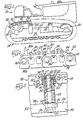
- Fig. 1 illustrates a track-laying tractor 10 employing an improved seal. It is to be understood that the seal may be successfully employed in various machines or other structures having lubricated, sealed hinge points, such as loader linkages or under carriage suspensions, and that tractor 10 of Fig. 1 is exemplary only.
- Tractor 10 includes a frame 12 carried by a pair of endless tracks 14. (Only one track 14 is shown for simplicity.) The track 14 is driven by a sprocket 16 and travels about an idler 20. A plurality of track rollers 22 and carrier rollers 24 on the frame 12 support the track 14.
- Track 14 a portion of which is shown schematically, comprises a plurality of track linkages 26, each having a track shoe 30 secured to a pair of upstanding track links 32 and 33 (not shown in Fig. 1) which are carried by a pair of spaced, transversely extending track pins 34.
- Figs. 2 and 3 show a pair of track linkages 26 in detail.
- a pair of track shoes 30 and 30a extend outwardly from the frame 12 (not shown in Figs. 2 and 3) and each track shoe 30 and 30a includes a mounting plate 40, an upstanding gripping projection 42 extending from the plate 40, a forward lip 44 and an aft lip 46 integral with the plate 40.
- Each forward lip 44 extends upwardly and forwardly from its associated mounting plate 40, and each aft lip 46 extends downwardly and rearwardly from its associated mounting plate 40.
- the aft lip 46 of the forward track shoe 30 lies below the forward lip 44 of the following track shoe 30a.
- Each mounting plate 40 is secured to each of a pair of transversely spaced track links 32 and 33, as by mounting bolts 50.
- Each track link 32 and 33 is pivotally carried by a pair of longitudinally spaced, transversely extending track pins 34, as described below.
- each track link 32 and 33 has a relatively wide central body portion 54, a trailing outer projection 56 of less thickness than the body portion 54, and a leading inner portion 58, also of less thickness than the body portion 54.
- the trailing outer portion 56 of a leading link 32 mates with the leading inner portion 58 of a trailing link 32a to form a structure of a thickness substantially equal to that of the body portion 54.
- Each pin 34 has an elongate bushing 62 positioned thereabout.
- Each link inner portion 58 has an aperture 64 of a diameter sufficient to capture an end 66 of the bushing 62, and each link outer portion 56 has an aperture 67 of a diameter sufficient to capture an end 68 of the pin 34. It is to be understood that the link portions 56 and 58 are press-fitted upon the pin 34 and the bushing 62, respectively, and are rotatably pivotal thereabout.
- Each bushing end 66 has a transverse end wall 74 which abuts a wall 76 on the link outer portion 56, which wall 76 also abuts an outer wall 78 of the link inner portion 58.
- An annular recess 82 is formed in the link outer portion 56 and a lubricated seal 84 is disposed therein, as described below.
- the sealed interface defined by the bushing end wall 74, link wall 76, and the seal 84 disposed therebetween in Fig. 3 is a preferred embodiment of the present invention, and no unnecessary limitations are to be inferred therefrom.
- the seal 84 shown to be disposed within an annular recess 82 in a track link 33, and means (to be described below) associated with the seal 84 to maintain the seal 84 in sealing contact with the wall 74 and the link 33 are shown as a movable side wall of the recess 82, it is to be understood that the scope of the invention broadly encompasses structures having variably spaced wall surfaces utilizing resilient seals with or without annular recessed seats, and may include seal urging means other than the movable recess side wall described below.
- the recess 82 in the link outer element 56 is defined by a fixed radial end wall 86, a fixed annular axial side wall 88 and by a movable annular axial side wall 90 disposed radially inwardly of the fixed side wall 88.
- the movable side wall 90 comprises a frusto-conical axial portion 92 having an integral generally radial lip 94 projecting inwardly from an edge 95 of the axial portion 92 at an angle other than 90°. (Although an acute angle is illustrated, the lip 94 may alternately extend from the edge 95 at an obtuse angle.)
- a thrust ring 100 is slidably disposed about the pin 34 and cooperates with the lip 94 to limit the travel of the bushing 62 toward the outer link element 56.
- the thrust ring 100 includes axially inner and outer radial abutment surfaces 102 and 104, respectively.
- An outer axial cylindrical surface 106 extends between the surfaces 102 and 104.
- the resilient seal 84 is disposed within the recess 82 and engages the fixed walls 86 and 88, the axial movable wall portion 92 and the bushing wall 74.
- the seal 84 of Figs. 4 and 5 comprises a radially outwardly disposed load ring 112 and a radially inwardly disposed crescent-shaped element 114. It is to be understood that the structure of the seal 84 is not critical to the present invention, and no unnecessary limitations should be inferred therefrom.
- the movable wall 90 is shown in detail in its unstressed state in Figs. 6 and 7.
- the axial portion 92 is serrated and includes elongate axially extending apertures 120 alternate ones of which extend radially into the lip 94 to enhance compressibility.
- the link portions 56 and 58 may be momentarily deflected from one another, as shown in Fig. 4. It is desirable to maintain the seal 84 and, more specifically, the crescent-shaped seal element 114 in sealing contact with the bushing wall 74 and the recess walls 86, 88 and 92.
- the preferred length of the axial movable wall portion 92 and the thickness of the lip 94 are chosen such that the combined axial length of the thrust ring 100 and the thickness of the lip 94 is approximately equal to the axial length of the fixed side wall 88 to allow abutment of the bushing wall 74 with the thrust ring outer radial wall 104 (or with the lip 94, depending upon which radial wall the lip 94 pivotally engages when the bushing 62 abuts the outer link 56.
- the improved seal of the present invention provides effective sealing between deflectable elements of a track linkage or like structure over relatively wide ranges of deflection of the linkage elements and reduces loss of lubricant from the seal, thereby prolonging the effective life of linkage elements.
Landscapes
- Engineering & Computer Science (AREA)
- General Engineering & Computer Science (AREA)
- Mechanical Engineering (AREA)
- Chemical & Material Sciences (AREA)
- Combustion & Propulsion (AREA)
- Transportation (AREA)
- Sealing Devices (AREA)
Claims (7)
Applications Claiming Priority (1)
| Application Number | Priority Date | Filing Date | Title |
|---|---|---|---|
| PCT/US1979/000724 WO1981000699A1 (en) | 1979-09-14 | 1979-09-14 | Seal assembly |
Publications (3)
| Publication Number | Publication Date |
|---|---|
| EP0035497A1 EP0035497A1 (de) | 1981-09-16 |
| EP0035497A4 EP0035497A4 (de) | 1982-01-08 |
| EP0035497B1 true EP0035497B1 (de) | 1984-05-16 |
Family
ID=22147700
Family Applications (1)
| Application Number | Title | Priority Date | Filing Date |
|---|---|---|---|
| EP80900591A Expired EP0035497B1 (de) | 1979-09-14 | 1981-03-23 | Dichtungsanordnung |
Country Status (5)
| Country | Link |
|---|---|
| US (1) | US4262970A (de) |
| EP (1) | EP0035497B1 (de) |
| JP (1) | JPS56501124A (de) |
| DE (1) | DE2966998D1 (de) |
| WO (1) | WO1981000699A1 (de) |
Families Citing this family (2)
| Publication number | Priority date | Publication date | Assignee | Title |
|---|---|---|---|---|
| GB2228298A (en) * | 1989-01-31 | 1990-08-22 | Huwood Ltd | Bearing seal |
| CN115013533A (zh) * | 2021-03-03 | 2022-09-06 | 艾志(南京)环保管接技术股份有限公司 | 双弹簧双环组成的剖分式油封 |
Family Cites Families (5)
| Publication number | Priority date | Publication date | Assignee | Title |
|---|---|---|---|---|
| US2641381A (en) * | 1948-11-18 | 1953-06-09 | Hydropress Inc | Sealing means for pressure vessels |
| US2893797A (en) * | 1956-08-08 | 1959-07-07 | Perfect Circle Corp | Piston ring assembly |
| US3390922A (en) * | 1966-04-14 | 1968-07-02 | Caterpillar Tractor Co | Track pin seal |
| US3336086A (en) * | 1966-04-14 | 1967-08-15 | Caterpillar Tractor Co | Track pin seal |
| DE2808159A1 (de) * | 1978-02-25 | 1979-09-06 | Viehmann & Co Intertrac | Abdichtung einer bolzenlagerung einer gleiskette |
-
1979
- 1979-09-14 US US06/134,620 patent/US4262970A/en not_active Expired - Lifetime
- 1979-09-14 WO PCT/US1979/000724 patent/WO1981000699A1/en not_active Ceased
- 1979-09-14 DE DE8080900591T patent/DE2966998D1/de not_active Expired
- 1979-09-14 JP JP80500721A patent/JPS56501124A/ja active Pending
-
1981
- 1981-03-23 EP EP80900591A patent/EP0035497B1/de not_active Expired
Also Published As
| Publication number | Publication date |
|---|---|
| DE2966998D1 (en) | 1984-06-20 |
| EP0035497A4 (de) | 1982-01-08 |
| US4262970A (en) | 1981-04-21 |
| EP0035497A1 (de) | 1981-09-16 |
| WO1981000699A1 (en) | 1981-03-19 |
| JPS56501124A (de) | 1981-08-13 |
Similar Documents
| Publication | Publication Date | Title |
|---|---|---|
| US4262914A (en) | End face seal assembly | |
| US4364443A (en) | Suspension apparatus for track-type vehicles | |
| US3948574A (en) | Joint with a combined seal and bushing | |
| US2699974A (en) | Sealing and spacing means for hinge connections | |
| US4062550A (en) | Seal assembly with backup ring | |
| EP0221585B1 (de) | Endabdichtungsringzusammenbau | |
| US4364572A (en) | Seal assembly with load ring | |
| US4568090A (en) | Oil seal for lubricated tracks on a crawler tractor | |
| CN205615600U (zh) | 用于密封组件的负载环、密封组件及履带销接头组件 | |
| US4209204A (en) | Two-piece seal for track chain joints | |
| JPS6121865B2 (de) | ||
| JP4116187B2 (ja) | 履帯 | |
| US4262970A (en) | Seal assembly | |
| CA1071674A (en) | Track joint with combined thrust member and seal members | |
| US4030730A (en) | Symmetrical seal assembly for a hinge joint | |
| JPH0293170A (ja) | 履帯シール | |
| US4004855A (en) | Articulated joint including seals maintained by wedge | |
| KR100480392B1 (ko) | 크롤러 벨트 및 크롤러 벨트에 사용하는 실 | |
| US4240642A (en) | Belleville spring-loaded crescent seal | |
| CA1128568A (en) | Mechanical seal assembly | |
| US3787098A (en) | Track link with eccentric seal counterbore | |
| EP0030085B1 (de) | Stirnflächen-Druckdichtung für Gleiskettengelenke | |
| CA1074838A (en) | Track joint with combined thrust and seal members | |
| WO2020055799A1 (en) | Lip seal | |
| GB2095347A (en) | Seals |
Legal Events
| Date | Code | Title | Description |
|---|---|---|---|
| PUAI | Public reference made under article 153(3) epc to a published international application that has entered the european phase |
Free format text: ORIGINAL CODE: 0009012 |
|
| 17P | Request for examination filed |
Effective date: 19810309 |
|
| AK | Designated contracting states |
Kind code of ref document: A1 Designated state(s): DE FR GB |
|
| RBV | Designated contracting states (corrected) |
Designated state(s): DE FR GB |
|
| GRAA | (expected) grant |
Free format text: ORIGINAL CODE: 0009210 |
|
| AK | Designated contracting states |
Kind code of ref document: B1 Designated state(s): DE FR GB |
|
| PGFP | Annual fee paid to national office [announced via postgrant information from national office to epo] |
Ref country code: DE Payment date: 19840612 Year of fee payment: 6 |
|
| PGFP | Annual fee paid to national office [announced via postgrant information from national office to epo] |
Ref country code: FR Payment date: 19840618 Year of fee payment: 6 |
|
| REF | Corresponds to: |
Ref document number: 2966998 Country of ref document: DE Date of ref document: 19840620 |
|
| ET | Fr: translation filed | ||
| PLBE | No opposition filed within time limit |
Free format text: ORIGINAL CODE: 0009261 |
|
| STAA | Information on the status of an ep patent application or granted ep patent |
Free format text: STATUS: NO OPPOSITION FILED WITHIN TIME LIMIT |
|
| 26N | No opposition filed | ||
| REG | Reference to a national code |
Ref country code: GB Ref legal event code: 732 |
|
| PG25 | Lapsed in a contracting state [announced via postgrant information from national office to epo] |
Ref country code: FR Free format text: LAPSE BECAUSE OF NON-PAYMENT OF DUE FEES Effective date: 19870527 |
|
| PG25 | Lapsed in a contracting state [announced via postgrant information from national office to epo] |
Ref country code: DE Effective date: 19870602 |
|
| GBPC | Gb: european patent ceased through non-payment of renewal fee | ||
| REG | Reference to a national code |
Ref country code: FR Ref legal event code: ST |
|
| REG | Reference to a national code |
Ref country code: FR Ref legal event code: TP |
|
| PG25 | Lapsed in a contracting state [announced via postgrant information from national office to epo] |
Ref country code: GB Effective date: 19881118 |