EP0035568A1 - Machines de moulage pour briques - Google Patents
Machines de moulage pour briques Download PDFInfo
- Publication number
- EP0035568A1 EP0035568A1 EP80900184A EP80900184A EP0035568A1 EP 0035568 A1 EP0035568 A1 EP 0035568A1 EP 80900184 A EP80900184 A EP 80900184A EP 80900184 A EP80900184 A EP 80900184A EP 0035568 A1 EP0035568 A1 EP 0035568A1
- Authority
- EP
- European Patent Office
- Prior art keywords
- metallic mold
- metallic
- mould
- bricks
- support
- Prior art date
- Legal status (The legal status is an assumption and is not a legal conclusion. Google has not performed a legal analysis and makes no representation as to the accuracy of the status listed.)
- Granted
Links
Images

Classifications
-
- B—PERFORMING OPERATIONS; TRANSPORTING
- B28—WORKING CEMENT, CLAY, OR STONE
- B28B—SHAPING CLAY OR OTHER CERAMIC COMPOSITIONS; SHAPING SLAG; SHAPING MIXTURES CONTAINING CEMENTITIOUS MATERIAL, e.g. PLASTER
- B28B17/00—Details of, or accessories for, apparatus for shaping the material; Auxiliary measures taken in connection with such shaping
- B28B17/009—Changing the forming elements, e.g. exchanging moulds, dies
-
- B—PERFORMING OPERATIONS; TRANSPORTING
- B28—WORKING CEMENT, CLAY, OR STONE
- B28B—SHAPING CLAY OR OTHER CERAMIC COMPOSITIONS; SHAPING SLAG; SHAPING MIXTURES CONTAINING CEMENTITIOUS MATERIAL, e.g. PLASTER
- B28B3/00—Producing shaped articles from the material by using presses; Presses specially adapted therefor
- B28B3/02—Producing shaped articles from the material by using presses; Presses specially adapted therefor wherein a ram exerts pressure on the material in a moulding space; Ram heads of special form
-
- B—PERFORMING OPERATIONS; TRANSPORTING
- B30—PRESSES
- B30B—PRESSES IN GENERAL
- B30B15/00—Details of, or accessories for, presses; Auxiliary measures in connection with pressing
- B30B15/02—Dies; Inserts therefor; Mounting thereof; Moulds
- B30B15/026—Mounting of dies, platens or press rams
-
- B—PERFORMING OPERATIONS; TRANSPORTING
- B30—PRESSES
- B30B—PRESSES IN GENERAL
- B30B15/00—Details of, or accessories for, presses; Auxiliary measures in connection with pressing
- B30B15/02—Dies; Inserts therefor; Mounting thereof; Moulds
- B30B15/028—Loading or unloading of dies, platens or press rams
Definitions
- This invention relates to a forming machine for bricks, etc.
- the invention provides a new concept in reducing the excessively long time required for changing metallic molds in the conventional brick forming machines in order to achieve higher efficiency in brick production.
- the metallic mold sits on the metallic mold support and receives the brick material into its inside.
- the upper plunger is driven by the hydraulic cylinder placed on the upper center of the machine to press the brick material in the metallic mold between itself and the stationary lower plunger.
- the metallic mold support is driven by the hydraulic cylinders mounted on the right and left co- lumns of the machine to fasten the metallic mold while the brick is being pressed.
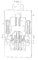
- the metallic mold (1) receives brick material thrown into it and it sits on the metallic mold support (4).
- the upper plunger (2) is driven by the hydraulic cylinders (9) mounted on the upper frame of the machine through the pusher block (8) to press the material downwards in the metallic mold (1) between itself and the lower plunger (3) that is stationary.
- the metallic mold (1), metallic mold support (4) and plungers (2) and (3) are of such dimension as to form a group of components fitted together, and they are as a whole placed in and out of the metallic molds support (4) rapidly as described below, which saves time wasted for changing the metallic mold (1) and plungers (2) and (3) in the conventional forming machines for bricks, etc.
- the metallic mold support (4) is shaped a square frame with its one side open like the letter U laid flat on its face.
- the metallic mold (1), upper and lower plungers (2) and (3) forming a combination of componetns are put together beforehand in the operation of the machine and they are placed inside the metallic mold support (4), and after the forming operation they are withdrawn through the opening.
- the protrusions of the metallic mold (1) are above it and the upper and lower plungers (2) and (3) which have in common the center line of the metallic mold (1) and the metallic mold (1) can freely move on the transfer truck (16) in the direction taht is perpendicular to the sheet of paper of the figure.
- the bottom flange of the metallic mold support (4) will contact the protrusions of the metallic mold (1).
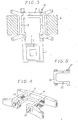
- the transfer truck (16) has the upward protruding pins (15), and they fit into the- holes (14) of the metallic mold (1) to position it correctly.
- the lower end of the transfer truck (16). has rollers (17), which rolls back and forth on the transfer rails .(19) and the positioning rails (7).
- the transfer truck is also shaped as shown in Fig. 5 like the letter U laid flat on its face to give an opening for the lower plunger (3) to pass through.
- the metallic mold (1) and the upper and lower plungers (2) and (3) to replace the old ones move on the transfer truck (16) through the openining of the U-shaped metallic mold support (4) into the metallime mold support (4) and their center line is aligned with the center line of the metallic mold support (4) and the transfer truck (16) stops at the correct position by the stopper (18) placed on the positioning rails (7).
- the metallic mold support (4) is raised by the hydraulic cylinders (5).
- the engagement of the pins (12) and the holes (13) guides the protrusions of the metallic mold (1) to place it correctly on the metallic mold support (4).
- the metallic pattern (1) and the upper and lower plungers (2) and (3) are lifted off the transfer truck (16), and the truck (16) is shifted to the left in Fig. 2 to be out of the machine.
- the metallic mold (1) on the support (4) is fastened to it by the advance of the hydraulic cylinders (10) and wedges (11), and after this the metallic mold support (4) is lifted up to mount the upper plunger (2) on to the pressure block (8). Then the metallic mold support (4) is lowered until the bottom of the lower plunger hits the bottom face of the frame (6). With the lower plunger (3) on the frame (6), the former is fixed on the latter with the bolts, etc. This concludes the installation of a new metallic mold and the plungers.
- the removal of the metallic mold (1) out of the machine follows the sters as described above for the installation of a new one in the reverse order.
Landscapes
- Engineering & Computer Science (AREA)
- Mechanical Engineering (AREA)
- Chemical & Material Sciences (AREA)
- Ceramic Engineering (AREA)
- Manufacturing & Machinery (AREA)
- Press-Shaping Or Shaping Using Conveyers (AREA)
Abstract
Applications Claiming Priority (2)
| Application Number | Priority Date | Filing Date | Title |
|---|---|---|---|
| JP4924979A JPS55140512A (en) | 1979-04-20 | 1979-04-20 | Molding machine used for brick* etc* |
| JP49249/79 | 1979-04-20 |
Publications (3)
| Publication Number | Publication Date |
|---|---|
| EP0035568A4 EP0035568A4 (fr) | 1981-09-07 |
| EP0035568A1 true EP0035568A1 (fr) | 1981-09-16 |
| EP0035568B1 EP0035568B1 (fr) | 1984-02-15 |
Family
ID=12825568
Family Applications (1)
| Application Number | Title | Priority Date | Filing Date |
|---|---|---|---|
| EP80900184A Expired EP0035568B1 (fr) | 1979-04-20 | 1980-11-04 | Machines de moulage pour briques |
Country Status (4)
| Country | Link |
|---|---|
| EP (1) | EP0035568B1 (fr) |
| JP (1) | JPS55140512A (fr) |
| DE (1) | DE2966698D1 (fr) |
| WO (1) | WO1980002250A1 (fr) |
Cited By (7)
| Publication number | Priority date | Publication date | Assignee | Title |
|---|---|---|---|---|
| EP0169678A1 (fr) * | 1984-07-11 | 1986-01-29 | CHIYODA TECHNICAL & INDUSTRIAL CO. LTD. | Procédé et dispositif pour rapporter des cadres de moulage et plateaux de serrage dans des presses rapides pour objets en béton |
| EP0259903A1 (fr) * | 1986-09-02 | 1988-03-16 | DANIELI & C. OFFICINE MECCANICHE S.p.A. | Dispositif pour mouvoir des bennes dans une zône de chargement de déchets métalliques |
| EP0260730A1 (fr) * | 1986-09-02 | 1988-03-23 | DANIELI & C. OFFICINE MECCANICHE S.p.A. | Presses pour le pressage de déchets métalliques dans des skips et procédé pour mouvoir des skips sous les presses |
| WO1989010257A1 (fr) * | 1988-04-28 | 1989-11-02 | The Upjohn Company | Presse a comprimes |
| FR2700137A1 (fr) * | 1993-01-05 | 1994-07-08 | Allibert Ind | Dispositif pour la fixation de moules d'injection sur les plateaux d'une presse. |
| EP0753396A3 (fr) * | 1995-07-14 | 1997-10-29 | Siti Spa | Dispositif utilisable dans un appareil de pressage |
| FR2857899A1 (fr) * | 2003-07-22 | 2005-01-28 | Cogema | Presse a compacter |
Families Citing this family (4)
| Publication number | Priority date | Publication date | Assignee | Title |
|---|---|---|---|---|
| JPH0755488B2 (ja) * | 1989-12-06 | 1995-06-14 | 株式会社三石深井鐵工所 | 金型交換方法及び装置 |
| JP5256065B2 (ja) * | 2009-01-30 | 2013-08-07 | 株式会社タイガーマシン製作所 | 型枠換え装置 |
| CN103302726A (zh) * | 2013-06-14 | 2013-09-18 | 王庆起 | 一种生产打孔水泥预制品的制砖机 |
| CN106900890B (zh) * | 2017-02-13 | 2023-09-26 | 湖北省农业科学院果树茶叶研究所 | 一种全自动砖茶成型设备 |
Family Cites Families (13)
| Publication number | Priority date | Publication date | Assignee | Title |
|---|---|---|---|---|
| FR1312900A (fr) * | 1962-01-29 | 1962-12-21 | Danly Machine Specialties | Dispositif de serrage pour une presse à changement rapide de matrices |
| US3335657A (en) * | 1966-05-26 | 1967-08-15 | Minster Machine Co | Press with sliding bolster and die clamp |
| DE1945864C3 (de) * | 1968-09-13 | 1973-04-26 | Hitachi Ltd | Vertikalschere |
| US3559522A (en) * | 1969-01-28 | 1971-02-02 | Manco Mfg Co | Interchangeable die units for hydraulic presses |
| JPS4924506B1 (fr) * | 1969-05-14 | 1974-06-24 | ||
| GB1243864A (en) * | 1969-08-22 | 1971-08-25 | Frederik Isaakovich Kaganovsky | Movable tool loading table for a hydraulic press |
| DE1955193C3 (de) * | 1969-11-03 | 1975-06-19 | Trumpf & Co, 7257 Ditzingen | Halter zum Einsetzen und Entnehmen eines Werkzeuges in eine bzw. aus einer Maschine |
| JPS4844307A (fr) * | 1971-08-02 | 1973-06-26 | ||
| JPS5242132Y2 (fr) * | 1971-07-19 | 1977-09-24 | ||
| JPS5234787B2 (fr) * | 1971-08-25 | 1977-09-05 | ||
| DE2544711C3 (de) * | 1975-10-07 | 1983-06-01 | Georg 7203 Fridingen Fellner | Schnellspannwerkzeug für Schmiedepressen |
| DE2613213A1 (de) * | 1976-03-27 | 1977-10-06 | Amsted Siemag Kette Gmbh | Presse oder stanzmaschine |
| JPS5336779A (en) * | 1976-09-17 | 1978-04-05 | Yoshitsuka Seiki Kk | Powder molding machine |
-
1979
- 1979-04-20 JP JP4924979A patent/JPS55140512A/ja active Granted
- 1979-12-24 WO PCT/JP1979/000324 patent/WO1980002250A1/fr not_active Ceased
- 1979-12-24 DE DE8080900184T patent/DE2966698D1/de not_active Expired
-
1980
- 1980-11-04 EP EP80900184A patent/EP0035568B1/fr not_active Expired
Cited By (11)
| Publication number | Priority date | Publication date | Assignee | Title |
|---|---|---|---|---|
| EP0169678A1 (fr) * | 1984-07-11 | 1986-01-29 | CHIYODA TECHNICAL & INDUSTRIAL CO. LTD. | Procédé et dispositif pour rapporter des cadres de moulage et plateaux de serrage dans des presses rapides pour objets en béton |
| EP0259903A1 (fr) * | 1986-09-02 | 1988-03-16 | DANIELI & C. OFFICINE MECCANICHE S.p.A. | Dispositif pour mouvoir des bennes dans une zône de chargement de déchets métalliques |
| EP0260730A1 (fr) * | 1986-09-02 | 1988-03-23 | DANIELI & C. OFFICINE MECCANICHE S.p.A. | Presses pour le pressage de déchets métalliques dans des skips et procédé pour mouvoir des skips sous les presses |
| US4799426A (en) * | 1986-09-02 | 1989-01-24 | Danieli & C. Officine Meccaniche Spa | System and method for moving skips and pressing scrap in a skip |
| US4815371A (en) * | 1986-09-02 | 1989-03-28 | Danieli & C. Officine Meccaniche Spa | Method for pressing scrap in a skip |
| WO1989010257A1 (fr) * | 1988-04-28 | 1989-11-02 | The Upjohn Company | Presse a comprimes |
| FR2700137A1 (fr) * | 1993-01-05 | 1994-07-08 | Allibert Ind | Dispositif pour la fixation de moules d'injection sur les plateaux d'une presse. |
| EP0753396A3 (fr) * | 1995-07-14 | 1997-10-29 | Siti Spa | Dispositif utilisable dans un appareil de pressage |
| EP0753397A3 (fr) * | 1995-07-14 | 1997-10-29 | Siti Spa | Dispositif utilisable dans un appareil de pressage |
| FR2857899A1 (fr) * | 2003-07-22 | 2005-01-28 | Cogema | Presse a compacter |
| US7178455B2 (en) | 2003-07-22 | 2007-02-20 | Compagnie Generale Des Matieres Nucleaires | Compacting press |
Also Published As
| Publication number | Publication date |
|---|---|
| DE2966698D1 (en) | 1984-03-22 |
| EP0035568B1 (fr) | 1984-02-15 |
| WO1980002250A1 (fr) | 1980-10-30 |
| EP0035568A4 (fr) | 1981-09-07 |
| JPS55140512A (en) | 1980-11-04 |
| JPS5745642B2 (fr) | 1982-09-29 |
Similar Documents
| Publication | Publication Date | Title |
|---|---|---|
| US4631015A (en) | Molding apparatus with replaceable plunger and die set | |
| EP0035568A1 (fr) | Machines de moulage pour briques | |
| GB2032311A (en) | Sand moulding | |
| CN106890900A (zh) | 一种厚板长短组合件u型冲压压弯模具结构及操作方法 | |
| US2872861A (en) | Forming or molding apparatus | |
| GB1179405A (en) | Process for Producing a Concrete Article | |
| CN216372689U (zh) | 一种透水砖模具固定装置 | |
| CN211539200U (zh) | 一种双料壳体拉伸模具 | |
| CN221391893U (zh) | 一种热压成型装置 | |
| JPH0210126Y2 (fr) | ||
| US4266922A (en) | Mold for manufacturing abrasive segments | |
| KR100278088B1 (ko) | 조립식 타일블럭의 제조방법 및 장치 | |
| EP0468577B1 (fr) | Installation à productivité élevée pour la fabrication de carreaux en céramique en général | |
| CN218963962U (zh) | 一种上下对压抽屉式自动造型机 | |
| CN219749363U (zh) | 一种生产广告标识的压印装置 | |
| CN223223596U (zh) | 一种拼接式钢包浇筑模具 | |
| CN218196375U (zh) | 一种便于脱模的平板硫化机 | |
| CN213793768U (zh) | 矿用锚杆支护托盘一次成型模具 | |
| JPS5912110Y2 (ja) | 鋳型造型機における型抜き装置 | |
| JPS6462264A (en) | Low-pressure casting machine | |
| CN210648393U (zh) | 一种便于人工操作的型砂成型装置 | |
| CN101817028A (zh) | 双头管接头的冷挤压模具 | |
| CN210138985U (zh) | 集装箱顶板冲压成型的模具 | |
| JPS604740Y2 (ja) | サイドフレ−ム型プレスに於ける上熱盤の可調整的取付装置 | |
| JP2891708B2 (ja) | プレス成形装置 |
Legal Events
| Date | Code | Title | Description |
|---|---|---|---|
| PUAI | Public reference made under article 153(3) epc to a published international application that has entered the european phase |
Free format text: ORIGINAL CODE: 0009012 |
|
| AK | Designated contracting states |
Designated state(s): DE GB |
|
| 17P | Request for examination filed |
Effective date: 19810428 |
|
| GRAA | (expected) grant |
Free format text: ORIGINAL CODE: 0009210 |
|
| AK | Designated contracting states |
Designated state(s): DE GB |
|
| REF | Corresponds to: |
Ref document number: 2966698 Country of ref document: DE Date of ref document: 19840322 |
|
| PLBE | No opposition filed within time limit |
Free format text: ORIGINAL CODE: 0009261 |
|
| STAA | Information on the status of an ep patent application or granted ep patent |
Free format text: STATUS: NO OPPOSITION FILED WITHIN TIME LIMIT |
|
| 26N | No opposition filed | ||
| PGFP | Annual fee paid to national office [announced via postgrant information from national office to epo] |
Ref country code: GB Payment date: 19961211 Year of fee payment: 18 |
|
| PGFP | Annual fee paid to national office [announced via postgrant information from national office to epo] |
Ref country code: DE Payment date: 19961231 Year of fee payment: 18 |
|
| PG25 | Lapsed in a contracting state [announced via postgrant information from national office to epo] |
Ref country code: GB Free format text: LAPSE BECAUSE OF NON-PAYMENT OF DUE FEES Effective date: 19971224 |
|
| GBPC | Gb: european patent ceased through non-payment of renewal fee |
Effective date: 19971224 |
|
| PG25 | Lapsed in a contracting state [announced via postgrant information from national office to epo] |
Ref country code: DE Free format text: LAPSE BECAUSE OF NON-PAYMENT OF DUE FEES Effective date: 19980901 |