EP0035600A1 - Steuerungsvorrichtung für ein Schiff - Google Patents
Steuerungsvorrichtung für ein Schiff Download PDFInfo
- Publication number
- EP0035600A1 EP0035600A1 EP19800200169 EP80200169A EP0035600A1 EP 0035600 A1 EP0035600 A1 EP 0035600A1 EP 19800200169 EP19800200169 EP 19800200169 EP 80200169 A EP80200169 A EP 80200169A EP 0035600 A1 EP0035600 A1 EP 0035600A1
- Authority
- EP
- European Patent Office
- Prior art keywords
- propeller
- housing
- ship
- main spindle
- spindle
- Prior art date
- Legal status (The legal status is an assumption and is not a legal conclusion. Google has not performed a legal analysis and makes no representation as to the accuracy of the status listed.)
- Ceased
Links
- 230000001154 acute effect Effects 0.000 claims abstract description 4
- XLYOFNOQVPJJNP-UHFFFAOYSA-N water Substances O XLYOFNOQVPJJNP-UHFFFAOYSA-N 0.000 claims description 11
- 239000010720 hydraulic oil Substances 0.000 claims description 3
- 239000003921 oil Substances 0.000 description 15
- 230000001141 propulsive effect Effects 0.000 description 7
- 238000007789 sealing Methods 0.000 description 6
- 238000010276 construction Methods 0.000 description 4
- 239000000969 carrier Substances 0.000 description 1
- 239000012530 fluid Substances 0.000 description 1
- 230000000149 penetrating effect Effects 0.000 description 1
Images

Classifications
-
- B—PERFORMING OPERATIONS; TRANSPORTING
- B63—SHIPS OR OTHER WATERBORNE VESSELS; RELATED EQUIPMENT
- B63H—MARINE PROPULSION OR STEERING
- B63H25/00—Steering; Slowing-down otherwise than by use of propulsive elements; Dynamic anchoring, i.e. positioning vessels by means of main or auxiliary propulsive elements
- B63H25/42—Steering or dynamic anchoring by propulsive elements; Steering or dynamic anchoring by propellers used therefor only; Steering or dynamic anchoring by rudders carrying propellers
-
- F—MECHANICAL ENGINEERING; LIGHTING; HEATING; WEAPONS; BLASTING
- F02—COMBUSTION ENGINES; HOT-GAS OR COMBUSTION-PRODUCT ENGINE PLANTS
- F02B—INTERNAL-COMBUSTION PISTON ENGINES; COMBUSTION ENGINES IN GENERAL
- F02B3/00—Engines characterised by air compression and subsequent fuel addition
- F02B3/06—Engines characterised by air compression and subsequent fuel addition with compression ignition
Definitions
- the invention relates to a device for steering a ship's bow, comprising a propeller housing arranged in the bottom in the interior part of the ship, a propeller shaft journalled in propeller-shaft bearing means connected with the propeller housing and rotatably driven by driving means and a propelling screw fastened to said shaft.
- the propeller housing is in this case a tun-I nel having an inlet port and an outlet port located at a distance from the former, both ports being located in the bottom of the ship.
- the propelling screw is mounted in the tunnel.
- the propelling screw supplies a propulsive force by sucking in water through the inlet port and by pressing it out through the outlet port.
- the direction in which the propulsive force is operating can be varied for steering the ship's bow by means of a guide-blade grating rotatably journalled in the outlet port of the tunnel, said grating deflecting the water pressed out and providing a horizontal motion component. By turning the guide-blade grating the direction of this horizontal motion component is varied.
- this construction is excessively bulky and complicated.
- the object of the invention is to provide a device of the kind set forth having a simple construction and small dimensions, whereas it provides nevertheless the same satisfactory manoeuvrability of the ship, in which the device is built in, as the known device does.
- the propeller housing is essentially rotation-symmetrical to a standing axis of symmetry and open and tapering towards the bottom of the ship, in that a main spindle is rotatably journalled in and coaxial with the housing with the aid of main-spindle bearing means, in that the propeller shaft is transversely journalled with the aid of propeller-shaft bearing means so as to be rotatable at an acute angle to the main spindle and in that the main spindle with the propelling screw is rotatable by rotary means.
- all movable parts with the exception of the driving means for the propelling screw constitute a compact unit.
- the functions of supplying propulsive force and of varying the operative direction of said propulsive force are both satisfactorily performed by said unit
- the driving means comprise a hydromotor rigidly secured to the main spindle and driving the propeller shaft and a hydropump communicating with said motor through hydraulic conduits and driven by a diesel aggregate, the construction is even considerably simpler.
- the hydraulic inlet and outlet conduits for the hydromotor extend through the main spindle, there is no need to use vulnerable flexible conduits.
- the propeller screw is surrounded by a jet tube, as a result of which the efficiency of the propeller screw and the manoevrability of the ship are improved.
- the rotary means may comprise an electric motor remote-controlled from the bridge.
- the ship 1 is equipped in the bottom 3 near the bow 2 with a device 4 according to the invention for steering the bow 2 of the ship 1.
- a device 4 for steering the bow 2 of the ship 1.
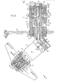
- the device 4 comprises a substantially rotation-symmetrical propeller housing 5 welded in the bottom 3 and having a standing axis of symmetry 11.
- the figures show the propeller housing 5 in the form of a truncated cone. At the top the propeller housing 5 has a cover 6. As an alternative, other shapes, for example, part of a sphere are possible.
- the propeller housing 5 is tapering downwards and open on the bottom side.
- a main spindle 8 is journalled by main-spindle bearing means 7, so as to be rotatable about the axis of symmetry 11 of the propeller housing 5.
- the main-spindle bearing means 7 comprise a bearing housing 47 welded to the cover 6, in which housing a ball bearing 48 and a sliding bearing 49 are mounted.
- the ball bearing 48 is fixed axially in the bearing housing 47 3 on the bottom side by a ring 56 supported from a shoulder 55 and on the top side by a top cover 51 fastened by bolts 50 to the bearing housing 47.
- the sliding bearing 49 is supported on the bottom side by a lower cover 53 fastened by bolts 52 to the bearing housing 47.
- the ball bearing 48 is axially fixed to the main spindle 8, since it is locked between a bearing nut 54 and a shoulder 57 of the main spindle 8.
- a propeller shaft 9 is rotatably journalled with the aid of propeller-shaft bearing means 14 at an acute angle a to the main spindle 8 and connected herewith.
- the angle a is of the order of magnitude of 30 to 60 degrees, particularly 40 degrees.
- a propelling screw 10 is secured by bolts 41.
- the propeller-shaft bearing means 14 comprise two self-adjusting barrel bearings 15, 16 mounted in a bearing sleeve 40, said bearings absorbing both the radial forces and the axial propulsive force.
- the propeller shaft 9 and hence the propelling screw 10 are rotatably driven by driving means 17.
- these driving means-17 are hydraulic driving means.
- the driving means 17 shown comprise a hydromotor 18 having a housing 42, a rotor (not shown) of known type journalled in the housing 42, an output shaft 19 and an inlet port 26 and an outlet port 27 for hydraulic fluid.
- the housing 42 At one end of the output shaft 19 the housing 42 has secured to it the bearing sleeve 40 by means of bolts 44.
- the housing 42 is rigidly fastened by bolts 43 to the part 79 of the main spindle 8 arranged at the angle a.
- the output shaft 19 of the hydromotor 18 comprises a portion 46 having external key-toothing, which engages a central hole 83 in the propeller shaft 9 having internal key-way toothing. In this way the shaft 19 is only loaded by torsional forces instead of being loaded by thrust forces, which are transferred via the bearings 15, 16 and the bearing sleeve 40 to the housing 42 of the hydromotor 18.
- the hydromotor 18 is fed by pressurized oil supplied by a pump 21 driven by a diesel aggregate 20.
- the oil is passed from a sump 22 though a conduit 45 towards the pump 21, which presses it into a supply conduit 24.
- the supply conduit 24 includes an overflow valve 25 having an open and a closed position.
- the rate of flow to the hydromotor 18 is controlled by controlling the speed of the diesel engine 20.
- the overflow valve 25 is in closed position during operation and is opened when the diesel engine 20 is working in the idle state and the screw 10 has to stand still.
- the supply conduit 24 communicates with an inlet channel 12 in the main-spindle bearing means 7.
- the inlet channel 12 communicates with a first annular chamber 58 formed between a sealing sleeve 29 and the bore 30 of the bearing house 47, said chamber communicating through bores 59 in the sealing sleeve 29 with a second annular chamber 60 between the main spindle 8 and the sealing sleeve 29.
- the main spindle 8 has a central bore 61 closed at the top by a screw plug 62.
- the central bore 61 has below a portion 63 of larger diameter.
- This portion 63 is divided by a sleeve 64 rigidly fixed in the main spindle 8 into a cylindrical supply channel portion 65 and an annular outlet channel portion 66 coaxial with the former, said portions being completely separated from one another by the sleeve 64.
- the pressurized oil flows from the second annular chamber 60 through transverse bores 67 in the main spindle 8, the portion 82 of the central bore 61 and the supply channel portion 65 towards the inlet 26 of the hydromotor 18. After having passed through the motor 18 the oil flows out of the outlet 27 into a draining channel portion 68, which communicates with the outlet channel portion 66.
- the oil flows through transverse bores 69 in the main spindle 8 into a third annular chamber 70 formed between the bearing housing 47 and the main spindle 8 communicating with the outlet channel 13. From this channel the oil gets into the drain conduit 28. The oil flows through a filter 23 connnected with the drain conduit 28 back into the sump 22 or back to the pump 21.
- the sliding bearing 49 of the main spindle 8 is lubricated by hydraulic oil supplied on the bottom side through the oil channel 71 and on the top side from the third annular chamber 70.
- the bearings 15 and 16 of the propeller-shaft bearing means are also lubricated by hydraulic oil.
- the bearing sleeve 40 includes an G-ring 73 to prevent oil from leaking away or water from getting in.
- the sump 22 is mounted at such a level in the ship 1 that the oil level in the sump 22 is always above the waterline 37 in the loaded state. Therefore the oil pressure prevailing anywhere in the part of the device 4 located in the water is higher than the water pressure so that water is prevented from penetrating from the outside into the propeller-shaft bearing means 14 and into the sliding bearing 49 of the main-spindle bearing means 7.
- the sealing sleeve 29, the sliding bearing 49, the sleeve 64 and the main spindle 8 and in the fastening base of the hydromotor 18 sealing means 73 are provided for sealing the channels and spaces conducting the oil with respect to one another and to the surroundings.
- the propelling screw 10 may be surrounded by a jet tube 31, which improves the efficiency of the propelling screw 10 and hence the manoeuvrability of the ship 1.
- the jet tube 31 is connected by means of supports 74 with the main spindle 8.
- the supports 74 have a low flow resistance in the direction of flow 75 of the water.
- the main spindle 8 is rotatably journalled in the main-spindle bearing means 7.
- rotary means 32 are provided in order to be able to turn the main spindle 8 with the hydromotor 18 and the propelling screw 10 and hence to vary the direction in which the propulsive force produced by the screw 10 is operating.
- said means comprise an electric motor 35 fastened to the propeller housing 5, a reduction driving gear 39 coupled herewith, a chain sprocket 34 fastened to the output shaft 76 thereof and a chain sprocket 33 coupled with the former through a chain 36 shown schematically and fastened to the main spindle 8.
- the diesel aggregate 20, the overflow valve 25 and the electric motor 35 are preferably connected with control- members 80 shown schematically on the bridge 86 so that the ship 1 can be readily steered from the bridge 86 even in narrow waterways.
- a position pick-up 38 is connected, which is coupled with a position indicator 81 on the bridge 86 with the aid of which the direction, in which the propulsive force of the device 4 is operating, can be displayed on the bridge 86.
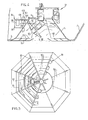
- the propeller housing 5 of the embodiment shown in figs. 4 and 5 has the shape of a truncated, octogonal pyramid having eight side faces 90 rather than that of a truncated cone.
- the housing 5 has an eight-sided grating 91.
- the grating 91 comprises radially extending carriers 93, between which guide blades 92 are arranged.
- the guide blades 92 form in the grating 91 a plurality of horizontal sections of eight-sided pyramid faces, said sections being concentrical with one another and with the propeller housing 5.
- the water .stream produced by the propellling screw 10 obtains a stronger, horizontal component by the guide blades 92 of the grating 91.
- Fig. 4 shows an exhaust system 94 communicating with the propeller housing 5. This system serves for evacuating air from the propeller housing 5, which air may penetrate into the housing when the waterline of the ship 1, for example, in the no-load state, is lower than the level of the cover 6.
- the exhaust sytem 94 comprises a level switch 99 arranged in a suction housing 95 for switching on and off an exhaust pump 103 (not shown) in dependence upon the water level 98.
- the suction housing 95 communicates through 'slot-shaped openings 96, 97 with the interior of the propeller housing 5.
- the exhaust pump 103 is connected through a suction conduit 102 with the valve housing 101 of a valve 104.
- the valve housing 101 comprises a floating ball 100, which closes the suction conduit 102 when the water level 98 is sufficiently high.
- an exhaust system 94 is not limited to a device having an eight-sided propeller housing 5.
- the system may as well be employed with a frustoconical propeller housing 5.
- a jet tube may also be used in an eight-sided propeller housing 5.
Landscapes
- Chemical & Material Sciences (AREA)
- Engineering & Computer Science (AREA)
- Combustion & Propulsion (AREA)
- Mechanical Engineering (AREA)
- Ocean & Marine Engineering (AREA)
- Exhaust Silencers (AREA)
Priority Applications (1)
| Application Number | Priority Date | Filing Date | Title |
|---|---|---|---|
| EP19800200169 EP0035600A1 (de) | 1980-02-27 | 1980-02-27 | Steuerungsvorrichtung für ein Schiff |
Applications Claiming Priority (1)
| Application Number | Priority Date | Filing Date | Title |
|---|---|---|---|
| EP19800200169 EP0035600A1 (de) | 1980-02-27 | 1980-02-27 | Steuerungsvorrichtung für ein Schiff |
Publications (1)
| Publication Number | Publication Date |
|---|---|
| EP0035600A1 true EP0035600A1 (de) | 1981-09-16 |
Family
ID=8186963
Family Applications (1)
| Application Number | Title | Priority Date | Filing Date |
|---|---|---|---|
| EP19800200169 Ceased EP0035600A1 (de) | 1980-02-27 | 1980-02-27 | Steuerungsvorrichtung für ein Schiff |
Country Status (1)
| Country | Link |
|---|---|
| EP (1) | EP0035600A1 (de) |
Cited By (6)
| Publication number | Priority date | Publication date | Assignee | Title |
|---|---|---|---|---|
| FR2541963A1 (fr) * | 1983-03-04 | 1984-09-07 | Goetaverken Arendal Ab | Navire a coques paralleles |
| EP0159144A1 (de) * | 1984-02-27 | 1985-10-23 | Niigata Engineering Co., Ltd. | Azimutalpropeller für Schiffe |
| GB2179312A (en) * | 1985-08-19 | 1987-03-04 | Hollming Oy | Turnable propeller assembly |
| WO2000037308A1 (en) * | 1998-12-22 | 2000-06-29 | Kamewa Finland Oy | Turnable propeller device for a ship, an offshore structure or equivalent |
| US6431928B1 (en) | 1998-09-14 | 2002-08-13 | Abb Azipod Oy | Arrangement and method for turning a propulsion unit |
| CN113195352A (zh) * | 2018-12-17 | 2021-07-30 | 蓝信公司 | 用于隧道式推进器的格栅 |
Citations (4)
| Publication number | Priority date | Publication date | Assignee | Title |
|---|---|---|---|---|
| DE2145098A1 (de) * | 1971-09-09 | 1973-03-29 | Messerschmitt Boelkow Blohm | Bug-, brems- und lenkantrieb fuer schiffe mit einem bugwulst |
| DE2330829A1 (de) * | 1973-06-16 | 1975-01-09 | Orenstein & Koppel Ag | Vorrichtung zur erhoehung des schubeffektes von strahlsteuern fuer flachgehende wasserfahrzeuge |
| FR2238634A1 (de) * | 1973-07-23 | 1975-02-21 | Hirmann Georg | |
| GB2010763A (en) * | 1977-12-22 | 1979-07-04 | Schottel Werft | Water craft with water jet driving apparatus |
-
1980
- 1980-02-27 EP EP19800200169 patent/EP0035600A1/de not_active Ceased
Patent Citations (4)
| Publication number | Priority date | Publication date | Assignee | Title |
|---|---|---|---|---|
| DE2145098A1 (de) * | 1971-09-09 | 1973-03-29 | Messerschmitt Boelkow Blohm | Bug-, brems- und lenkantrieb fuer schiffe mit einem bugwulst |
| DE2330829A1 (de) * | 1973-06-16 | 1975-01-09 | Orenstein & Koppel Ag | Vorrichtung zur erhoehung des schubeffektes von strahlsteuern fuer flachgehende wasserfahrzeuge |
| FR2238634A1 (de) * | 1973-07-23 | 1975-02-21 | Hirmann Georg | |
| GB2010763A (en) * | 1977-12-22 | 1979-07-04 | Schottel Werft | Water craft with water jet driving apparatus |
Cited By (9)
| Publication number | Priority date | Publication date | Assignee | Title |
|---|---|---|---|---|
| FR2541963A1 (fr) * | 1983-03-04 | 1984-09-07 | Goetaverken Arendal Ab | Navire a coques paralleles |
| GB2179903A (en) * | 1983-03-04 | 1987-03-18 | Kamewa Ab | A vessel having parallel hulls |
| EP0159144A1 (de) * | 1984-02-27 | 1985-10-23 | Niigata Engineering Co., Ltd. | Azimutalpropeller für Schiffe |
| GB2179312A (en) * | 1985-08-19 | 1987-03-04 | Hollming Oy | Turnable propeller assembly |
| US6431928B1 (en) | 1998-09-14 | 2002-08-13 | Abb Azipod Oy | Arrangement and method for turning a propulsion unit |
| US6688927B2 (en) | 1998-09-14 | 2004-02-10 | Abb Oy | Arrangement and method for turning a propulsion unit |
| WO2000037308A1 (en) * | 1998-12-22 | 2000-06-29 | Kamewa Finland Oy | Turnable propeller device for a ship, an offshore structure or equivalent |
| CN113195352A (zh) * | 2018-12-17 | 2021-07-30 | 蓝信公司 | 用于隧道式推进器的格栅 |
| US12043363B2 (en) | 2018-12-17 | 2024-07-23 | Elomatic Oy | Grid for a tunnel thruster |
Similar Documents
| Publication | Publication Date | Title |
|---|---|---|
| US4878864A (en) | Outboard thruster with direct drive hydraulic motor | |
| US7387556B1 (en) | Exhaust system for a marine propulsion device having a driveshaft extending vertically through a bottom portion of a boat hull | |
| FI65958B (fi) | Reaktionsdrivanordning saerskilt foer drivning och styrning avrundgaoende vattenfarkoster | |
| US3599595A (en) | Outdrive for boats | |
| US3266733A (en) | Hydraulic boat propelling, guiding and reversing means | |
| US6158371A (en) | Hydraulic system for maneuvring boats, ships and crafts in general | |
| EP3265380B1 (de) | Verfahren zur anordnung der schmierung einer verstellpropelleranordnung eines wasserfahrzeugs und schmierungsanordnung dafür | |
| US3098464A (en) | Propulsion unit for shallow draft boats or the like | |
| FI68023B (fi) | Med vattenstraole fungerande drivanordning foer vattenfarkoster | |
| US6113444A (en) | Steering mechanism for an outboard motor | |
| US6024038A (en) | Side thruster for small boats | |
| US3040696A (en) | Propulsion and steering unit for boats | |
| US2766715A (en) | Turbine driven steerable, reversible, outboard motor | |
| US4242979A (en) | Screw propeller with no shaft boss and ship thruster using such screw propeller | |
| GB2582275A (en) | A marine outboard motor | |
| US2797659A (en) | Aqua jet propulsion device | |
| KR0185190B1 (ko) | 보트추진장치내의 조향기구 | |
| US6158322A (en) | Saw assembly | |
| CA1079583A (en) | Steering and propulsion means for ships or other vessels | |
| EP0102579A2 (de) | Elektrisch-hydraulischer Ruderantrieb für Boote | |
| US3838654A (en) | Submarine craft | |
| CN1101766C (zh) | 立式水力喷射推进装置 | |
| EP0159144A1 (de) | Azimutalpropeller für Schiffe | |
| US3796514A (en) | Power transmitting mechanism | |
| EP0037865A1 (de) | Ventilsystem zur Steuerung der Ausströmrichtung eines Fluidums aus einer Düse bei einem Schubsystem |
Legal Events
| Date | Code | Title | Description |
|---|---|---|---|
| PUAI | Public reference made under article 153(3) epc to a published international application that has entered the european phase |
Free format text: ORIGINAL CODE: 0009012 |
|
| 17P | Request for examination filed |
Effective date: 19810324 |
|
| AK | Designated contracting states |
Designated state(s): AT BE CH DE FR GB IT NL |
|
| STAA | Information on the status of an ep patent application or granted ep patent |
Free format text: STATUS: THE APPLICATION HAS BEEN REFUSED |
|
| 18R | Application refused |
Effective date: 19840212 |
|
| RIN1 | Information on inventor provided before grant (corrected) |
Inventor name: DE KONING, MATTHIJS PETRUS |