EP0035722A1 - Rohrhalter - Google Patents
Rohrhalter Download PDFInfo
- Publication number
- EP0035722A1 EP0035722A1 EP81101459A EP81101459A EP0035722A1 EP 0035722 A1 EP0035722 A1 EP 0035722A1 EP 81101459 A EP81101459 A EP 81101459A EP 81101459 A EP81101459 A EP 81101459A EP 0035722 A1 EP0035722 A1 EP 0035722A1
- Authority
- EP
- European Patent Office
- Prior art keywords
- holder according
- foot
- holder
- slot
- projections
- Prior art date
- Legal status (The legal status is an assumption and is not a legal conclusion. Google has not performed a legal analysis and makes no representation as to the accuracy of the status listed.)
- Withdrawn
Links
- 238000010438 heat treatment Methods 0.000 claims abstract description 51
- 238000000465 moulding Methods 0.000 claims 1
- 238000009413 insulation Methods 0.000 description 5
- 239000011810 insulating material Substances 0.000 description 3
- 230000002787 reinforcement Effects 0.000 description 3
- 230000037431 insertion Effects 0.000 description 2
- 238000003780 insertion Methods 0.000 description 2
- 230000000284 resting effect Effects 0.000 description 2
- 239000000463 material Substances 0.000 description 1
- 230000000630 rising effect Effects 0.000 description 1
- 125000006850 spacer group Chemical group 0.000 description 1
Images


Classifications
-
- F—MECHANICAL ENGINEERING; LIGHTING; HEATING; WEAPONS; BLASTING
- F24—HEATING; RANGES; VENTILATING
- F24D—DOMESTIC- OR SPACE-HEATING SYSTEMS, e.g. CENTRAL HEATING SYSTEMS; DOMESTIC HOT-WATER SUPPLY SYSTEMS; ELEMENTS OR COMPONENTS THEREFOR
- F24D3/00—Hot-water central heating systems
- F24D3/12—Tube and panel arrangements for ceiling, wall, or underfloor heating
- F24D3/14—Tube and panel arrangements for ceiling, wall, or underfloor heating incorporated in a ceiling, wall or floor
- F24D3/141—Tube mountings specially adapted therefor
- F24D3/144—Clips for fastening heating tubes on a reinforcement net or mesh, e.g. mesh for concrete reinforcement
-
- E—FIXED CONSTRUCTIONS
- E04—BUILDING
- E04B—GENERAL BUILDING CONSTRUCTIONS; WALLS, e.g. PARTITIONS; ROOFS; FLOORS; CEILINGS; INSULATION OR OTHER PROTECTION OF BUILDINGS
- E04B5/00—Floors; Floor construction with regard to insulation; Connections specially adapted therefor
- E04B5/48—Special adaptations of floors for incorporating ducts, e.g. for heating or ventilating
-
- F—MECHANICAL ENGINEERING; LIGHTING; HEATING; WEAPONS; BLASTING
- F24—HEATING; RANGES; VENTILATING
- F24D—DOMESTIC- OR SPACE-HEATING SYSTEMS, e.g. CENTRAL HEATING SYSTEMS; DOMESTIC HOT-WATER SUPPLY SYSTEMS; ELEMENTS OR COMPONENTS THEREFOR
- F24D3/00—Hot-water central heating systems
- F24D3/12—Tube and panel arrangements for ceiling, wall, or underfloor heating
- F24D3/14—Tube and panel arrangements for ceiling, wall, or underfloor heating incorporated in a ceiling, wall or floor
- F24D3/141—Tube mountings specially adapted therefor
-
- Y—GENERAL TAGGING OF NEW TECHNOLOGICAL DEVELOPMENTS; GENERAL TAGGING OF CROSS-SECTIONAL TECHNOLOGIES SPANNING OVER SEVERAL SECTIONS OF THE IPC; TECHNICAL SUBJECTS COVERED BY FORMER USPC CROSS-REFERENCE ART COLLECTIONS [XRACs] AND DIGESTS
- Y02—TECHNOLOGIES OR APPLICATIONS FOR MITIGATION OR ADAPTATION AGAINST CLIMATE CHANGE
- Y02B—CLIMATE CHANGE MITIGATION TECHNOLOGIES RELATED TO BUILDINGS, e.g. HOUSING, HOUSE APPLIANCES OR RELATED END-USER APPLICATIONS
- Y02B30/00—Energy efficient heating, ventilation or air conditioning [HVAC]
Definitions
- the invention relates to holders for heating elements of an underfloor heating system, consisting of a fixing for the heating elements and a foot.
- insulation for thermal and impact sound insulation is usually placed on a raw ceiling and the heating elements of the underfloor heating are then attached to a support mat laid out on the insulating layer.
- This support mat can be at a distance from the insulating layer and thus serve to reinforce the screed into which the underfloor heating is poured.
- the reinforcement is only required for relatively large floor areas or those designed for high loads. Accordingly, although the screed does not have to be reinforced with carrier mats on small floor surfaces exposed to only slight loads, carrier mats are also laid in this case so that the heating elements can be attached to this mat.
- the heating elements are inserted in brackets with feet or a foot plate on the insulating layer.
- These holders are provided with grooves into which the bars of the carrier mat are pressed so that the holder is attached to the mat.
- the holder should keep the carrier mat at a certain distance from the insulating layer; for this reason the grooves are made above the feet or footplates. Because the grooves in the support direction are open, the carrier mat must be raised in order to insert the mat rods into the groove from above and thus to be able to fasten the holder to the mat.
- the holders for the heating elements cannot be fixed on the insulating layer, since the feet or foot plates are not designed as fastenings for the holder and therefore only have a supporting but not a fixing function.
- the invention has for its object to provide a holder that can be fixed in a simple manner.
- the hollow cylindrical base is provided with a bayonet mount, which is from a lower edge of the foot in helical lines with the same direction of rotation can have slits in the wall of the foot for a rod of a carrier mat which rise in the axial extension of the foot.
- the width of the slot is preferably less than the width of the mat rod to be inserted, the slot beginning and / or the slot end may correspond approximately to the width of the mat bar, so that an automatic sliding of a mat bar inserted through the slot to the slot end into the slot is not possible is.
- the slot end may be opposite the slot beginning rotated radially by about 90 0; furthermore, on the one hand, the slot starts and, on the other hand, the slot ends are in alignment in each case in a radial plane of the foot in the foot wall.
- a mat rod can thus be guided in, for example, two slots in the foot, so that the holder is fixed twice on the mat rod.
- the holder and mat rod are connected by axially plugging and then turning the holder radially. Due to the helical course of the slots, the mat rod is raised when the holder is rotated to a height above the lower edge of the foot determined by the slot ends, so that this bayonet mount serves both for fastening the holder and for fixing the carrier mat at a certain distance from the insulating layer.
- the slots are not open towards the support side of the carrier mat, but the mat rod is covered by the ones below the supporting slot ends Beginning of slot inserted. Therefore, the holder for attachment is not brought up to the mat rod from below, but rather is placed on the rod with the slot beginnings from above and then fastened to the mat rod by simply rotating the holder by approximately 90 ° in the direction of rotation of the slots.
- the foot can be provided with a bottom that closes at the lower edge and has a gap that connects the beginning of the slots with one another. This measure gives the foot a relatively large footplate, which is advantageous for resting on the relatively flexible insulating layer, since the weight of the support mat and the heating element to be inserted into the holder is derived from a relatively large area of the insulating layer.
- the foot on the mat rod can tilt when heating elements are inserted in the holder, so that even if the mat rod and the heating element are guided in parallel, the holder can be moved along the heating element in the longitudinal direction of the mat rod is largely avoided.
- the holder can have a foot which is provided with radial projections on its outer wall.
- a plurality of projections are preferably distributed over the circumference of the foot and can also lie in a plurality of radial planes of the foot.
- the projections can be inclined towards the axial extension of the foot, so that the foot is accordingly barbed.
- the holder equipped with this foot can then be attached directly in the insulating layer.
- the insulation is to be provided with blind holes for the base of the holder, which are introduced into the insulation at desired intervals or at a certain grid. The holder can then simply be pressed vertically into the blind hole with its foot.
- the barbs When the holder is subjected to axial tensile stress, the barbs at least prevent the holder from being unintentionally pulled out of the blind hole due to its position inclined in the direction opposite to the axial direction of use.
- the radial extension of the barbs allows the holder to be rotated radially into a desired position even after insertion into the blind hole. Since there is also insulating material in the blind hole below the foot, the foot does not come into contact with the bare ceiling underneath the insulating layer, so that there is no thermal or acoustic bridge.
- this fastening of the holder directly in the insulating layer saves the laying and, if necessary, the cutting of the carrier mat if reinforcement of the screed with the carrier mat is not necessary.
- Laying the heating elements with brackets of the type described here without the use of carrier mats therefore results in considerable material savings.
- the time required to attach the holder can be reduced once the insulation is provided with blind holes for the feet of the holder.
- the fixing for the heating element can be made from a Plate plate with at least one perpendicular to the axis of the foot guide channel for the heating elements.
- the guide channel can have a U-shaped cross-section with the outer diameter of the heating elements to be inserted approximately corresponding height and width and is preferably formed as a clip by projections formed on the upper edge areas of its side walls. These projections can lie opposite one another and can be designed as strips which extend in the longitudinal direction of the guide channel and which are preferably beveled from the respective side wall to the center of the channel.
- the heating elements can thus be pressed into the guide channel from above, in which they are then held securely by the projections which reduce the channel width.
- the guide channel has a length which corresponds to a multiple of the width of known clamps for fixing the heating elements. Since the heating elements are therefore at a certain length in the guide channel, they are not only held in this channel, but are guided at the same time, so that an exact laying of the heating elements, for example in loops lying in parallel, can still take place even if the heating element-carrying holder are arranged at relatively large intervals.
- the side walls of the guide channel can be connected to the outside walls of the plate plate via a rounding.
- the definition thus represents an essentially hollow cylindrical part, which is not covered on the upper side lying in one plane with the insertion side of the guide channel and thus essentially extends out of this when the screed is applied is filled, so that no larger cavities that impair the load-bearing capacity of the screed remain in the screed after the underfloor heating has been poured in.
- the rounding of the wall connection is advantageous if the heating elements are laid in an arc between two brackets and damage to the heating elements, for example by kinking, can be avoided by the rounded side walls.
- the fixing is preferably provided with two guide channels intersecting at right angles, so that the holder can be fastened to a carrier mat or inserted into a blind hole without having to take into account the later course of the heating elements in the guide channel.
- the most convenient of the two guide channels can be used.
- the foot is arranged centrally on an underside of the plate plate; in addition, both the foot and the plate plate can be cylindrical.
- the holder can be designed as a one-piece molded part and consist of plastic.
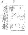
- 1 to 3 consists of a holder 2 for heating elements and a foot 3 which is designed as a bayonet mount.
- the hollow cylindrical foot 3 is formed in the axial extension centrally on the likewise essentially hollow cylindrical fixing 2.
- the definition 2 for the heating elements consists of a plate plate 4 which extends radially to the axis of the foot 3 and which is provided with two guide channels 5, 5a for the heating elements which run perpendicularly and symmetrically to the axis of the foot and intersect at right angles.
- the perpendicular to the Plate 5 standing outer wall 6 is broken through by the channels 5, 5a on opposite sides and connected to the side walls 7, 8 of the channels via curves 9.
- the guide channels 5, 5a each have a U-shaped cross section, the height and width of which correspond to the outer diameter of the heating elements to be inserted.
- the foot 3 of the holder 1 is provided on its lower edge 11 opposite the fixing 2 with a bottom 12 which has a gap 13 lying at right angles to one of the channels 5, 5a.
- slots 15, 16 are introduced into the foot wall 14, each rising from the gap 13 in helical lines with the same direction of rotation from slot starts 17, 18 to slot ends 19, 20 towards the plate plate 4.
- the slot ends 19, 20 are rotated radially by approximately 90 ° with respect to the slot beginnings 17, 18. Since the slots 15, 16 have the same pitch angle, on the one hand the slot beginnings 17, 18 and on the other hand the slot ends 19, 20 are flush with one another in the same radial planes in the foot wall 14. While the width 21 of the slots 15, 16 is less than the width of a mat rod to be inserted into the slots, the width 22 corresponds to the beginning of the slot and the slot end of the width of the mat bar.
- the carrier mat 24 can be arranged on the carrier mat 24 in a grid so that the heating elements 27 run parallel and in an arc between the holders 1.
- a holder 31 which consists of a fixing 32 and a foot 33.
- the fixing 32 corresponds to the fixing 2 of the holder 1 shown in FIGS. 1 to 5 and is therefore also provided with the same reference numerals
- the cylindrical foot 33 mounted centrally on the plate plate 4 has a plurality of radial ones distributed over the circumference of the foot and on the foot wall 34 projections 35 arranged in two radial planes. - Since these projections 35 are inclined towards the fixing 32, they act as barbs when the holder 31 according to FIG. 9 is inserted by axial pressing into a blind hole 36 which is in one on one
- the blanket 37 is placed on the insulating layer 38.
- the diameter of the blind hole 36 corresponds to that of the foot 33, so that the projections 35 engage in the insulating material and thus a tight fit of the holder 31 resting with the plate 4 on the insulating layer 38 is ensured, since between the raw ceiling 37 and the lower end of the blind hole 36 is still insulating material of the insulating layer 38, no thermal or acoustic bridge can arise between the bare ceiling 37 and the holder 31 provided with heating elements 39.
- the holders 31 provided with heating elements 39 are inserted into the blind holes 36 made in the grid-like manner in the insulating layer 38 such that the heating elements 39 are guided between the holders 31 in parallel and in an arc.
Landscapes
- Engineering & Computer Science (AREA)
- Physics & Mathematics (AREA)
- Mechanical Engineering (AREA)
- Thermal Sciences (AREA)
- Chemical & Material Sciences (AREA)
- Combustion & Propulsion (AREA)
- Architecture (AREA)
- General Engineering & Computer Science (AREA)
- Electromagnetism (AREA)
- Civil Engineering (AREA)
- Structural Engineering (AREA)
- Central Heating Systems (AREA)
- Floor Finish (AREA)
- Resistance Heating (AREA)
Applications Claiming Priority (2)
| Application Number | Priority Date | Filing Date | Title |
|---|---|---|---|
| DE3009419 | 1980-03-12 | ||
| DE19803009419 DE3009419A1 (de) | 1980-03-12 | 1980-03-12 | Rohrhalter |
Publications (1)
| Publication Number | Publication Date |
|---|---|
| EP0035722A1 true EP0035722A1 (de) | 1981-09-16 |
Family
ID=6096951
Family Applications (1)
| Application Number | Title | Priority Date | Filing Date |
|---|---|---|---|
| EP81101459A Withdrawn EP0035722A1 (de) | 1980-03-12 | 1981-02-28 | Rohrhalter |
Country Status (4)
| Country | Link |
|---|---|
| EP (1) | EP0035722A1 (es) |
| DE (1) | DE3009419A1 (es) |
| DK (1) | DK102981A (es) |
| ES (1) | ES500261A0 (es) |
Cited By (14)
| Publication number | Priority date | Publication date | Assignee | Title |
|---|---|---|---|---|
| EP0357151A3 (en) * | 1988-09-01 | 1990-10-24 | International Dome Systems | Method for manufacturing a building structure |
| WO1993011384A1 (en) * | 1991-11-28 | 1993-06-10 | Pipe Joist Clip Company Limited | Pipe retaining element |
| EP0961083A1 (fr) * | 1998-05-26 | 1999-12-01 | Rehau S.A. | Plaque de sol pour une installation de chauffage par le sol |
| AT510201B1 (de) * | 2010-07-20 | 2012-05-15 | Ke-Kelit Kunststoffwerk Gesellschaft M B H | Vorrichtung zum klimatisieren eines raumes |
| US10408469B2 (en) | 2014-08-18 | 2019-09-10 | Progress Profiles Spa | Method and apparatus for positioning heating elements |
| US10502434B2 (en) | 2016-04-01 | 2019-12-10 | Progress Profiles S.P.A. | Support for radiant covering and floor heating elements |
| NL2023088B1 (nl) * | 2019-05-08 | 2020-11-30 | Hajee B V | Vloerverwarmingssysteem en werkwijze voor het aanbrengen van vloerverwarming |
| US10859274B2 (en) | 2016-04-01 | 2020-12-08 | Progress Profiles S.P.A. | Support for radiant covering and floor heating elements |
| US11041638B2 (en) | 2009-08-28 | 2021-06-22 | Progress Profiles Spa | Method and apparatus for positioning heating elements |
| USD971449S1 (en) | 2016-04-13 | 2022-11-29 | Progress Profiles S.P.A. | Floor underlayment |
| USD1036243S1 (en) | 2020-10-09 | 2024-07-23 | Progress Profiles S.P.A. | Floor underlayment |
| USD1036242S1 (en) | 2020-04-22 | 2024-07-23 | Progress Profiles S.P.A. | Floor underlayment |
| USD1036979S1 (en) | 2020-04-06 | 2024-07-30 | Progress Profiles S.P.A. | Floor underlayment |
| USD1101979S1 (en) | 2023-02-07 | 2025-11-11 | Progress Profiles S.P.A. | Floor underlayment |
Families Citing this family (1)
| Publication number | Priority date | Publication date | Assignee | Title |
|---|---|---|---|---|
| DE3318694C2 (de) * | 1983-05-21 | 1985-09-12 | Franz-Josef 4434 Ochtrup Hagemann | Verfahren zum Herstellen einer aus modulartig zu verlegenden Platten bestehenden Bodenauflage |
Citations (1)
| Publication number | Priority date | Publication date | Assignee | Title |
|---|---|---|---|---|
| DE2807446A1 (de) * | 1978-02-22 | 1979-08-30 | Itw Ateco Gmbh | Loesbarer befestiger zum halten von bauelementen auf draht- oder stangenfoermigen traegern |
-
1980
- 1980-03-12 DE DE19803009419 patent/DE3009419A1/de not_active Withdrawn
-
1981
- 1981-02-28 EP EP81101459A patent/EP0035722A1/de not_active Withdrawn
- 1981-03-06 DK DK102981A patent/DK102981A/da not_active Application Discontinuation
- 1981-03-11 ES ES500261A patent/ES500261A0/es active Granted
Patent Citations (1)
| Publication number | Priority date | Publication date | Assignee | Title |
|---|---|---|---|---|
| DE2807446A1 (de) * | 1978-02-22 | 1979-08-30 | Itw Ateco Gmbh | Loesbarer befestiger zum halten von bauelementen auf draht- oder stangenfoermigen traegern |
Cited By (23)
| Publication number | Priority date | Publication date | Assignee | Title |
|---|---|---|---|---|
| EP0357151A3 (en) * | 1988-09-01 | 1990-10-24 | International Dome Systems | Method for manufacturing a building structure |
| WO1993011384A1 (en) * | 1991-11-28 | 1993-06-10 | Pipe Joist Clip Company Limited | Pipe retaining element |
| EP0961083A1 (fr) * | 1998-05-26 | 1999-12-01 | Rehau S.A. | Plaque de sol pour une installation de chauffage par le sol |
| FR2779165A1 (fr) * | 1998-05-26 | 1999-12-03 | Knauf Snc | Plaque a sol pour une installation de chauffage au sol |
| US11846432B2 (en) | 2009-08-28 | 2023-12-19 | Progress Profiles Spa | Method and apparatus for positioning heating elements |
| US11041638B2 (en) | 2009-08-28 | 2021-06-22 | Progress Profiles Spa | Method and apparatus for positioning heating elements |
| AT510201B1 (de) * | 2010-07-20 | 2012-05-15 | Ke-Kelit Kunststoffwerk Gesellschaft M B H | Vorrichtung zum klimatisieren eines raumes |
| US10712020B2 (en) | 2014-08-18 | 2020-07-14 | Progress Profiles Spa | Method and apparatus for positioning heating elements |
| US10739016B2 (en) | 2014-08-18 | 2020-08-11 | Progress Profiles Spa | Method and apparatus for positioning heating elements |
| US12044417B2 (en) | 2014-08-18 | 2024-07-23 | Progress Profiles Spa | Method and apparatus for positioning heating elements |
| US10408469B2 (en) | 2014-08-18 | 2019-09-10 | Progress Profiles Spa | Method and apparatus for positioning heating elements |
| US10502434B2 (en) | 2016-04-01 | 2019-12-10 | Progress Profiles S.P.A. | Support for radiant covering and floor heating elements |
| US10859274B2 (en) | 2016-04-01 | 2020-12-08 | Progress Profiles S.P.A. | Support for radiant covering and floor heating elements |
| US12560339B2 (en) | 2016-04-01 | 2026-02-24 | Progress Profiles S.P.A. | Support for radiant covering and floor heating elements |
| USD874028S1 (en) | 2016-04-13 | 2020-01-28 | Progress Profiles S.P.A. | Floor underlayment |
| USD971449S1 (en) | 2016-04-13 | 2022-11-29 | Progress Profiles S.P.A. | Floor underlayment |
| USD872901S1 (en) | 2016-04-13 | 2020-01-14 | Progress Profiles S.P.A. | Floor underlayment |
| USD880732S1 (en) | 2016-04-13 | 2020-04-07 | Progress Profiles S.P.A. | Floor underlayment |
| NL2023088B1 (nl) * | 2019-05-08 | 2020-11-30 | Hajee B V | Vloerverwarmingssysteem en werkwijze voor het aanbrengen van vloerverwarming |
| USD1036979S1 (en) | 2020-04-06 | 2024-07-30 | Progress Profiles S.P.A. | Floor underlayment |
| USD1036242S1 (en) | 2020-04-22 | 2024-07-23 | Progress Profiles S.P.A. | Floor underlayment |
| USD1036243S1 (en) | 2020-10-09 | 2024-07-23 | Progress Profiles S.P.A. | Floor underlayment |
| USD1101979S1 (en) | 2023-02-07 | 2025-11-11 | Progress Profiles S.P.A. | Floor underlayment |
Also Published As
| Publication number | Publication date |
|---|---|
| DE3009419A1 (de) | 1982-05-06 |
| ES8201720A1 (es) | 1981-12-16 |
| ES500261A0 (es) | 1981-12-16 |
| DK102981A (da) | 1981-09-13 |
Similar Documents
| Publication | Publication Date | Title |
|---|---|---|
| EP0035722A1 (de) | Rohrhalter | |
| DE3401015A1 (de) | Befestigungsvorrichtung fuer pfosten und verfahren zur einbettung der befestigungsvorrichtung in beton | |
| DE9320652U1 (de) | Rahmenelement und Einsatzelement für Ställe | |
| EP0388692B1 (de) | Isoliertes Kragplattenanschlusselement | |
| DE69313053T2 (de) | Bauelement | |
| DE3405682A1 (de) | Verlorene schalung | |
| DE2255086A1 (de) | Einrichtung zum aufstellen von betonwaenden | |
| EP0018597A1 (de) | Halterung, insbesondere zur Verlegung und Befestigung von Rohren von Fussbodenheizungen auf Fussböden | |
| EP0049431A2 (de) | Rasterdecke | |
| CH665672A5 (de) | Schalungsvorrichtung. | |
| WO2020160833A1 (de) | Montagesystem für die montage einer verankerungsvorrichtung und ein verfahren für die montage einer verankerungsvorrichtung an einer teilbaute aus beton | |
| EP0537727B1 (de) | Verbindungseinrichtung für Platten und/oder Bewehrungen einer Verbundschalung | |
| EP3546666A1 (de) | Holz-beton-verbindungsbausatz | |
| EP0994310A1 (de) | Rohrregister | |
| DE3108573A1 (de) | Kunststoffprofilleiste mit an der oberseite befestigten rohraufnahmeelementen zum verlegen und fixieren des heizungsrohres einer fussbodenheizung | |
| EP0040681A1 (de) | Vorrichtung zur Halterung von Heizungsrohren und/oder Bewehrungsgittern, insbesondere für Fussbodenheizungen | |
| DE3841572A1 (de) | Befestigungselement zum halten von fussbodenheizungsrohren an bewehrungsdraehten bzw. auflagegittern | |
| DE69413424T2 (de) | Gussform zum eingraben von rohren | |
| DE3502415A1 (de) | Einrichtung und verfahren zur herstellung von schalungseinheiten | |
| DE2930975A1 (de) | Abstandhalter | |
| DE3308473C2 (de) | Balken- oder Rippendecke | |
| AT213026B (de) | Aufhängevorrichtung für Unterdecken von Gebäuden | |
| EP0176815A2 (de) | Abstandhalter für Stahlbeton-Konstruktionen | |
| DE3111348A1 (de) | Vorrichtung zur halterung von heizungsrohren und/oder bewehrungsgittern, insbesondere fuer fussbodenheizungen | |
| DE29702121U1 (de) | Haltevorrichtung |
Legal Events
| Date | Code | Title | Description |
|---|---|---|---|
| PUAI | Public reference made under article 153(3) epc to a published international application that has entered the european phase |
Free format text: ORIGINAL CODE: 0009012 |
|
| AK | Designated contracting states |
Designated state(s): AT BE FR NL SE |
|
| 17P | Request for examination filed |
Effective date: 19811029 |
|
| STAA | Information on the status of an ep patent application or granted ep patent |
Free format text: STATUS: THE APPLICATION HAS BEEN WITHDRAWN |
|
| 18W | Application withdrawn |
Withdrawal date: 19830412 |
|
| RIN1 | Information on inventor provided before grant (corrected) |
Inventor name: HEGER, WOLFRAM HUBERTUS |