EP0035732B1 - Isolation thermique pour le domaine vouté du fond et/ou du couvercle d'un récipient sous pression - Google Patents
Isolation thermique pour le domaine vouté du fond et/ou du couvercle d'un récipient sous pression Download PDFInfo
- Publication number
- EP0035732B1 EP0035732B1 EP81101494A EP81101494A EP0035732B1 EP 0035732 B1 EP0035732 B1 EP 0035732B1 EP 81101494 A EP81101494 A EP 81101494A EP 81101494 A EP81101494 A EP 81101494A EP 0035732 B1 EP0035732 B1 EP 0035732B1
- Authority
- EP
- European Patent Office
- Prior art keywords
- thermal insulation
- pressure vessel
- pressure
- insulation cap
- cap
- Prior art date
- Legal status (The legal status is an assumption and is not a legal conclusion. Google has not performed a legal analysis and makes no representation as to the accuracy of the status listed.)
- Expired
Links
- 238000009413 insulation Methods 0.000 title claims abstract description 57
- 238000007789 sealing Methods 0.000 claims description 20
- 238000010438 heat treatment Methods 0.000 claims description 19
- 239000002184 metal Substances 0.000 claims description 8
- 239000011810 insulating material Substances 0.000 claims description 5
- 230000007704 transition Effects 0.000 claims description 3
- 230000002093 peripheral effect Effects 0.000 claims description 2
- 238000012360 testing method Methods 0.000 abstract description 10
- 238000005253 cladding Methods 0.000 description 5
- 230000008878 coupling Effects 0.000 description 3
- 238000010168 coupling process Methods 0.000 description 3
- 238000005859 coupling reaction Methods 0.000 description 3
- 239000002557 mineral fiber Substances 0.000 description 3
- 238000013102 re-test Methods 0.000 description 3
- XLYOFNOQVPJJNP-UHFFFAOYSA-N water Substances O XLYOFNOQVPJJNP-UHFFFAOYSA-N 0.000 description 3
- VYPSYNLAJGMNEJ-UHFFFAOYSA-N Silicium dioxide Chemical compound O=[Si]=O VYPSYNLAJGMNEJ-UHFFFAOYSA-N 0.000 description 2
- 229910000831 Steel Inorganic materials 0.000 description 2
- 238000010276 construction Methods 0.000 description 2
- 238000011161 development Methods 0.000 description 2
- 230000018109 developmental process Effects 0.000 description 2
- 239000002245 particle Substances 0.000 description 2
- 238000002360 preparation method Methods 0.000 description 2
- 230000001681 protective effect Effects 0.000 description 2
- 239000007921 spray Substances 0.000 description 2
- 239000010959 steel Substances 0.000 description 2
- 238000003466 welding Methods 0.000 description 2
- 241000191291 Abies alba Species 0.000 description 1
- 238000009835 boiling Methods 0.000 description 1
- 210000000078 claw Anatomy 0.000 description 1
- 230000007797 corrosion Effects 0.000 description 1
- 238000005260 corrosion Methods 0.000 description 1
- 239000011888 foil Substances 0.000 description 1
- 239000012774 insulation material Substances 0.000 description 1
- 230000013011 mating Effects 0.000 description 1
- 238000005259 measurement Methods 0.000 description 1
- 239000011490 mineral wool Substances 0.000 description 1
- 230000000149 penetrating effect Effects 0.000 description 1
- 230000005855 radiation Effects 0.000 description 1
- 230000035939 shock Effects 0.000 description 1
- 235000012239 silicon dioxide Nutrition 0.000 description 1
- 239000000377 silicon dioxide Substances 0.000 description 1
- 238000002604 ultrasonography Methods 0.000 description 1
Images


Classifications
-
- G—PHYSICS
- G21—NUCLEAR PHYSICS; NUCLEAR ENGINEERING
- G21C—NUCLEAR REACTORS
- G21C1/00—Reactor types
- G21C1/04—Thermal reactors ; Epithermal reactors
- G21C1/06—Heterogeneous reactors, i.e. in which fuel and moderator are separated
- G21C1/08—Heterogeneous reactors, i.e. in which fuel and moderator are separated moderator being highly pressurised, e.g. boiling water reactor, integral super-heat reactor, pressurised water reactor
- G21C1/09—Pressure regulating arrangements, i.e. pressurisers
-
- G—PHYSICS
- G21—NUCLEAR PHYSICS; NUCLEAR ENGINEERING
- G21C—NUCLEAR REACTORS
- G21C11/00—Shielding structurally associated with the reactor
- G21C11/08—Thermal shields; Thermal linings, i.e. for dissipating heat from gamma radiation which would otherwise heat an outer biological shield ; Thermal insulation
- G21C11/083—Thermal shields; Thermal linings, i.e. for dissipating heat from gamma radiation which would otherwise heat an outer biological shield ; Thermal insulation consisting of one or more metallic layers
-
- G—PHYSICS
- G21—NUCLEAR PHYSICS; NUCLEAR ENGINEERING
- G21C—NUCLEAR REACTORS
- G21C13/00—Pressure vessels; Containment vessels; Containment in general
- G21C13/02—Details
- G21C13/032—Joints between tubes and vessel walls, e.g. taking into account thermal stresses
- G21C13/036—Joints between tubes and vessel walls, e.g. taking into account thermal stresses the tube passing through the vessel wall, i.e. continuing on both sides of the wall
-
- G—PHYSICS
- G21—NUCLEAR PHYSICS; NUCLEAR ENGINEERING
- G21C—NUCLEAR REACTORS
- G21C17/00—Monitoring; Testing ; Maintaining
- G21C17/10—Structural combination of fuel element, control rod, reactor core, or moderator structure with sensitive instruments, e.g. for measuring radioactivity, strain
- G21C17/116—Passages or insulators, e.g. for electric cables
-
- Y—GENERAL TAGGING OF NEW TECHNOLOGICAL DEVELOPMENTS; GENERAL TAGGING OF CROSS-SECTIONAL TECHNOLOGIES SPANNING OVER SEVERAL SECTIONS OF THE IPC; TECHNICAL SUBJECTS COVERED BY FORMER USPC CROSS-REFERENCE ART COLLECTIONS [XRACs] AND DIGESTS
- Y02—TECHNOLOGIES OR APPLICATIONS FOR MITIGATION OR ADAPTATION AGAINST CLIMATE CHANGE
- Y02E—REDUCTION OF GREENHOUSE GAS [GHG] EMISSIONS, RELATED TO ENERGY GENERATION, TRANSMISSION OR DISTRIBUTION
- Y02E30/00—Energy generation of nuclear origin
- Y02E30/30—Nuclear fission reactors
Definitions
- the invention relates to thermal insulation for the curved floor and / or lid area of a pressure vessel according to the preamble of claim 1.
- the task is to design the thermal insulation of the type defined at the beginning and to provide it with such means that it can be removed and reassembled quickly and easily. This is not only important for the so-called zero measurement (before the nuclear reactor becomes critical), but in particular for the repeat tests during the shutdown of a nuclear power plant that has already been in operation, since radiation then appears on the pressure vessels to be inspected, which means that working on them Components only in protective suits and only for a relatively short time.
- One of the primary circuit components that has recently to be subjected to a repeat test in its nozzle area is the pressure holder, which has a base fitted with heating elements and corresponding heating element bushings, which has to be repeatedly tested at specified intervals.
- the invention is therefore based on the special task of creating a comfortable and quick to disassemble and reassemble thermal insulation for a pressure holder floor, which allows the repeat test to be carried out with only a short preparation time (exposing the nozzle lanes to be tested by removing the thermal insulation).
- the object is achieved with thermal insulation according to the preamble of claim 1 by the features specified in the characterizing part of claim 1. Further developments of the subject matter of the invention are described in the subclaims.
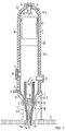
- the pressure holder 1 shown in Fig. 1 is a standing pressure vessel of essentially hollow cylindrical shape. It is composed of a cylindrical jacket 1a and an upper and a lower hemisphere 1b, 1 each.
- the lower floor has floor sockets 2 for gas and pressure-tight passage of the pressure-holding heating elements 3.
- a support claw 4 for a support 5 (not shown in more detail) can be seen somewhat above the lower floor, as well as a connection piece 6 welded into the pressure holder wall for the volume compensation line and a manhole 7 with manhole cover 7a.
- 11 is a protective shirt fastened within the pressure holder 1, which causes the upper part of the pressure holder 1 to be protected against thermal shock protected by cold water spray.
- the pressure holder 1 is enclosed by a thermal insulation designated as a whole by 12, which consists of individual cylindrical sections 12.1 and of the upper floor hood 12.2 and the lower floor hood 12.3.
- the shots 12.1 and the upper floor hood 12.2 can in turn be divided into individual segments.
- Each of the segments expediently consists of an insulating material based on mineral fibers or mineral wool, which is enclosed by metal foils, in particular austenitic sheet metal.
- the individual segments are easily de- and remonta in the areas that should be repeatable arranged and for this purpose in particular by means of tension locks (not shown) on the circumference of the pressure holder.
- the present invention now deals with the thermal insulation for the curved floor 1c of the pressure holder 1, which is penetrated in this area by a plurality of floor sockets 2 which run axially parallel to the pressure holder.
- the floor socket 2 and the heating rods 3 are only shown in simplified form in FIG. 1; in reality not only two but a plurality of floor sockets with corresponding individual heating elements are distributed over the area of the floor 1c c, which will be discussed further below.
- the rod-shaped electrical heating elements 3, which are provided with schematically indicated electrical connection lines 13 and protrude into the interior of the pressure holder 1, are, as mentioned, passed through the bottom connections 2 of the pressure holder in a pressure-tight and electrically insulated manner.
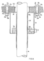
- the thermal insulation 12.3 is now designed as a one-piece thermal insulation hood which has a passage 41 for each floor socket 2.
- the thermal insulation hood 12.3 is centered on guide elements 15, 16 arranged axially parallel to the pressure holder and is axially displaceably supported in such a way that the thermal insulation hood 12.3 can be lowered from its largely convection-tight operating position to a mounting platform 17 shown in dashed lines, on which the nozzle lanes 18 des Pressure holder for the retest are exposed. After the repeat test has been carried out, the thermal insulation hood 12.3 can be raised from its parking position II back to the operating position I.
- gripping cables or pulley blocks (not shown) can be used, which are easy to operate manually or by means of small lifting motors.
- the mounting platform 17 is a metal grid construction which has a central opening 17a, through which the power supply cable 13 of the heating rods 3 and the central drainage line 15 of the pressure holder 1 are guided downward.
- the central drainage line 15 and at least one further vertical guide rod 16 are used to guide the thermal insulation hood 12.3 when lowering and lifting again, the thermal insulation hood 12.3 being able to slide in the axial direction on the drainage line 15 and the guide rod 16 by means of guide bushes not shown in FIG. 1.
- the cables 13 do not need to be removed when lowering the thermal insulation hood 12.3; rather, the hood is constructed, as will be explained in the following, in such a way that its sealing bushes, which comprise the heating rod bushings, slide over the cables.
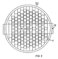
- FIG. 2 shows, as said, the top view of the lower calotte of the pressure holder with a plurality of passages 41 of the thermal insulation hood assigned to the floor sockets, with a centrally arranged bushing 19 for the central drainage line 15 (FIG. 1) and the vertical guide bushing 20 for the downwardly extending guide rod 16 (Fig. 1).
- FIG. 3 shows that the thermal insulation hood 12.3 is provided on its outer diameter with a sheet metal casing 21, which in the operating position I (FIG. 1) has sealing surfaces 21a (see FIG. 4) in largely convection-tight engagement with the transition and / or cylindrical area of the thermal insulation 12, 12.1 of the pressure holder 1 (see FIG. 1) can be brought.
- the sheet metal enclosure 21 also increases the stability of the hood 12.3 and its torsional rigidity.
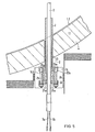
- FIG. 4 in connection with FIG. 5 shows in detail that the hood 12.3 has a passage for each floor socket.
- the largely convection-tight sealing of the hood 12.3 to the heating rod flanges 22 assigned to the connecting pieces 2 and the heating rods 3 takes place via sealing bushes 14.
- sealing bushes 14 will be mentioned, although it must also be said that in principle there is also a convection-tight passage another implementation element is conceivable.
- 1.1 denotes the wall of the pressure holder 1, 1.2 the austenitic inner cladding of this wall.
- the bottom sockets 2 are inserted and welded into through-bores 23 of this wall 1.1 which are parallel to one another.
- the floor sockets 2 are provided with a reinforced coupling flange 14.1, furthermore with a collar 22a which engages behind this flange and is pushed onto the neck of the floor socket 2 and which is provided with a ring of threaded bores for screwing in the expansion screws 24.
- the sealing disk 25 is a steel disc that is welded to the outer circumference of the heating element 3 in a sealing manner.
- 3a, 3b are the electrical lead wires which lead into the heating rod 3 to corresponding heating coils, not shown.
- the sealing sleeve 14 encompasses both the ring collar 22a and the cover 22 on their outer circumference.
- the outer diameter of the ring collar 22a is somewhat larger than that of the cover 22, so that the sealing sleeve 14 can be pushed over with a certain amount of play over the outer circumference of the cover 22 when the hood 12.3 is slid on, and then a sealing seat on the outer circumference of the ring collar 22a, i.e. a convection seal.
- the insulation hood 12.3 is preferably made of austenitic steel sheet, which is corrosion-resistant; it is made of corresponding disc-shaped parts 12.3a and cylindrical parts 12.3b welded together.
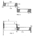
- the disk parts 12.3a are each arranged at a distance a from one another (see FIG. 6) and, with their peripheral walls 12.3b, form ring boxes in which the insulating material 26 is arranged and enclosed.
- a mineral fiber product is particularly suitable as insulation material 26. It has proven to be particularly advantageous if a special insulating material with a lower thermal conductivity than that of the still air is used, which is sold under the trademark "MINILEIT".
- the disk and cylinder parts 12.3a, 12.3b are provided with corresponding overhangs 12.4, which, cf. 6 and 7, overlap one another, the overlaps being spot welded.
- the sealing sleeves 14 are floatingly supported with their outer circumference on the inner circumference of cladding sheets 12.5, which limit the passage openings 41 of the hood 12.3.
- These cladding sheets 12.5 also have the above-mentioned projections 12.4 and are connected by means of them to the adjacent disk and cylinder parts of the hood 12.3 by means of spot welding.
- the floating bearing results from the elasticity of the cladding sheets 12.5 and their flanges 12.4.
- the sealing sleeve 14 can be fastened to the cladding sheets 12.5 by means of a few welding spots.
- the floating bearing is particularly advantageous because it allows slight tolerances to be compensated for when the hood 12.3 is put on, i.e. the cover 22, which is somewhat smaller in its outer circumference, fits in any case into the inner circumference of the sealing sleeve 14, which is thereby centered and then finds its seat on the annular collar 22a when pushed on further.
- FIG. 4 in connection with FIGS. 8 and 9 shows more clearly that the drainage line 15 running approximately in the longitudinal axis of the pressure holder 1 is encompassed by a bushing 27 arranged centrally on the hood 12.3.
- the hood 12.3 is provided with an anchor plate 28 which has a through opening 28a for the drainage line 15.
- the sleeve 27 is welded to the anchor plate 28 with a circumferential weld seam 27a (see also FIGS. 8 and 9).
- the latter is again with the hood 12.3, i.e. their central sheet metal disks 12.3a, by means of the corresponding through holes penetrating screw bolts 29, the latter in turn having a head 29a, a shaft 29b, washers 29c and the actual nut 29d.
- the bushing 27 has an inner sleeve part 30 which is provided with an annular collar 30a on its outer circumference.
- threaded holes 30b are cut in and distributed over the circumference, and the adjusting screws 31 are screwed into these from the outer circumference of the bushing 27.
- the anchor plate 28 is provided with serrations 28b on its outer circumference so that, cf. Fig. 3, the space for the sealing sleeves 14 remains free.
- the thermal insulation hood according to the invention is not only suitable for pressure holders and not only for pressure vessels, the nozzle field of which is arranged in the region of the lower bottom cap.
- the invention can also be used advantageously for other pressure vessels, e.g. Insert the reactor pressure vessel, in which the repeat lanes are arranged in the area of the upper cap. This is the case with nuclear reactor pressure vessels for pressurized water reactors, whereas with boiling water reactors, the control rod drives are generally guided through the bottom cap, that is, similar to the pressure holder shown.
Landscapes
- Engineering & Computer Science (AREA)
- Physics & Mathematics (AREA)
- Plasma & Fusion (AREA)
- General Engineering & Computer Science (AREA)
- High Energy & Nuclear Physics (AREA)
- General Health & Medical Sciences (AREA)
- Biomedical Technology (AREA)
- Health & Medical Sciences (AREA)
- Molecular Biology (AREA)
- Life Sciences & Earth Sciences (AREA)
- Filling Or Discharging Of Gas Storage Vessels (AREA)
- Pressure Vessels And Lids Thereof (AREA)
- Packages (AREA)
- Thermal Insulation (AREA)
- Inorganic Insulating Materials (AREA)
- Driving Mechanisms And Operating Circuits Of Arc-Extinguishing High-Tension Switches (AREA)
- Glass Compositions (AREA)
- Monitoring And Testing Of Nuclear Reactors (AREA)
- Thermotherapy And Cooling Therapy Devices (AREA)
Claims (6)
Priority Applications (1)
| Application Number | Priority Date | Filing Date | Title |
|---|---|---|---|
| AT81101494T ATE8824T1 (de) | 1980-03-10 | 1981-03-02 | Waermedaemmung fuer den gewoelbten boden- und/oder deckelbereich eines druckbehaelters. |
Applications Claiming Priority (2)
| Application Number | Priority Date | Filing Date | Title |
|---|---|---|---|
| DE19803009134 DE3009134A1 (de) | 1980-03-10 | 1980-03-10 | Waermedaemmung fuer den gewoelbten boden- und/oder deckelbereich eines druckbehaelters |
| DE3009134 | 1980-03-10 |
Publications (2)
| Publication Number | Publication Date |
|---|---|
| EP0035732A1 EP0035732A1 (fr) | 1981-09-16 |
| EP0035732B1 true EP0035732B1 (fr) | 1984-08-01 |
Family
ID=6096751
Family Applications (1)
| Application Number | Title | Priority Date | Filing Date |
|---|---|---|---|
| EP81101494A Expired EP0035732B1 (fr) | 1980-03-10 | 1981-03-02 | Isolation thermique pour le domaine vouté du fond et/ou du couvercle d'un récipient sous pression |
Country Status (9)
| Country | Link |
|---|---|
| US (1) | US4425963A (fr) |
| EP (1) | EP0035732B1 (fr) |
| JP (1) | JPS56145390A (fr) |
| AT (1) | ATE8824T1 (fr) |
| BR (1) | BR8101366A (fr) |
| CA (1) | CA1179612A (fr) |
| DE (2) | DE3009134A1 (fr) |
| ES (1) | ES500211A0 (fr) |
| YU (1) | YU60081A (fr) |
Families Citing this family (13)
| Publication number | Priority date | Publication date | Assignee | Title |
|---|---|---|---|---|
| US5094801A (en) * | 1990-01-22 | 1992-03-10 | The Babcock & Wilcox Company | Two piece pressurizer heater sleeve |
| US5091140A (en) * | 1990-01-22 | 1992-02-25 | The Babcock & Wilcox Company | Method of replacing a heater nozzle in a nuclear reactor pressurizer |
| US6258170B1 (en) | 1997-09-11 | 2001-07-10 | Applied Materials, Inc. | Vaporization and deposition apparatus |
| US6527865B1 (en) | 1997-09-11 | 2003-03-04 | Applied Materials, Inc. | Temperature controlled gas feedthrough |
| WO1999040588A1 (fr) * | 1998-02-03 | 1999-08-12 | Siemens Aktiengesellschaft | Accumulateur de pression et procede de mise a disposition d'un fluide sous pression |
| EP1124227B1 (fr) * | 2000-02-10 | 2007-07-04 | Sony Corporation | Tête de lecture optique, dispositif pour détecter une inclinaison, procédé pour détecter une inclinaison, et appareil de disque optique |
| US7112541B2 (en) * | 2004-05-06 | 2006-09-26 | Applied Materials, Inc. | In-situ oxide capping after CVD low k deposition |
| US7273823B2 (en) * | 2005-06-03 | 2007-09-25 | Applied Materials, Inc. | Situ oxide cap layer development |
| CN101504114B (zh) * | 2008-12-31 | 2012-10-10 | 江苏裕兴电器有限公司 | 高压可拆换型电加热器组件 |
| US8109159B1 (en) * | 2009-06-23 | 2012-02-07 | Turbine Technologies, Inc. | Instrumentation installation tool for a pressure vessel test rig |
| FR2967288B1 (fr) * | 2010-11-04 | 2015-07-17 | Electricite De France | Procede de remplissage en eau d'un circuit primaire d'un reacteur nucleaire, et dispositif de raccordement destine a la mise en oeuvre du procede |
| US9773574B2 (en) | 2013-11-04 | 2017-09-26 | The Regents Of The University Of California | Systems and methods for enhancing isolation of high-temperature reactor containments |
| CN114582529B (zh) * | 2022-02-16 | 2024-08-20 | 中国核动力研究设计院 | 基于大盘管蒸汽发生器的微型全自然循环压水反应堆系统 |
Family Cites Families (18)
| Publication number | Priority date | Publication date | Assignee | Title |
|---|---|---|---|---|
| GB846753A (en) * | 1957-06-24 | 1960-08-31 | Atomic Energy Authority Uk | Improvements in or relating to heat insulation devices |
| US2925934A (en) | 1957-11-26 | 1960-02-23 | Lox Equip | Support means for the movable end of a vessel |
| GB894407A (en) * | 1959-02-06 | 1962-04-18 | Babcock & Wilcox Ltd | Improvements in or relating to reactor pressure vessels |
| US3161266A (en) * | 1959-03-04 | 1964-12-15 | Babcock & Wilcox Ltd | Nuclear reactor insulation |
| GB1122452A (en) | 1965-11-02 | 1968-08-07 | Atomic Energy Authority Uk | Improvements relating to nuclear reactors |
| GB1247689A (en) | 1968-06-10 | 1971-09-29 | Atomic Energy Authority Uk | Improvements in or relating to removable covers for apertures in pressure vessels |
| GB1161670A (en) | 1968-07-17 | 1969-08-20 | Rolls Royce | Improvements in or relating to Pressure Vessels |
| US3836429A (en) | 1970-07-08 | 1974-09-17 | Westinghouse Electric Corp | Means for rapidly exposing the core of a nuclear reactor for refueling |
| US3744660A (en) | 1970-12-30 | 1973-07-10 | Combustion Eng | Shield for nuclear reactor vessel |
| US3713560A (en) | 1971-04-19 | 1973-01-30 | Gen Dynamics Corp | Spaced wall container |
| DE2259941A1 (de) | 1971-12-10 | 1973-06-14 | Nuclear Power Group Ltd | Druckgefaess mit thermischer isolation |
| GB1491204A (en) * | 1973-10-31 | 1977-11-09 | Nuclear Power Group Ltd | Thermal insulation |
| GB1529811A (en) * | 1975-06-20 | 1978-10-25 | Atomic Energy Authority Uk | Liquid metal cooled nuclear reactor constructions |
| DE2544054A1 (de) | 1975-10-02 | 1977-04-07 | Interatom | Rotationssymmetrischer behaelter mit einer isolierstoffhuelle |
| FR2329058A1 (fr) | 1975-10-21 | 1977-05-20 | Westinghouse Electric Corp | Pressuriseur comportant des thermoplongeurs tubulaires rectilignes pour reacteurs nucleaires |
| FR2330122A1 (fr) * | 1975-10-28 | 1977-05-27 | Commissariat Energie Atomique | Dispositif de solidarisation du couvercle de fermeture et de la structure interne superieure d'un reacteur nucleaire |
| DE2709914C2 (de) * | 1977-03-08 | 1986-10-09 | INTERATOM GmbH, 5060 Bergisch Gladbach | Flüssigmetallgekühlter Kernreaktor mit Einrichtungen zur Verhinderung der Konvektion von Metalldämpfen |
| US4156492A (en) | 1977-06-27 | 1979-05-29 | Lox Equipment Company | Vessel support apparatus |
-
1980
- 1980-03-10 DE DE19803009134 patent/DE3009134A1/de not_active Withdrawn
-
1981
- 1981-03-02 EP EP81101494A patent/EP0035732B1/fr not_active Expired
- 1981-03-02 DE DE8181101494T patent/DE3165155D1/de not_active Expired
- 1981-03-02 AT AT81101494T patent/ATE8824T1/de not_active IP Right Cessation
- 1981-03-09 ES ES500211A patent/ES500211A0/es active Granted
- 1981-03-09 CA CA000372537A patent/CA1179612A/fr not_active Expired
- 1981-03-09 YU YU00600/81A patent/YU60081A/xx unknown
- 1981-03-09 US US06/241,944 patent/US4425963A/en not_active Expired - Fee Related
- 1981-03-09 BR BR8101366A patent/BR8101366A/pt unknown
- 1981-03-09 JP JP3372181A patent/JPS56145390A/ja active Pending
Also Published As
| Publication number | Publication date |
|---|---|
| US4425963A (en) | 1984-01-17 |
| ATE8824T1 (de) | 1984-08-15 |
| DE3165155D1 (en) | 1984-09-06 |
| BR8101366A (pt) | 1981-09-15 |
| DE3009134A1 (de) | 1981-10-15 |
| CA1179612A (fr) | 1984-12-18 |
| EP0035732A1 (fr) | 1981-09-16 |
| JPS56145390A (en) | 1981-11-12 |
| YU60081A (en) | 1983-10-31 |
| ES8507674A1 (es) | 1985-09-01 |
| ES500211A0 (es) | 1985-09-01 |
Similar Documents
| Publication | Publication Date | Title |
|---|---|---|
| DE2301730A1 (de) | Pruefeinrichtung zum feststellen schadhafter brennstaebe in einem kernreaktor | |
| EP0035732A1 (fr) | Isolation thermique pour le domaine vouté du fond et/ou du couvercle d'un récipient sous pression | |
| DE68903247T2 (de) | Vorrichtung zum messen von parametern in der spaltzone eines im betrieb befindlichen kernreaktors. | |
| DE2832122A1 (de) | Messlanze fuer siedewasserkernreaktoren | |
| EP0137077B1 (fr) | Procédé et dispostif de localisation de chemises défectueuses de barreaux combustibles des réacteurs nucléaires refroidis par eau | |
| EP0629309B1 (fr) | Dispositif de prevention de defaillance due a la mise en surpression de la cuve sous pression d'un reacteur nucleaire | |
| EP0500656A1 (fr) | Reacteur nucleaire refroidi par metal liquide | |
| CH689240A5 (de) | Kernrohr- und Tragplattenbaueinheit fuer Druckwasserkernreaktor. | |
| DE2854155A1 (de) | Gasgekuehlter hochtemperaturreaktor mit einer mit gasdurchlaessen versehenen tragkonstruktion | |
| DE2644261A1 (de) | Kernreaktor | |
| DE69703063T2 (de) | Druckgefässbodendurchdringung | |
| DE2758192A1 (de) | Druckfeste heizstabdurchfuehrung fuer ein fluessiges, verdampfbares medium enthaltende druckbehaelter, vorzugsweise fuer druckhalter von kernreaktoranlagen | |
| DE1564162A1 (de) | Vorrichtung zum Abziehen der Waerme aus einem Kernreaktor | |
| DE2535355A1 (de) | Verschlussanordnung in einem gasgekuehlten kernreaktorsystem | |
| DE3027508C2 (fr) | ||
| DE3027506C2 (fr) | ||
| DE2225409C2 (de) | Vorrichtung zur seitlichen Abstützung eines Zylinderförmigen Behälters | |
| DE1489857B2 (de) | Zufuhroeffnung fuer einen atomkernreaktor | |
| DE3138907C1 (de) | Notkühlsystem für den Kern eines Reaktordruckbehälters | |
| CH661999A5 (de) | Kernreaktor. | |
| DE3042629A1 (de) | Mehrteiliger schutzmantel | |
| DE2722508C2 (de) | Kernreaktoranlage mit einem gasgekühlten Hochtemperaturkernreaktor | |
| DE3932223C2 (fr) | ||
| DE2224579A1 (de) | Schutzgefaess fuer druckbehaelter von kernreaktoren | |
| EP0835511A1 (fr) | Reacteur nucleaire a refroidissement du cour en fusion dans la chambre de propagation |
Legal Events
| Date | Code | Title | Description |
|---|---|---|---|
| PUAI | Public reference made under article 153(3) epc to a published international application that has entered the european phase |
Free format text: ORIGINAL CODE: 0009012 |
|
| AK | Designated contracting states |
Designated state(s): AT BE CH DE FR GB IT LU NL SE |
|
| 17P | Request for examination filed |
Effective date: 19810914 |
|
| ITF | It: translation for a ep patent filed | ||
| GRAA | (expected) grant |
Free format text: ORIGINAL CODE: 0009210 |
|
| AK | Designated contracting states |
Designated state(s): AT BE CH DE FR GB IT LI LU NL SE |
|
| REF | Corresponds to: |
Ref document number: 8824 Country of ref document: AT Date of ref document: 19840815 Kind code of ref document: T |
|
| REF | Corresponds to: |
Ref document number: 3165155 Country of ref document: DE Date of ref document: 19840906 |
|
| ET | Fr: translation filed | ||
| PGFP | Annual fee paid to national office [announced via postgrant information from national office to epo] |
Ref country code: AT Payment date: 19850227 Year of fee payment: 5 |
|
| PG25 | Lapsed in a contracting state [announced via postgrant information from national office to epo] |
Ref country code: LU Free format text: LAPSE BECAUSE OF NON-PAYMENT OF DUE FEES Effective date: 19850331 |
|
| PGFP | Annual fee paid to national office [announced via postgrant information from national office to epo] |
Ref country code: NL Payment date: 19850331 Year of fee payment: 5 |
|
| PLBE | No opposition filed within time limit |
Free format text: ORIGINAL CODE: 0009261 |
|
| STAA | Information on the status of an ep patent application or granted ep patent |
Free format text: STATUS: NO OPPOSITION FILED WITHIN TIME LIMIT |
|
| 26N | No opposition filed | ||
| PG25 | Lapsed in a contracting state [announced via postgrant information from national office to epo] |
Ref country code: AT Effective date: 19860302 |
|
| PG25 | Lapsed in a contracting state [announced via postgrant information from national office to epo] |
Ref country code: SE Effective date: 19860303 |
|
| PG25 | Lapsed in a contracting state [announced via postgrant information from national office to epo] |
Ref country code: LI Effective date: 19860331 Ref country code: CH Effective date: 19860331 Ref country code: BE Effective date: 19860331 |
|
| BERE | Be: lapsed |
Owner name: GRUNZWEIG + HARTMANN MONTAGE G.M.B.H. Effective date: 19860331 Owner name: KRAFTWERK UNION A.G. Effective date: 19860331 |
|
| PG25 | Lapsed in a contracting state [announced via postgrant information from national office to epo] |
Ref country code: NL Effective date: 19861001 |
|
| GBPC | Gb: european patent ceased through non-payment of renewal fee | ||
| PG25 | Lapsed in a contracting state [announced via postgrant information from national office to epo] |
Ref country code: FR Free format text: LAPSE BECAUSE OF NON-PAYMENT OF DUE FEES Effective date: 19861128 |
|
| REG | Reference to a national code |
Ref country code: CH Ref legal event code: PL |
|
| PG25 | Lapsed in a contracting state [announced via postgrant information from national office to epo] |
Ref country code: DE Effective date: 19861202 |
|
| NLV4 | Nl: lapsed or anulled due to non-payment of the annual fee | ||
| REG | Reference to a national code |
Ref country code: FR Ref legal event code: ST |
|
| PG25 | Lapsed in a contracting state [announced via postgrant information from national office to epo] |
Ref country code: GB Effective date: 19881118 |
|
| EUG | Se: european patent has lapsed |
Ref document number: 81101494.3 Effective date: 19870223 |