EP0035741B1 - Dispositif pour imprimer en plusieurs couleurs une bande en matière thermoplastique - Google Patents
Dispositif pour imprimer en plusieurs couleurs une bande en matière thermoplastique Download PDFInfo
- Publication number
- EP0035741B1 EP0035741B1 EP81101533A EP81101533A EP0035741B1 EP 0035741 B1 EP0035741 B1 EP 0035741B1 EP 81101533 A EP81101533 A EP 81101533A EP 81101533 A EP81101533 A EP 81101533A EP 0035741 B1 EP0035741 B1 EP 0035741B1
- Authority
- EP
- European Patent Office
- Prior art keywords
- cooling surface
- drying apparatus
- printing
- disposed
- cooling
- Prior art date
- Legal status (The legal status is an assumption and is not a legal conclusion. Google has not performed a legal analysis and makes no representation as to the accuracy of the status listed.)
- Expired
Links
Images
Classifications
-
- B—PERFORMING OPERATIONS; TRANSPORTING
- B41—PRINTING; LINING MACHINES; TYPEWRITERS; STAMPS
- B41F—PRINTING MACHINES OR PRESSES
- B41F23/00—Devices for treating the surfaces of sheets, webs, or other articles in connection with printing
- B41F23/04—Devices for treating the surfaces of sheets, webs, or other articles in connection with printing by heat drying, by cooling, by applying powders
- B41F23/0483—Drying combined with cooling
-
- B—PERFORMING OPERATIONS; TRANSPORTING
- B41—PRINTING; LINING MACHINES; TYPEWRITERS; STAMPS
- B41F—PRINTING MACHINES OR PRESSES
- B41F23/00—Devices for treating the surfaces of sheets, webs, or other articles in connection with printing
- B41F23/04—Devices for treating the surfaces of sheets, webs, or other articles in connection with printing by heat drying, by cooling, by applying powders
- B41F23/0403—Drying webs
- B41F23/0423—Drying webs by convection
- B41F23/0426—Drying webs by convection using heated air
Definitions
- the invention relates to a device for multicolor printing of thermoplastic film webs with a plurality of printing units connected in series and at least one drying device arranged between adjacent printing units, in which the freshly printed ink is dried by supplying air.
- the precision of the repeat is essential for multi-color printing of thermoplastic film webs, i.e. the exact coverage of the printed images that are transferred from the corresponding printing units, in particular printing rollers, to the film web.
- the film web itself is the cause of malfunctions. If the film web has been produced with a drawing calender, the web always has a thickness profile as a result of the rolling out, which is formed in accordance with the deflection and the roll shape. This thickness profile multiplies when rolled up into a roll. This results in differences in the diameter of the wrapping bale, which make printing or repeating difficult because of the inevitable stretching of the film web.
- These faults are prevented by feeding the thermoplastic film web to a heating and cooling cylinder combination before printing.
- the film web which is pressed onto a heating cylinder with a rubber roller, is heated and then cooled via a downstream cooling cylinder.
- the leveled film is then fed to the printing device.
- Paper formats are individual sections of paper that are passed through the known device and are also guided over a cooling roller.
- thermoplastic film webs the liquid content of the applied printing ink has no local or overall effect on the dimensions of the film web.
- heat treatment is critical, in particular in combination with a state of tension, which is generated, for example, by the thermoplastic film web being guided over a plurality of rolls or rollers or the like, the peripheral speeds of which are not exactly matched to one another.
- the invention has recognized that in the case of multicolored printing on film webs, the cause of the faults described must be sought primarily in the area of the drying devices, because in the area of the drying devices air is blown onto the printed side of the film web at room temperature or at a higher temperature in order to print the freshly printed Drying colors.
- the film also heats up and a shrinking process occurs in which the cross section of the film approximates the original thickness profile.
- the object of the invention is to improve compliance with the repeat in multicolor printing of thermoplastic film webs.
- each drying device has a sliding table arranged in the straight guide plane of the film web with a cooling surface for the non-printed side of the film web, and in that the drying air is blown in the direction of the cooling surface.
- the film web is to be guided over a straight guide plane, which means that the cooling surface of the sliding table is also flat and that the film web is guided parallel to it over the cooling surface.
- Multi-color printing of thermoplastic film webs uses a large number of printing cylinders, each with a different diameter. The diameter of a printing cylinder is determined by the design. If other patterns are to be printed in a different repeat using the same device, the printing cylinders are replaced. However, the new printing cylinders have a different diameter and, accordingly, a different peripheral speed because the drives of the printing cylinders cannot be controlled so precisely that a peripheral speed that is the same for all printing cylinders can be used.
- the drying device in the device according to the invention has a flat cooling surface, one avoids the difficulty of adapting cooling cylinders, as they are known in principle, with regard to their rotational speed or peripheral speed to the peripheral speed predetermined by the pressure cylinders present.
- thermoplastic film web guided over it passes without any force, so that the film web is not elongated when sliding over the cooling surface.
- an extremely thin air separation layer is formed between the flat cooling surface and the thermoplastic film web guided over it, on which the film floats like an air cushion, but which nevertheless still allows cooling. This air cushion is not reduced by the drying air blown against the cooling plate.
- thermoplastic film web when it overflows over the flat cooling surface serves to stabilize the thermoplastic film web. Since heating of the film web is neither necessary in the area of the preceding printing unit nor by means of drying air, the film web is brought into a state by the cooling effect to that extent, which makes it more resistant for processing in the next printing unit. This essentially means an increase in the resistance to longitudinal stresses that try to stretch the film web in the longitudinal direction. However, if such a longitudinal expansion is suppressed, the repeat can be set exactly.
- the sliding table expediently has coolant channels.
- These coolant channels can be formed by profile sheets arranged on the back of the sliding table and excluded from a cooling system with a heat exchanger and circulation pump. Other arrangements and configurations of the coolant channels are possible.
- An embodiment which is advantageous from a functional point of view is characterized in that a plurality of nozzles for supplying dry air are arranged opposite the cooling surface. Then the impulse of the air jets can also be used to press the film web against the cooling surface or the sliding table.
- the impulses of the air jets are usually so large that the film web is pressed against the cooling surface even when the cooling surface is directed downwards and the nozzles are arranged below it. As a result, the function of the drying device is largely independent of its respective spatial arrangement.
- the drying device with the cooling surface can be arranged essentially horizontally or at an angle to the horizontal or essentially vertically.
- a preferred embodiment is characterized by two drying devices arranged next to one another and connected in series, through which the film web is first guided upwards and then downwards again, or vice versa, before it runs into the next printing unit.
- the distance between the printing units can be kept short and at the same time the path of the film web available for drying can be increased.
- the drying device can also have a plurality of cooling surfaces arranged in different levels, in particular a vertical and then a horizontal cooling surface.
- each drying device in a housing, one wall of which forms the cooling surface.
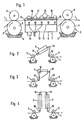
- the device shown in the figure is used for multi-color printing of thermoplastic film webs 1 with a plurality of printing units connected in series, of which only two printing units 2, 3 are shown in the drawing.
- the printing units 2, 3 are constructed identically, so that it is sufficient to describe only one printing unit.
- Each printing unit has an ink tray 4, in which a printing roller 5 is partially immersed.
- the pressure roller 5 has a drive, not shown.
- Each pressure roller 5 is assigned a press roller 6, which is arranged above the pressure roller 5 in the exemplary embodiment shown.
- the film web 1 is drawn into the nip between the printing roller 6 and printed on it. After printing, the film web 1 arrives in a drying device 7, which is enclosed by a housing 8, which has an inlet slot 9 on one side and an outlet slot 10 for the film web 1 on the opposite side.
- the housing 8 is box-shaped and has an essentially horizontal partition 11 with a plurality of nozzles 12 arranged therein.
- an inlet connection 14 for the supply of air with room temperature or also at a higher temperature.
- the supplied air is blown through the nozzles 12 onto the currently printed side of the film web 1 and is intended to dry the freshly printed ink. Used air is drawn off via an outlet connection (not shown).
- the upper wall of the housing 8 is designed as a cooled sliding table 15.
- the sliding table 15 has a cooling surface 16 directed downwards, against which the film web is pressed with its unprinted side under the angle of the air jets.
- a plurality of profiled sheets 17 are fastened, which form cooling channels 18 which connect to a cooling system (not shown) stem with heat exchanger and circulation pump are connected.
- the drying device 7 can be arranged not only with a horizontal cooling surface as in FIG. 1 but also with a cooling surface inclined to the horizontal (FIG. 2).
- a cooling surface inclined to the horizontal FIG. 2
- the drying device 7 can also be arranged vertically, as shown in FIG. 4. In this case, the embodiment shown in FIG.
Landscapes
- Engineering & Computer Science (AREA)
- Mechanical Engineering (AREA)
- Supply, Installation And Extraction Of Printed Sheets Or Plates (AREA)
- Coloring (AREA)
- Paper (AREA)
- Manufacturing Of Printed Wiring (AREA)
Claims (12)
Priority Applications (1)
| Application Number | Priority Date | Filing Date | Title |
|---|---|---|---|
| AT81101533T ATE7124T1 (de) | 1980-03-07 | 1981-03-04 | Vorrichtung zum mehrfarbigen bedrucken thermoplastischer folienbahnen. |
Applications Claiming Priority (2)
| Application Number | Priority Date | Filing Date | Title |
|---|---|---|---|
| DE3008703 | 1980-03-07 | ||
| DE19803008703 DE3008703A1 (de) | 1980-03-07 | 1980-03-07 | Vorrichtung zum mehrfarbingen bedrucken thermoplastischer folienbahnen |
Publications (2)
| Publication Number | Publication Date |
|---|---|
| EP0035741A1 EP0035741A1 (fr) | 1981-09-16 |
| EP0035741B1 true EP0035741B1 (fr) | 1984-04-18 |
Family
ID=6096487
Family Applications (1)
| Application Number | Title | Priority Date | Filing Date |
|---|---|---|---|
| EP81101533A Expired EP0035741B1 (fr) | 1980-03-07 | 1981-03-04 | Dispositif pour imprimer en plusieurs couleurs une bande en matière thermoplastique |
Country Status (3)
| Country | Link |
|---|---|
| EP (1) | EP0035741B1 (fr) |
| AT (1) | ATE7124T1 (fr) |
| DE (2) | DE3008703A1 (fr) |
Cited By (3)
| Publication number | Priority date | Publication date | Assignee | Title |
|---|---|---|---|---|
| DE19521442A1 (de) * | 1994-11-17 | 1996-05-30 | Lts Trocknungsverfahren Gmbh | Leiteinrichtung für bedruckte Bogen und/oder Bahnen in Trocknersystemen |
| DE29714455U1 (de) * | 1997-08-13 | 1997-10-09 | MAN Roland Druckmaschinen AG, 63075 Offenbach | Trocknereinrichtung für Bedruckstoffe in einer Verarbeitungsmaschine |
| DE19651406C1 (de) * | 1996-12-11 | 1998-06-10 | Roland Man Druckmasch | Trocknereinheit in einer Druckmaschine |
Families Citing this family (5)
| Publication number | Priority date | Publication date | Assignee | Title |
|---|---|---|---|---|
| FR2631584B1 (fr) * | 1988-05-18 | 1991-01-18 | Buy Stephane | Procede et equipements d'impression serigraphique pour composants metalliques d'objets sensibles a la chaleur |
| DE59402139D1 (de) * | 1993-12-16 | 1997-04-24 | Sebald U E | Trockenvorrichtung |
| DE19829383A1 (de) * | 1998-07-01 | 2000-01-05 | Koenig & Bauer Ag | Leiteinrichtung in Druckmaschinen |
| JP2009073011A (ja) * | 2007-09-20 | 2009-04-09 | Seiko Epson Corp | 液体噴射装置 |
| EP2047991A3 (fr) * | 2007-10-11 | 2011-11-16 | manroland AG | Dispositif de séchage à air thermique et procédé destiné à sécher une matière d'impression |
Citations (7)
| Publication number | Priority date | Publication date | Assignee | Title |
|---|---|---|---|---|
| FR675391A (fr) * | 1928-05-19 | 1930-02-10 | Procédé de séchage d'impressions polychromes | |
| DE494113C (de) * | 1927-07-22 | 1930-03-19 | Edwin Nagelstein Dipl Ing | Verfahren und Vorrichtung zum Trocknen der bedruckten Papierbahn bei Druckmaschinen,insbesondere Rotationstiefdruckmaschinen |
| DE622730C (de) * | 1930-04-30 | 1935-12-05 | Kadus Werk G M B H | Vorrichtung zum Trocknen von mit Tiefdruckfarben bedruckten Papier- oder Stoffbahnenmittels kalter Blasluft |
| US2268988A (en) * | 1939-08-08 | 1942-01-06 | Interchem Corp | Method and apparatus for drying printing ink |
| US2268985A (en) * | 1937-12-29 | 1942-01-06 | Interchem Corp | Method and apparatus for drying printing ink |
| FR951972A (fr) * | 1945-03-27 | 1949-11-07 | Lampes Sa | Procédé de séchage rapide par rayonnement infra-rouge |
| GB744343A (en) * | 1952-11-04 | 1956-02-01 | Svenska Vaxduks Aktiebolaget | Improved apparatus for treating webs of thermoplastic material |
Family Cites Families (1)
| Publication number | Priority date | Publication date | Assignee | Title |
|---|---|---|---|---|
| CH480175A (de) * | 1969-04-21 | 1969-10-31 | De La Rue Giori Sa | Mehrfarben-Stahlstichdruckmaschine für Bogen, insbesondere für Wertscheine |
-
1980
- 1980-03-07 DE DE19803008703 patent/DE3008703A1/de not_active Withdrawn
-
1981
- 1981-03-04 DE DE8181101533T patent/DE3163152D1/de not_active Expired
- 1981-03-04 EP EP81101533A patent/EP0035741B1/fr not_active Expired
- 1981-03-04 AT AT81101533T patent/ATE7124T1/de not_active IP Right Cessation
Patent Citations (7)
| Publication number | Priority date | Publication date | Assignee | Title |
|---|---|---|---|---|
| DE494113C (de) * | 1927-07-22 | 1930-03-19 | Edwin Nagelstein Dipl Ing | Verfahren und Vorrichtung zum Trocknen der bedruckten Papierbahn bei Druckmaschinen,insbesondere Rotationstiefdruckmaschinen |
| FR675391A (fr) * | 1928-05-19 | 1930-02-10 | Procédé de séchage d'impressions polychromes | |
| DE622730C (de) * | 1930-04-30 | 1935-12-05 | Kadus Werk G M B H | Vorrichtung zum Trocknen von mit Tiefdruckfarben bedruckten Papier- oder Stoffbahnenmittels kalter Blasluft |
| US2268985A (en) * | 1937-12-29 | 1942-01-06 | Interchem Corp | Method and apparatus for drying printing ink |
| US2268988A (en) * | 1939-08-08 | 1942-01-06 | Interchem Corp | Method and apparatus for drying printing ink |
| FR951972A (fr) * | 1945-03-27 | 1949-11-07 | Lampes Sa | Procédé de séchage rapide par rayonnement infra-rouge |
| GB744343A (en) * | 1952-11-04 | 1956-02-01 | Svenska Vaxduks Aktiebolaget | Improved apparatus for treating webs of thermoplastic material |
Cited By (3)
| Publication number | Priority date | Publication date | Assignee | Title |
|---|---|---|---|---|
| DE19521442A1 (de) * | 1994-11-17 | 1996-05-30 | Lts Trocknungsverfahren Gmbh | Leiteinrichtung für bedruckte Bogen und/oder Bahnen in Trocknersystemen |
| DE19651406C1 (de) * | 1996-12-11 | 1998-06-10 | Roland Man Druckmasch | Trocknereinheit in einer Druckmaschine |
| DE29714455U1 (de) * | 1997-08-13 | 1997-10-09 | MAN Roland Druckmaschinen AG, 63075 Offenbach | Trocknereinrichtung für Bedruckstoffe in einer Verarbeitungsmaschine |
Also Published As
| Publication number | Publication date |
|---|---|
| EP0035741A1 (fr) | 1981-09-16 |
| ATE7124T1 (de) | 1984-05-15 |
| DE3008703A1 (de) | 1981-09-24 |
| DE3163152D1 (en) | 1984-05-24 |
Similar Documents
| Publication | Publication Date | Title |
|---|---|---|
| DE69801184T2 (de) | Tiefdruckmaschine | |
| DE102008043767A1 (de) | Druckmaschine und Verfahren zur Handhabung einer durch die Druckmaschine geführten Bahn | |
| DE3905400C2 (fr) | ||
| DE4327646C2 (de) | Breiten-Einstellverfahren für eine Papierbahn sowie damit ausgerüstete lithographische Rotationspresse | |
| DE3128430C2 (de) | Rotationsdruckmaschine mit einem an einen Trockner anschließenden Kühlwerk | |
| EP0035741B1 (fr) | Dispositif pour imprimer en plusieurs couleurs une bande en matière thermoplastique | |
| DE19916257B4 (de) | Mehrfarben-Druckmaschine zum wahlweisen Bedrucken von einzelnen Bahnen oder von zwei Bahnen | |
| DE2012553A1 (de) | Mehrfarben-Stahlstichdruckmaschine für Bogen, insbesondere für Wertscheine | |
| CH687917A5 (de) | Vorrichtung zur Papierfuehrung bei Rollenrotationsdruckmaschinen. | |
| CH695765A5 (de) | Neun-Zylinder-Satellitendruckeinheit. | |
| DE407369C (de) | Gummidruckmaschine zum fortlaufenden Bedrucken von Papier- oder Stoffbahnen mit zwei Gegendruckzylindern | |
| EP0773104A1 (fr) | Procédé pour l'ennoblissement et l'impression d'une bande et machine d'impression pour la mise en oeuvre de ce procédé | |
| DE3429079C3 (de) | Rollenrotations-Offsetdruckmaschine | |
| DE10248249B4 (de) | Trockner für eine Materialbahn | |
| DE4324337C2 (de) | Wiederbefeuchtungseinrichtung für eine bedruckte Papierbahn | |
| DE3114406A1 (de) | Druckmaschine zum bedrucken einer folienbahn aus kunststoff | |
| DE3103421A1 (de) | Siebdruckmaschine | |
| DE2942689C2 (de) | Vorrichtung zum Übertragen von Farbe in einem Farbwerk einer Offset-Rotationsdruckmaschine | |
| DE2150986C3 (de) | Vorrichtung zur Beeinflussung der Durchwölbung einer Druckträgerbahn zwischen mindestens zwei Druckwerken einer Rollenrotationsdruckmaschine | |
| DE4228611A1 (de) | Papierführung bei Rollenrotationsdruckmaschinen | |
| DE19802739A1 (de) | Kühlvorrichtung in einem Falzaufbau und Kühlverfahren | |
| DE102022121373B3 (de) | Bahn-Bogen-Druckmaschine | |
| DE8006179U1 (de) | Vorrichtung zum mehrfarbigen bedrucken thermoplastischer folienbahnen | |
| AT203517B (de) | Verfahren zum Hindurchführen einer Metallbahn durch eine Druckmaschine und Druckmaschine zur Durchführung des Verfahrens | |
| DE102008042085B4 (de) | Verfahren und Vorrichtung zum Führen von Bahnen in einer Rollenrotationsdruckmaschine |
Legal Events
| Date | Code | Title | Description |
|---|---|---|---|
| PUAI | Public reference made under article 153(3) epc to a published international application that has entered the european phase |
Free format text: ORIGINAL CODE: 0009012 |
|
| AK | Designated contracting states |
Designated state(s): AT BE CH DE FR GB IT LU NL SE |
|
| 17P | Request for examination filed |
Effective date: 19810922 |
|
| ITF | It: translation for a ep patent filed | ||
| GRAA | (expected) grant |
Free format text: ORIGINAL CODE: 0009210 |
|
| AK | Designated contracting states |
Designated state(s): AT BE CH DE FR GB IT LI LU NL SE |
|
| PG25 | Lapsed in a contracting state [announced via postgrant information from national office to epo] |
Ref country code: SE Effective date: 19840418 Ref country code: NL Effective date: 19840418 |
|
| REF | Corresponds to: |
Ref document number: 7124 Country of ref document: AT Date of ref document: 19840515 Kind code of ref document: T |
|
| REF | Corresponds to: |
Ref document number: 3163152 Country of ref document: DE Date of ref document: 19840524 |
|
| ET | Fr: translation filed | ||
| NLV1 | Nl: lapsed or annulled due to failure to fulfill the requirements of art. 29p and 29m of the patents act | ||
| PLBE | No opposition filed within time limit |
Free format text: ORIGINAL CODE: 0009261 |
|
| STAA | Information on the status of an ep patent application or granted ep patent |
Free format text: STATUS: NO OPPOSITION FILED WITHIN TIME LIMIT |
|
| PG25 | Lapsed in a contracting state [announced via postgrant information from national office to epo] |
Ref country code: AT Effective date: 19850304 |
|
| PG25 | Lapsed in a contracting state [announced via postgrant information from national office to epo] |
Ref country code: LU Free format text: LAPSE BECAUSE OF NON-PAYMENT OF DUE FEES Effective date: 19850331 Ref country code: LI Effective date: 19850331 Ref country code: CH Effective date: 19850331 Ref country code: BE Effective date: 19850331 |
|
| 26N | No opposition filed | ||
| BERE | Be: lapsed |
Owner name: RAMISCH KLEINEWEFERS G.M.B.H. Effective date: 19850304 |
|
| REG | Reference to a national code |
Ref country code: CH Ref legal event code: PL |
|
| GBPC | Gb: european patent ceased through non-payment of renewal fee | ||
| PG25 | Lapsed in a contracting state [announced via postgrant information from national office to epo] |
Ref country code: GB Effective date: 19881118 |
|
| PGFP | Annual fee paid to national office [announced via postgrant information from national office to epo] |
Ref country code: FR Payment date: 19900328 Year of fee payment: 10 |
|
| ITTA | It: last paid annual fee | ||
| PGFP | Annual fee paid to national office [announced via postgrant information from national office to epo] |
Ref country code: DE Payment date: 19900419 Year of fee payment: 10 |
|
| PG25 | Lapsed in a contracting state [announced via postgrant information from national office to epo] |
Ref country code: FR Effective date: 19911129 |
|
| PG25 | Lapsed in a contracting state [announced via postgrant information from national office to epo] |
Ref country code: DE Effective date: 19920101 |
|
| REG | Reference to a national code |
Ref country code: FR Ref legal event code: ST |