EP0035764B1 - Cisaille circulaire pour l'usinage de tôles - Google Patents
Cisaille circulaire pour l'usinage de tôles Download PDFInfo
- Publication number
- EP0035764B1 EP0035764B1 EP81101608A EP81101608A EP0035764B1 EP 0035764 B1 EP0035764 B1 EP 0035764B1 EP 81101608 A EP81101608 A EP 81101608A EP 81101608 A EP81101608 A EP 81101608A EP 0035764 B1 EP0035764 B1 EP 0035764B1
- Authority
- EP
- European Patent Office
- Prior art keywords
- circular
- sleeve
- shears according
- knife
- circular shears
- Prior art date
- Legal status (The legal status is an assumption and is not a legal conclusion. Google has not performed a legal analysis and makes no representation as to the accuracy of the status listed.)
- Expired
Links
Images


Classifications
-
- B—PERFORMING OPERATIONS; TRANSPORTING
- B23—MACHINE TOOLS; METAL-WORKING NOT OTHERWISE PROVIDED FOR
- B23D—PLANING; SLOTTING; SHEARING; BROACHING; SAWING; FILING; SCRAPING; LIKE OPERATIONS FOR WORKING METAL BY REMOVING MATERIAL, NOT OTHERWISE PROVIDED FOR
- B23D33/00—Accessories for shearing machines or shearing devices
- B23D33/02—Arrangements for holding, guiding, and/or feeding work during the operation
- B23D33/04—Arrangements for holding, guiding, and/or feeding work during the operation for making circular cuts
-
- B—PERFORMING OPERATIONS; TRANSPORTING
- B23—MACHINE TOOLS; METAL-WORKING NOT OTHERWISE PROVIDED FOR
- B23D—PLANING; SLOTTING; SHEARING; BROACHING; SAWING; FILING; SCRAPING; LIKE OPERATIONS FOR WORKING METAL BY REMOVING MATERIAL, NOT OTHERWISE PROVIDED FOR
- B23D19/00—Shearing machines or shearing devices cutting by rotary discs
- B23D19/04—Shearing machines or shearing devices cutting by rotary discs having rotary shearing discs arranged in co-operating pairs
-
- B—PERFORMING OPERATIONS; TRANSPORTING
- B23—MACHINE TOOLS; METAL-WORKING NOT OTHERWISE PROVIDED FOR
- B23D—PLANING; SLOTTING; SHEARING; BROACHING; SAWING; FILING; SCRAPING; LIKE OPERATIONS FOR WORKING METAL BY REMOVING MATERIAL, NOT OTHERWISE PROVIDED FOR
- B23D35/00—Tools for shearing machines or shearing devices; Holders or chucks for shearing tools
- B23D35/002—Means for mounting the cutting members
- B23D35/004—Means for mounting the cutting members for circular cutting members
Definitions
- the invention relates to a circular scissors for sheet metal processing with a clamping device for rotatably clamping a circuit board and with a machine housing in which circular knives are accommodated with drive means, an upper knife cooperating with a lower knife, and the upper knife in a swivel arm mounted in the machine housing so that it can be swiveled up and down is held (US-A-2 466 947).
- the known circular scissors have an upper knife and a corresponding lower knife, which are designed as circular knives.
- the axes of these knives are spatially in a vertical plane.
- the problem with such an arrangement is to ensure a flawless, in particular burr-free cut on boards of different thicknesses.
- the axis of the plate clamping device which is also normally arranged in the vertical plane of the circular knives, is usually offset next to this plane.
- the amount of dislocation must be matched to the respective sheet thickness, which is usually done empirically. Precise set-up is therefore difficult and time-consuming and may result in considerable material loss.
- a circular shear for sheet metal working which has a machine housing in which the circular knives are accommodated with drive means.
- the upper knife interacts with a lower knife and there is a clamping device for rotatable clamping of the board.
- the lower knife is laterally offset from the upper knife.
- a spring is provided which enables a tensioning roller to move forward.
- an displaceable arrangement of the upper knife is not known.
- a sheet metal shear is shown and described in US-A-3117477, the upper knife is designed as a circular knife.
- the axis of the circular knife is laterally offset from the axis of the counter roller. It is stated in the publication that the amount of lateral displacement depends on the diameter of the circular knife. In this respect, this document gives no suggestion for a removable arrangement of an upper knife.
- the object of the invention is to provide a device with which a reproducible, re-adjustable axis offset can be carried out at any time without the amount of the offset having to be determined empirically each time during the conversion.
- the circular shear according to the invention can correspond to commercially available machines in relation to the machine housing, the drive means and drive transmission means arranged in the machine housing, and the clamping device, a detailed illustration and description of these machine elements are omitted so as not to disturb the clarity.
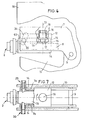
- FIG. 3 illustrates the invention in principle, according to which the axis 1 of the upper knife 2 is offset laterally next to the axis 3 of the lower knife 5 or next to the vertical plane 4.
- the amount n of displacement depends on the thickness of the board 6, from which, for. B. a round plate is to be cut out.
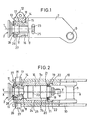
- the upper knife 2 is pivotally mounted to the side in the swivel arm 7.
- the swivel arm 7 carries or supports the drive shaft 8, which is connected to a universal joint with conventional drive means (not shown).
- the swivel arm 7 is pivotably seated with an axis 9 in the machine housing 10, which is only partially shown, in the area of the sheet metal passage.
- the swivel arm 7 leads the upper knife 2 to the board 6, whereupon the drive of the upper and possibly also lower knife is started and the cutting can begin.
- the swivel arm 7, which essentially consists of the two fork arms 7a and 7b, has a block 11 in the free end region.
- block 11 there is a bore 13 which merges with an annular step 14 into the bore 15 of smaller diameter.
- the bore 13 sits off-center in the block 11, as can be seen schematically in FIG. 4 and what is indicated by the different wall thicknesses in FIGS. 1 and 2.
- the center of block 11 is identified by plane X; the central axis of the bore 13 lies in the plane Z, that is offset by the amount E to the plane X.
- the pipe section 16 is positively supported, which has a peripheral edge 17 in the free end region, the edge of the edge 17 being supported against the ring step 14, which serves as a front abutment.
- the pipe section 16 carries an external thread 18, onto which a clamping ring 19 is screwed, against which a compression spring 20, which can be designed as a plate spring, is supported on the pipe section 16.
- Edges 21, which are introduced into recesses 22 in the fork arms 7a and 7b, are expediently used as counter bearings for the spring 20.
- Holes 23 can be provided in a row in the jacket of the tube piece 16, which serve to twist the tube, wherein an opening 24 or 25 can be provided in the housing 10 and in the fork arm 7b so that the holes 23 are accessible from the outside.
- the drive shaft 8 of the upper knife 2 is rotatably supported.
- a known support can be provided on ball or roller bearings (not shown).
- a spherical roller bearing or tapered roller bearing 26 is preferably used to support the drive shaft 8, the roller bearing being seated in a corresponding receiving bore 27 in the tube section 16 and on the shaft 8. It is important that the central axis of the pipe section 16 or the bore 27 is preferably also offset laterally to the Z plane by the amount E (FIG.
- the displacement amount of the bore 13 is preferably the same in size, but is provided spatially opposite, so that the two displacement amounts cancel each other out.
- the bore 27 is expediently covered at the front with a protective plate 28 on which a scale 29 or a pointer 30 can be arranged.
- the scale is arranged frontally on the swivel arm 7.
- Abutments 31 seated in the housing walls provide lateral support for the swivel arm 7 in a manner known per se.
- the swivel arm 7 thus supports the pipe section 16 offset eccentrically to the longitudinal plane X, the pipe section 16 on roller bearings supporting the knife shaft 8 eccentrically by the same amount E, but in the opposite direction, so that in the initial position of the device the vertical center plane Y or the axis Y of the upper knife coincides with the axis or vertical center plane X of the lower knife.
- the axis offset is accomplished by rotating the pipe section 16 with a handle inserted into the holes 23. Since the pipe section 16 supports the shaft 8 eccentrically, the axis Y of the upper knife 2 is offset to the axis X to the left or right, depending on the direction of rotation.
- the maximum achievable axis offset, which can be read on the scale 29, is equal to twice the eccentricity E.
- the upper knife 2 is pivotally mounted to the side in the swivel arm 7.
- the swivel arm 7 carries or supports the drive shaft 8, which is connected to a universal joint with conventional drive means (not shown).
- the Swivel arm 7 is pivotably seated with an axis 9 in the machine housing 10, which is only partially shown, in the area of the sheet metal passage 11.
- the swivel means for the swivel arm 7, which generally consists of a piston-cylinder unit, is not shown for reasons of clarity.
- the swivel arm 7 leads the upper knife 2 to the board 6, whereupon the drive of the upper and possibly also lower knife is started and the cutting can begin.
- a support plate 12 is inserted transversely between the two fork arms 7a and 7b in the swivel arm 7.
- a block 14 hangs laterally rotatable about a vertical or perpendicular axis 13 to the plate plane, which supports and guides the drive shaft 8 in a bushing 15, the upper knife 2 being seated on the end of the drive shaft 8 in a manner known per se.
- the pivot bearing for the block 14, which is square in cross section, has a threaded bolt 16.
- the bolt 16 is provided at the end with threaded sections 17 and 18, the threaded section 17 being screwed into the upper wall 19 of the block 14.
- a flange 20 adjoins section 17, which is seated in a corresponding recess 21 in upper wall 19.
- the central part 22 of the bolt 16 is rotatably inserted in a bush 23 which is divided in the middle and which is firmly embedded in a bore 24 in the support plate 12.
- the flange edge 20 is supported against the lower socket edge 25, while a stepped edge 28 of the nut 27, which is screwed onto the threaded portion 18, is supported against the upper socket edge 26.
- the block 14 and thus also the drive shaft 8 or the axis of the upper knife 2 is mounted laterally rotatable about the axis 13 in the swivel arm 7, thereby ensuring the lateral displacement of the upper knife axis relative to the lower knife axis.
- the pivoting of the upper knife 2 is accomplished with the abutments 29 and 30. These abutments each sit laterally in the fork arms 7a and 7b of the swivel arm 7 and act laterally on the block 14 in such a way that a lateral adjustment or pivoting can be set.
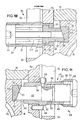
- the abutment 29 (FIG. 11) is expediently adjustable and the abutment 30 (FIG. 10) is designed to be fixed.
- the abutment 30 has a sleeve 31 which is screwed into the fork arm 7b with the thread 32. With the free part 33, the sleeve 31 engages through an obliquely arranged opening 34 in the machine housing 10.
- the support ring surface 39 is supported against a correspondingly bevelled abutment surface 40, which is larger in diameter than the surface 39 and is arranged in a bore 41 of the block 14 in the form of an insert 42.
- the support sleeve 37 is pressed in the sleeve 31 with a compression spring element 43 against the bottom edge 35, the spring element 43 being supported against a nut 44 screwed into the end of the sleeve 31.
- the nut 44 preferably has a stud 45 which passes through the spring element 43 and is guided in the bore 38 of the support sleeve 37.
- the pivoting is accomplished with the abutment 29. It also has a sleeve 46 which is screwed into the fork arm 7a of the swivel arm 7 with a thread 47.
- the free part 48 of the sleeve 46 also passes through an inclined opening 34 in the housing 10, so that the pivoting of the swivel arm 7 about the axis 9 is not hindered by the abutments 29 and 30.
- a stop bolt 49 slides in the sleeve 46 in a form-fitting manner, which passes through the sleeve mouth 50 and has an inclined surface 51 at the free end region.
- the inclined surface 51 sits on an inclined surface 52 of an insert 42, which consists of a material on which the inclined surface 51 can slide well and which is embedded in a bore 41 in the block 14.
- the bolt 49 has a collar 53, into which a longitudinal groove 54 is made, in which the shaft end of a screw 55 seated in the sleeve wall is inserted, so that the bolt 49 is secured against rotation.
- the collar 53 corresponds to a stop ring edge 56 in the sleeve 46 in that the bolt 49 can only be moved up to this stop edge.
- a threaded bolt 57 is screwed in, which abuts against the sliding bolt 49. If the threaded bolt 57 is screwed in, it moves the sliding bolt 49 against the block 14, which is pivoted to the side, against the spring pressure of the abutment 30. When the threaded bolt 57 is unscrewed, the block 14 pivots to the other side.
- a cap 58 can be arranged on the bolt 57, which facilitates the rotation of the bolt and can protect the thread 59 against contamination.
- a screw 60 can expediently be provided in a manner known per se which passes through a web 61 of the sleeve 46 and is screwed into the fork arm 7a.
- the pivoting path of the block 14 or the upper knife axis can be read off on a scale 62, which is either applied on the sleeve part 48 on the outside or frontally on the support plate 12 is marked.
- a pointer 63 is expediently arranged on the end wall of the block 14, which corresponds to the scale 62 on the support plate 12.
- a drive device for the circuit board is provided in the area of the circular knives of the circular shears, which automatically transports the circuit board, at least in the case of tangential and undersize cuts, at least until the circular knives have gripped the circuit board and in turn ensure transport.
- FIGS. 12 and 13 provides a rubber roller 102 as a driving roller, which sits on the drive shaft 105 of the upper knife 106.
- the circular shears in the exemplary embodiment shown have the machine housing 107, which is only partially and schematically drawn.
- the machine housing 107 forms the plate passage 108 and supports the drive shaft 105 and can be swiveled to the horizontal position (not shown).
- the shaft 113 of the lower knife 109 can be arranged in the machine housing 107 in a fixed and obliquely upward direction.
- the lower knife generally consists of the lower circular knife 110, the holding flange 111 and the nut 112 with which the circular knife 110 is screwed onto the shaft 113, which may be driven.
- the upper knife 106 has the circular knife 114, against which the holding flange 115 is placed, the nut 116 being screwed onto the drive shaft 105 and the circular knife 114 being positioned on the shaft 105.
- a driver roller 117 is preferably seated on the holding flange 115.
- the driver roller consists of the rear annular flange 101 and the front annular flange 103, between which a driver ring 102 made of an elastic material, e.g. B. rubber or plastic, clamped.
- the flange 101 has an annular groove 118 and the flange 103 has a corresponding annular groove 119, which are aligned in such a way that they form an annular chamber in which the driving ring 102 is clamped.
- the flange 103 is fastened to the flange 115 with screws, so that the ring 102 and the flange 101 are fixed on the circular knife 114.
- the outer diameter of the ring 102 is chosen according to the invention so large that it is ensured that the ring 102 takes the board 104 when the upper knife 106 is driven, even if z. B. the upper knife is not yet in engagement with the board 104, from which the circular blank 120 is to be cut out and which - as can be seen from FIGS. 1 and 2 - has undersize.
- the frictional force of the driving roller 117 should be selected so that even heavy, thick sheets can be moved without the roller 117 slipping.
- the outer diameter D of the driving roller 117 of the formula should suffice, where D is the diameter of the driving roller, d the diameter of the circular knife, S the sheet thickness (each given in mm) and K is a coefficient which varies between 1 and 3 depending on the type of material from which the driving ring 102 of the driving roller is made 117 is made.
- the operation of the drive device for the circuit board shown as an example is as follows: The upper knife is pivoted downwards in the working position. Since the sheet is under size, the driven knife is unable to set the board in motion. This is caused by the friction of the driving roller 117, which is brought into frictional contact with the sheet.
Landscapes
- Engineering & Computer Science (AREA)
- Mechanical Engineering (AREA)
- Details Of Cutting Devices (AREA)
- Perforating, Stamping-Out Or Severing By Means Other Than Cutting (AREA)
Claims (24)
Priority Applications (1)
| Application Number | Priority Date | Filing Date | Title |
|---|---|---|---|
| AT81101608T ATE8216T1 (de) | 1980-03-12 | 1981-03-06 | Kreisschere fuer die blechbearbeitung. |
Applications Claiming Priority (9)
| Application Number | Priority Date | Filing Date | Title |
|---|---|---|---|
| IT6422880U IT8064228V0 (it) | 1980-03-12 | 1980-03-12 | Rullo trascinatore per ottenere dischi da lamiere a misura o sottomisura. |
| IT6422880U | 1980-03-12 | ||
| IT6426780U | 1980-06-20 | ||
| IT6426780 | 1980-06-20 | ||
| IT6430180U | 1980-10-15 | ||
| ITVI1980U64301U IT8064301U1 (it) | 1980-10-15 | 1980-10-15 | Dispositivo eccentrico regolazione disassamento lame |
| DE3040348 | 1980-10-25 | ||
| DE3040346 | 1980-10-25 | ||
| DE3040333 | 1980-10-25 |
Publications (3)
| Publication Number | Publication Date |
|---|---|
| EP0035764A2 EP0035764A2 (fr) | 1981-09-16 |
| EP0035764A3 EP0035764A3 (en) | 1982-03-31 |
| EP0035764B1 true EP0035764B1 (fr) | 1984-07-04 |
Family
ID=27273750
Family Applications (1)
| Application Number | Title | Priority Date | Filing Date |
|---|---|---|---|
| EP81101608A Expired EP0035764B1 (fr) | 1980-03-12 | 1981-03-06 | Cisaille circulaire pour l'usinage de tôles |
Country Status (2)
| Country | Link |
|---|---|
| EP (1) | EP0035764B1 (fr) |
| DE (1) | DE3164509D1 (fr) |
Families Citing this family (2)
| Publication number | Priority date | Publication date | Assignee | Title |
|---|---|---|---|---|
| HU192140B (en) * | 1983-05-27 | 1987-05-28 | Nitrokemia Ipartelepek | Device for cutting plastic sheets advatageously glass fibre reinforced polyester ones |
| ITVI20090124A1 (it) * | 2009-05-29 | 2010-11-30 | T I M A C S R L | Apparecchiatura atta al taglio di dischi da fogli o bobina di limiera, in automatico, con una coppia di utensili indipendenti posti su assi rotanti motorizzati, facilmente regolabili ai vari diametri. |
Family Cites Families (8)
| Publication number | Priority date | Publication date | Assignee | Title |
|---|---|---|---|---|
| FR505135A (fr) * | 1919-01-29 | 1920-07-23 | Adolphe Kecheur | Perfectionnements aux cisailles circulaires |
| US2127002A (en) * | 1937-11-11 | 1938-08-16 | American Rolling Mill Co | Shearing device |
| US2209211A (en) * | 1939-05-31 | 1940-07-23 | Quickwork Company | Circle cutting attachment for rotary shears |
| US2256306A (en) * | 1940-07-31 | 1941-09-16 | Encor Corp | Circular shear for shearing circular metal plates |
| US2466947A (en) * | 1946-06-26 | 1949-04-12 | Horace R Harbord | Sheet shearing and flanging machine |
| US3117477A (en) * | 1958-02-12 | 1964-01-14 | Svetsmekano Ab | Plate cutting and bevelling machine |
| DE1652762A1 (de) * | 1968-03-14 | 1971-04-08 | Johann Kunz Soehne | Kurvenrollen-Bearbeitungsmaschine,insbesondere fuer Blech |
| DE2136268A1 (de) * | 1971-07-20 | 1973-02-01 | Matoni Maschinenbau Gmbh | Kreismesserschere |
-
1981
- 1981-03-06 DE DE8181101608T patent/DE3164509D1/de not_active Expired
- 1981-03-06 EP EP81101608A patent/EP0035764B1/fr not_active Expired
Also Published As
| Publication number | Publication date |
|---|---|
| EP0035764A3 (en) | 1982-03-31 |
| EP0035764A2 (fr) | 1981-09-16 |
| DE3164509D1 (en) | 1984-08-09 |
Similar Documents
| Publication | Publication Date | Title |
|---|---|---|
| EP0242733B1 (fr) | Dispositif pour scier | |
| DE3106353C2 (fr) | ||
| EP0252418A1 (fr) | Guillotine | |
| EP0491120B1 (fr) | Scie à ruban pour métaux | |
| DE3416664C2 (de) | Einrichtung zum Steuern der Schneidgeschwindigkeit des Sägeblattes einer Bandsägemaschine | |
| EP0012404A1 (fr) | Scie circulaire à couteau diviseur | |
| EP0575586B1 (fr) | Protection anti-eclatement pour scies mecaniques a lame de scie | |
| DE10152910A1 (de) | Schälgerät mit schwenkbarem Schälkopf | |
| DE3927275A1 (de) | Bandsaegemaschine | |
| EP0035764B1 (fr) | Cisaille circulaire pour l'usinage de tôles | |
| EP0654333A1 (fr) | Machine à travailler des pièces à usiner en bois, plastique ou similaires | |
| EP0034830A2 (fr) | Cisaille pour matières en barres, en particulier pour produits laminés | |
| DE2129813A1 (de) | Horizontal-Bandsaegemaschine | |
| DE3347920C2 (de) | Sägeeinrichtung | |
| DE3615381C2 (de) | Fuehrungsvorrichtung fuer den messerbalken einer schere zur blechbearbeitung | |
| DE2244421A1 (de) | Druckmittelbetaetigter messerhalter fuer laengsschnittstationen an papierschneidemaschinen | |
| DE1956879A1 (de) | Kopiervorrichtung fuer Werkzeugmaschinen | |
| EP0076526B1 (fr) | Dispositif de coupage | |
| DE19817656B4 (de) | Handwerkzeugmaschine, insbesondere Stichsäge | |
| DE69403591T2 (de) | Kombinierte Tisch- und Gehrungssäge | |
| DE3244402A1 (de) | Schneidvorrichtung fuer bogen und hefte | |
| DE48788C (de) | Kegelräderantrieb für die Scheibenmesser von Kreisscheeren | |
| DE2925401C2 (de) | Stichsäge mit Motorantrieb | |
| DE19602537C2 (de) | Vorschubeinrichtung zum Transport von sich in Längsrichtung erstreckenden Werkstücken, zum Beispiel einem Balken oder einem Träger | |
| DE3040348A1 (de) | Kreisschere fuer die blechbearbeitung |
Legal Events
| Date | Code | Title | Description |
|---|---|---|---|
| PUAI | Public reference made under article 153(3) epc to a published international application that has entered the european phase |
Free format text: ORIGINAL CODE: 0009012 |
|
| AK | Designated contracting states |
Designated state(s): AT BE CH DE FR GB IT LU NL SE |
|
| PUAL | Search report despatched |
Free format text: ORIGINAL CODE: 0009013 |
|
| AK | Designated contracting states |
Designated state(s): AT BE CH DE FR GB IT LU NL SE |
|
| 17P | Request for examination filed |
Effective date: 19820306 |
|
| ITF | It: translation for a ep patent filed | ||
| GRAA | (expected) grant |
Free format text: ORIGINAL CODE: 0009210 |
|
| AK | Designated contracting states |
Designated state(s): AT BE CH DE FR GB IT LI LU NL SE |
|
| REF | Corresponds to: |
Ref document number: 8216 Country of ref document: AT Date of ref document: 19840715 Kind code of ref document: T |
|
| REF | Corresponds to: |
Ref document number: 3164509 Country of ref document: DE Date of ref document: 19840809 |
|
| ET | Fr: translation filed | ||
| PG25 | Lapsed in a contracting state [announced via postgrant information from national office to epo] |
Ref country code: AT Effective date: 19850306 |
|
| PG25 | Lapsed in a contracting state [announced via postgrant information from national office to epo] |
Ref country code: SE Effective date: 19850307 |
|
| PG25 | Lapsed in a contracting state [announced via postgrant information from national office to epo] |
Ref country code: LU Free format text: LAPSE BECAUSE OF NON-PAYMENT OF DUE FEES Effective date: 19850331 Ref country code: BE Effective date: 19850331 |
|
| PLBE | No opposition filed within time limit |
Free format text: ORIGINAL CODE: 0009261 |
|
| STAA | Information on the status of an ep patent application or granted ep patent |
Free format text: STATUS: NO OPPOSITION FILED WITHIN TIME LIMIT |
|
| 26N | No opposition filed | ||
| BERE | Be: lapsed |
Owner name: TIMAC S.R.L. Effective date: 19850306 |
|
| PG25 | Lapsed in a contracting state [announced via postgrant information from national office to epo] |
Ref country code: NL Effective date: 19851001 |
|
| GBPC | Gb: european patent ceased through non-payment of renewal fee | ||
| NLV4 | Nl: lapsed or anulled due to non-payment of the annual fee | ||
| PG25 | Lapsed in a contracting state [announced via postgrant information from national office to epo] |
Ref country code: LI Effective date: 19860331 Ref country code: CH Effective date: 19860331 |
|
| PG25 | Lapsed in a contracting state [announced via postgrant information from national office to epo] |
Ref country code: FR Free format text: LAPSE BECAUSE OF NON-PAYMENT OF DUE FEES Effective date: 19861128 |
|
| REG | Reference to a national code |
Ref country code: CH Ref legal event code: PL |
|
| REG | Reference to a national code |
Ref country code: FR Ref legal event code: ST |
|
| PG25 | Lapsed in a contracting state [announced via postgrant information from national office to epo] |
Ref country code: GB Effective date: 19881118 |
|
| PG25 | Lapsed in a contracting state [announced via postgrant information from national office to epo] |
Ref country code: DE Effective date: 19881201 |
|
| EUG | Se: european patent has lapsed |
Ref document number: 81101608.8 Effective date: 19860128 |