EP0035828A2 - Kathodenstrahl-Fluoreszenzlampe und dazugehörige Schaltungselemente - Google Patents
Kathodenstrahl-Fluoreszenzlampe und dazugehörige Schaltungselemente Download PDFInfo
- Publication number
- EP0035828A2 EP0035828A2 EP81300387A EP81300387A EP0035828A2 EP 0035828 A2 EP0035828 A2 EP 0035828A2 EP 81300387 A EP81300387 A EP 81300387A EP 81300387 A EP81300387 A EP 81300387A EP 0035828 A2 EP0035828 A2 EP 0035828A2
- Authority
- EP
- European Patent Office
- Prior art keywords
- grid
- cathode
- lamp
- cylinder
- anode
- Prior art date
- Legal status (The legal status is an assumption and is not a legal conclusion. Google has not performed a legal analysis and makes no representation as to the accuracy of the status listed.)
- Withdrawn
Links
Images



Classifications
-
- H—ELECTRICITY
- H01—ELECTRIC ELEMENTS
- H01J—ELECTRIC DISCHARGE TUBES OR DISCHARGE LAMPS
- H01J63/00—Cathode-ray or electron-stream lamps
- H01J63/02—Details, e.g. electrode, gas filling, shape of vessel
Definitions
- This invention relates to cathodoluminescent light sources and to electric lighting arrangements including such sources.
- a cathodoluminescent light source consists of an electric lamp which includes an evacuated bulbous glass envelope with an integral glass neck terminated by a cap, an anode constituted by an electrically conductive coating on at least part of the interior surface of the bulb wall, such that at least part of the bulb wall is light transmissive, a layer of phosphor on the whole of the interior of the bulb wall and overlying the said anode coating, which phosphor is excitable to luminescence by electron bombardment, a dome-shaped grid located within the bulb adjacent to the junction between the bulb and neck of the envelope, and supported by a hollow metal cylinder disposed coaxially within the envelope neck, an electron emissive cathode mounted within the assembly of the grid and its supporting cylinder, which cathode is so shaped, and/or so located within the said grid assembly, that the electrons emitted from the cathode in operation of the lamp are substantially uniformly distributed over the whole of the surface of the grid on which they impinge, and
- the anode preferably covers the whole of the interior surface of the bulb wall and may consist of a known type of light transmissive electrically conducting coating formed, for example, of tin oxide and/or indium oxide.
- part of the bulb may be provided with an internally reflective metal coating which also serves as at least part of the anode, the remainder of the bulb either being free from any conductive coating or, preferably, having a light transmissive conducting coating to provide continuity of the anode over the whole of the bulb wall.
- the grid is preferably formed of metal mesh, for example of nickel or stainless steel.
- the cylindrical grid support member may be formed of any gas-free metal conventionally used for a similar purpose in, for example, thermionic valves or cathode ray tubes, such as a nickel-iron alloy; however, the cylinder is advantageously formed of a metal. having gettering properties, such as titanium, tantalum, or zirconium.
- a second metal cylinder may be mounted concentrically around the grid-supporting cylinder, and this second cylinder may also support a second grid, for example in the form of a second metal mesh dome, or a plate with a single aperture, such plate being located within the mesh grid.
- a double cylinder or double grid arrangement may be required, in some cases, for modifying the electron distribution and the electrical characteristics of the lamp.
- the cathode is of effectively circular form and is located coaxially within the grid assembly so that the electron-emissive part thereof lies in the region of the junction between the grid and its supporting cylinder.
- the term "effectively circular” is to be understood to mean that the cathode is so shaped and arranged that, in plan view as observed from the centre of the bulb interior, it has the appearance of a circle or a nearly closed circle.
- the cathode may be of the directly heated type, preferably of filamentary form, consisting of a single coil or coiled coil, of refractory metal wire, incorporating electron emissive material; the filament is of "wreath" form, that is to say the coil is effectively circular, as defined above, forming a nearly closed circle: this effect can be achieved by a circular or zig-zag form of mounting, the zig-zag arrangement enabling a greater length of coil to be used.
- the cathode may be of the indirectly heated type, suitably consisting of a hollow metal cylinder capped with a metal disc which is coated externally with electron emissive material, with a heating coil located within and insulated from the cylinder.
- an effectively circular cathode located adjacent to the grid, as described above, ensures that the electrons emitted from the cathode in operation of the lamp are substantially uniformly distributed over the surface of the grid.
- a filamentary cathode in the form of a linear coil of wire, in particular because linear coil filaments are more readily mass produced by automatic means than "wreath" filaments.
- the cathode in a second form of lamp in accordance with the invention, therefore, consists of a linear wire coil filament incorporating electron emissive material, the coil being disposed orthogonally to the longitudinal axis of the assembly of the grid and its supporting cylinder, and the cathode is located within the grid supporting cylinder in a position nearer to the open end of the cylinder remote from the grid than to the end thereof on which the grid is supported.
- the cathode may be a single coil or coiled coil of refractory metal wire, and is supported on two or more wires so that it lies straight.
- a metal disc of substantially the same diameter as the cylinder located close to, and either inside or outside, but out of contact with, the said open end'of.the cylinder and disposed coaxially with the cylinder, and connected to that lead to the cathode to which a negative potential will be applied in operation, the disc having a central aperture permitting the passage of the cathode leads therethrough.
- the wires supporting a filamentary cathode may be sealed into or through a glass bead in conventional manner.
- the cathode assembly so formed, or a cylindrical indirectly heated cathode, and the grid cylinder or cylinders may be supported on wires sealed into the closure of the neck of the lamp envelope, which closure is suitably a pinched foot tube of the form conventionally used in the manufacture of incandescent lamps, and current conducting leads from contacts on the lamp cap to the cathode and grid may be constituted by, or may incorporate, such support wires.
- a metal disc incorporated in the aforesaid second form of lamp, for repelling electrons emerging from the open end of the grid supporting cylinder, may also be supported by a wire sealed into the neck closure.
- the lead to the anode is located along the exterior of the envelope neck, being connected to the anode by an end of the lead wire sealed through the envelope wall, and said lead extending to a contact provided on the exterior of the neck.
- glasses of the type generally used for incandescent lamp envelopes such as conventional soda-lime glasses, may be unsuitable for use for the envelope of a lamp in accordance with the invention, in particular because such glasses permit the transmission of X-rays generated by the electron bombardment of the envelope.
- the envelope is therefore preferably formed of an X-ray inhibiting glass, for example a lead glass.
- the invention further provides an electric lighting arrangement consisting of a lamp of either of the forms described above, and a circuit arrangement for operating said lamp from-a source of electric current supply, which circuit arrangement includes means for converting the supply voltage to unidirectional operating potentials of required magnitudes for application respectively to the anode, cathode and grid of the'lamp.
- the circuit arrangement for operation from a standard mains supply, therefore includes step-up means, suitably comprising a high frequency oscillator, a transformer, and a voltage multiplying system.
- the circuit will also include current limiting means for applying a low voltage, usually between 6 and 40 volts, which is negative with respect to the grid potential across the cathode, and usually also means for reducing the supply voltage for the application of a suitable potential to the grid.
- the grid potential may be from 40 to 250 volts, the magnitude of the grid potential required depending upon the configuration of the cathode-grid assembly: thus the greater the spacing apart of the cathode and grid, the greater is the grid potential required. If, as is usual, the lamp is to be operated from an alternating current supply, rectification will of course be required, and where an oscillator is employed as part of the step-up arrangement for providing the anode potential, further rectifying means will be required to be inserted between the transformer and the connection to the anode.
- the circuit arrangement may be contained within a housing which is detachably mounted on the lamp cap and which is insertable into a lamp-holder, the circuit-housing assembly incorporating contacts arranged to co-operate with the contacts on the lamp cap and/or neck, and the housing also carrying external contacts for connecting the circuit arrangement to the supply by co-operation with contacts in a lampholder.
- the circuit arrangement may be incorporated in or associated with a lampholder which includes a socket having contacts arranged to co-operate with the contacts on the lamp for connection of the circuit thereto.
- a lamp in accordance with the invention has the additional advantage that it can be of a robust and relatively simple construction which is not critical dimensionally.
- the lamp shown in Figure 1 comprises an evacuated envelope 1 formed of lead glass, consisting of a bulb 2 of substantially paraboloid shape, with a slightly curved front face 3, and an integral neck 4 in which an electron gun assembly is mounted, and which is closed in conventional manner by a pinched glass foot tube 5.
- the paraboloid rear portion 2 of the bulb wall is internally coated with aluminium, 6, and the front face 3 is internally coated with a transparent film ? of conducting material, suitably tin oxide and/or indium oxide: these coatings together constitute the anode, the aluminium coating also serving as a reflector, and are overlaid by a layer of phosphor 8, which may be of any known electron-responsive type.
- the thicknesses of the coatings are exaggerated in the drawing.
- the electron gun assembly includes a cathode and a grid.
- the cathode is in the form of a wreath type filament 9, composed of a single coil of tungsten wire activated with one or more of the oxides of barium, strontium and calcium, mounted in zig-zag manner on five support wires sealed into a glass bead 10, the wires 11 to which the ends of the coil are attached being extended through the glass bead and joined to nickel wires 12 which are sealed through the foot tube 5 and which constitute supports for, and conducting leads to, the cathode.
- the grid consists of a dome-shaped structure 13 of nickel wire mesh, supported on a titanium cylinder 14 which is carried by a nickel bracket 15 attached to a nickel lead wire 16 sealed through the foot tube. Barium/ aluminium getter rings 1? are supported by wires 18 attached to the lead wires to the cathode and grid.
- the closed end of the bulb neck is cemented into a brass cap 19, in known manner.
- the cap carries contacts 20, insulated from the brass, to which the cathode leads 12 are connected, and the grid lead 16 is connected to the cap itself, which thus constitutes the grid contact.
- the cap is provided with locating pins 21, preferably three in number to ensure correct orientation of the lamp in a lampholder for connection of the lamp contacts to the operating circuit.
- connection to the anode 6, 7 is made by means of a wire 22 of metal having a suitable thermal expansion match to the envelope glass, which wire is sealed through the envelope at the junction of the neck and the aluminised portion of the bulb, and a coating of carbon 23 is applied to the interior of the neck-bulb junction region, covering the internal end of the wire 22 and part of the aluminium coating, to ensure reliability of the anode connection.
- the wire 22 extends along the exterior of the neck as shown at 24, and is covered by a strip coating of carbon 25 which constitutes the anode contact.
- the envelope of the general service lamp shown in Figure 2 consists of an evacuated bulb 26 of oblate spheroid shape with an integral neck 27, formed of lead glass, the neck being closed by a pinched glass foot tube 5 and surmounted by a brass cap 19.
- the whole of the internal surface of the bulb has a transparent film coating 28 of conducting material forming the anode, covered with a layer of electron-responsive phosphor 29. If desired, the phosphor may be coated with an aluminium film, in known manner, to enhance the light output of the lamp.
- the arrangement of cathode, grid, and conducting leads and contacts for the anode, cathode and grid is similar to that employed in the reflector lamp described above with reference to Figure 1, and getters and locating pins as described with reference to Figure 1 are also provided.
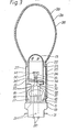
- the lamp shown in Figure 3 is similar to that shown in Figure 2 in respect of its outward form, consisting of an evacuated oblate spheroid lead glass bulb 26 and integral neck 27, with a pinched glass foot tube closure 5 and a brass cap 19, the whole of the internal surface of the bulb having an anode coating consisting of a film 28 of transparent conducting material, overlaid by a layer of electron-responsive phosphor 29.
- the electron gun assembly mounted within the neck 27, includes a dome-shaped grid 13 of nickel wire mesh, supported on a titanium cylinder 14, a cathode 30 in the form of a straight single coil of tungsten wire incorporating electron emissive material, which is located in the lower part of the cylinder 14, and a titanium disc 31 which has a central aperture 32 and which is located immediately below the open lower end of the cylinder 14.
- the cathode coil 30 is mounted on four support wires 33 sealed into a glass bead 34, the wires to which the ends of the coil are attached being extended through the aperture 32 in the disc 31 and joined to nickel wires 35 which are sealed through the foot tube 5 and which constitute supports for, and conducting leads to, the cathode, being connected.to contacts 20 carried by and insulated from the lamp cap 19.
- the disc 31 is supported by a nickel bracket 36 and nickel wire 371 the latter also being sealed into the foot tube; the wire 37 is connected to the negative lead to the cathode, as shown at 3 8 .
- An electron gun assembly of the form described with reference to Figure 3 may also be incorporated in a reflector lamp which in other respects is of the form shown in Figure 1.
- a lamp of any of the forms shown in Figures 1, 2 and 3 is inserted into a lampholder, or a housing insertable into a lampholder, in which a circuit arrangement for operating the lamp from an electric current supply is mounted, and which includes a socket formed of insulating material extending along substantially the whole length of the lamp neck, so as to cover the anode lead wire 22 and the carbon strip 25 on the exterior of the neck.
- the socket carries internal contacts arranged to co-operate with the said carbon strip, the contacts 20 and the cap 19, for connection of the anode, cathode and grid respectively to the operating circuit.
- FIG 4 shows, by way of example only, one form of circuit arrangement which can be employed for operating a lamp of any of the forms described above with reference to Figures 1, 2 and 3, from a 240 volts alternating current supply.
- This circuit arrangement is made up of conventional components, and includes essentially a full wave rectifier 39, connected across the supply terminals 40 and 41, a step-up transformer 42 and voltage multiplying arrangement 43 for applying the requisite potential in the range of 5 to 15 kilovolts to the lamp anode 44, and subsidiary circuits for applying suitable potentials to the lamp cathode and grid.
- a current limiting arrangement for reducing the current from the rectifier 39 to the lamp cathode 45, this arrangement including a smoothing condenser 46 and a zener diode 47 for maintaining the cathode potential constant, and negative with respect to the grid potential, suitably at 10 volts.
- the connection to the lamp grid 48 is in a line in parallel with the cathode circuit; the grid potential is reduced, suitably to 100 volts in the case of a lamp of either of the forms shown in Figures 1 and 2 or to 150 volts in the case of a lamp of the form shown in Figure 3, by resistors 49 and 50, and is smoothed by condenser 51.
- the arrangement for supplying the anode potential includes, in addition to the transformer and the voltage multiplier, an integrated oscillator circuit 52, with means including diode 53 and condenser 54 for applying a suitable d.c. voltage thereto; the oscillations produced, at a suitable frequency of about 10 kilohertz, are transmitted to the transformer 42 via the transistor 55.
- a slow start arrangement, including condenser 56 and resistor 57, is associated with the oscillator for preventing the application of the high potential to the anode before the cathode has attained its operating temperature. Feed-back to the oscillator from the voltage multiplier is provided via resistor 58. The use of the oscillator in this manner enables a transformer of small size to be employed for obtaining the desired step-up ratio.
- This circuit arrangement provides a safety factor in the operation of the lamp, in that the cathode is so connected that if the cathode circuit is broken there is no current supply to the oscillator, arid hence no high potential can be applied to the anode.
Landscapes
- Vessels And Coating Films For Discharge Lamps (AREA)
- Discharge Lamp (AREA)
Applications Claiming Priority (4)
| Application Number | Priority Date | Filing Date | Title |
|---|---|---|---|
| GB8006549 | 1980-02-27 | ||
| GB8006549 | 1980-02-27 | ||
| GB8018285 | 1980-06-04 | ||
| GB8018285 | 1980-06-04 |
Publications (2)
| Publication Number | Publication Date |
|---|---|
| EP0035828A2 true EP0035828A2 (de) | 1981-09-16 |
| EP0035828A3 EP0035828A3 (de) | 1982-01-27 |
Family
ID=26274621
Family Applications (1)
| Application Number | Title | Priority Date | Filing Date |
|---|---|---|---|
| EP81300387A Withdrawn EP0035828A3 (de) | 1980-02-27 | 1981-01-30 | Kathodenstrahl-Fluoreszenzlampe und dazugehörige Schaltungselemente |
Country Status (4)
| Country | Link |
|---|---|
| US (1) | US4352043A (de) |
| EP (1) | EP0035828A3 (de) |
| AU (1) | AU535321B2 (de) |
| GB (1) | GB2070849B (de) |
Cited By (8)
| Publication number | Priority date | Publication date | Assignee | Title |
|---|---|---|---|---|
| EP0054356A1 (de) * | 1980-12-17 | 1982-06-23 | THE GENERAL ELECTRIC COMPANY, p.l.c. | Kathodolumineszente Lichtquellen und aus solchen Lichtquellen bestehende Beleuchtungseinrichtungen |
| EP0102139A3 (de) * | 1982-08-19 | 1984-11-07 | Osram- Gec Limited | Kathodolumineszierende Lichtquellen und Lichtanlagen mit solcher Quellen |
| EP0205011A3 (en) * | 1985-06-10 | 1989-05-10 | International Business Machines Corporation | High intensity light source |
| WO2008098013A3 (en) * | 2007-02-05 | 2008-10-02 | Telegen Corp | System and apparatus for cathodoluminescent lighting |
| US8035293B2 (en) | 2004-12-16 | 2011-10-11 | Vu1 Corporation | Cold-cathode light-emitting device with defocusing grid and associated methods of manufacturing |
| US8294367B2 (en) | 2007-02-05 | 2012-10-23 | Vu1 Corporation | System and apparatus for cathodoluminescent lighting |
| WO2013098239A1 (en) * | 2011-12-28 | 2013-07-04 | Lightlab Sweden Ab | Power supply for a field emission light source |
| EP2784800A1 (de) * | 2013-03-25 | 2014-10-01 | LightLab Sweden AB | Geformte Kathode für Feldemissionsanordnung |
Families Citing this family (14)
| Publication number | Priority date | Publication date | Assignee | Title |
|---|---|---|---|---|
| US4585976A (en) * | 1982-01-19 | 1986-04-29 | Hewlett-Packard Company | Beam penetration CRT with internal automatic constant deflection factor and pattern correction |
| US4737683A (en) * | 1985-04-10 | 1988-04-12 | Hangzhon University | High luminance color picture element tubes |
| DE69027930T2 (de) * | 1990-05-10 | 1997-02-27 | Imaging & Sensing Tech | Aus einer Kathodenstrahlröhre bestehende Lampe für Leuchtanzeigen und Verfahren zum Erzielen einer gleichmässig beleuchteten Fläche |
| HU217752B (hu) * | 1994-04-18 | 2000-04-28 | General Electric Co. | Elektród nélküli, fluoreszkáló reflektorlámpa |
| SE510412C2 (sv) * | 1997-06-13 | 1999-05-25 | Lightlab Ab | En ljuskälla innefattande en fältemissionskatod och en fältemissionskatod för användning i en ljuskälla |
| SE510413C2 (sv) * | 1997-06-13 | 1999-05-25 | Lightlab Ab | En fältemissionskatod och en ljuskälla innefattande en fältemissionskatod |
| GB2346007B (en) | 1999-01-21 | 2004-03-03 | Imaging & Sensing Tech Corp | Getter flash shield |
| EP3333280B1 (de) * | 2007-09-12 | 2026-04-01 | Flisom AG | Verfahren zur herstellung einer verbindungsschicht mit zusammensetzungsgradierung |
| US7978804B2 (en) * | 2007-12-10 | 2011-07-12 | Schlumberger Technology Corporation | Low power neutron generators |
| RU2382436C1 (ru) * | 2008-10-21 | 2010-02-20 | Государственное учебно-научное учреждение Физический факультет Московского государственного университета имени М.В. Ломоносова | Диодная катодолюминесцентная лампа |
| CA2758689A1 (en) * | 2009-03-30 | 2010-10-14 | Vu1 Corporation | System and method of manufacturing a cathodoluminescent lighting device |
| US8183760B2 (en) * | 2010-06-15 | 2012-05-22 | Osram Sylvania Inc. | Coils for electron discharge devices |
| US20140153254A1 (en) * | 2012-12-04 | 2014-06-05 | General Electric Company | Lamp with integrated electronics and thermally protective features |
| US9739471B1 (en) * | 2016-04-12 | 2017-08-22 | Tse Min Chen | LED lamp bulb |
Family Cites Families (7)
| Publication number | Priority date | Publication date | Assignee | Title |
|---|---|---|---|---|
| GB749448A (en) * | 1952-04-22 | 1956-05-23 | Sebel S A | Electronic fluorescent illuminating lamp |
| US2907909A (en) * | 1957-07-05 | 1959-10-06 | Du Mont Allen B Lab Inc | Light source |
| US3299305A (en) * | 1963-06-28 | 1967-01-17 | Burroughs Corp | Cathode ray circuit condition indicator tube |
| US3377492A (en) * | 1965-08-03 | 1968-04-09 | Hughes Aircraft Co | Flood gun for storage tubes having a dome-shaped cathode and dome-shaped grid electrodes |
| US3746909A (en) * | 1970-10-26 | 1973-07-17 | Northrop Corp | Area electron flood gun |
| US3917968A (en) * | 1974-02-22 | 1975-11-04 | Texas Instruments Inc | Area flood gun |
| FR2389226A1 (fr) * | 1977-04-30 | 1978-11-24 | English Electric Valve Co Ltd | Indicateur optique |
-
1981
- 1981-01-30 EP EP81300387A patent/EP0035828A3/de not_active Withdrawn
- 1981-01-30 GB GB8102935A patent/GB2070849B/en not_active Expired
- 1981-02-06 US US06/232,169 patent/US4352043A/en not_active Expired - Lifetime
- 1981-02-10 AU AU67129/81A patent/AU535321B2/en not_active Ceased
Cited By (15)
| Publication number | Priority date | Publication date | Assignee | Title |
|---|---|---|---|---|
| EP0054356A1 (de) * | 1980-12-17 | 1982-06-23 | THE GENERAL ELECTRIC COMPANY, p.l.c. | Kathodolumineszente Lichtquellen und aus solchen Lichtquellen bestehende Beleuchtungseinrichtungen |
| EP0102139A3 (de) * | 1982-08-19 | 1984-11-07 | Osram- Gec Limited | Kathodolumineszierende Lichtquellen und Lichtanlagen mit solcher Quellen |
| EP0205011A3 (en) * | 1985-06-10 | 1989-05-10 | International Business Machines Corporation | High intensity light source |
| US8035293B2 (en) | 2004-12-16 | 2011-10-11 | Vu1 Corporation | Cold-cathode light-emitting device with defocusing grid and associated methods of manufacturing |
| US8058789B2 (en) | 2007-02-05 | 2011-11-15 | Vu1 Corporation | Cathodoluminescent phosphor lamp having extraction and diffusing grids and base for attachment to standard lighting fixtures |
| US7834553B2 (en) | 2007-02-05 | 2010-11-16 | Vu1 Corporation | System and apparatus for cathodoluminescent lighting |
| WO2008098013A3 (en) * | 2007-02-05 | 2008-10-02 | Telegen Corp | System and apparatus for cathodoluminescent lighting |
| US8102122B2 (en) | 2007-02-05 | 2012-01-24 | Vu1 Corporation | System and apparatus for cathodoluminescent lighting |
| US8294367B2 (en) | 2007-02-05 | 2012-10-23 | Vu1 Corporation | System and apparatus for cathodoluminescent lighting |
| WO2013098239A1 (en) * | 2011-12-28 | 2013-07-04 | Lightlab Sweden Ab | Power supply for a field emission light source |
| CN104025718A (zh) * | 2011-12-28 | 2014-09-03 | 瑞典莱特兰博公司 | 场发射光源用电源 |
| US9237622B2 (en) | 2011-12-28 | 2016-01-12 | Lightlab Sweden Ab | Power supply for a field emission light source |
| CN104025718B (zh) * | 2011-12-28 | 2016-04-13 | 瑞典莱特兰博公司 | 场发射光源用电源 |
| EP2784800A1 (de) * | 2013-03-25 | 2014-10-01 | LightLab Sweden AB | Geformte Kathode für Feldemissionsanordnung |
| WO2014154505A1 (en) * | 2013-03-25 | 2014-10-02 | Lightlab Sweden Ab | Shaped cathode for a field emission arrangement |
Also Published As
| Publication number | Publication date |
|---|---|
| GB2070849A (en) | 1981-09-09 |
| US4352043A (en) | 1982-09-28 |
| AU6712981A (en) | 1981-09-03 |
| AU535321B2 (en) | 1984-03-15 |
| EP0035828A3 (de) | 1982-01-27 |
| GB2070849B (en) | 1983-11-09 |
Similar Documents
| Publication | Publication Date | Title |
|---|---|---|
| US4352043A (en) | Cathodoluminescent light sources and electric lighting arrangements including such sources | |
| US8058789B2 (en) | Cathodoluminescent phosphor lamp having extraction and diffusing grids and base for attachment to standard lighting fixtures | |
| US5841229A (en) | Amalgam support arrangement for an electrodeless discharge lamp | |
| EP1498931B1 (de) | Kathodolumineszente lichtquelle | |
| US4506194A (en) | Cathodoluminescent light sources and electric lighting arrangements including such sources | |
| US5210461A (en) | Arc discharge lamp containing mechanism for extinguishing arc at end-of-life | |
| US2103041A (en) | Gaseous electric discharge lamp device | |
| US4272703A (en) | D.C. Voltage fluorescent lamp | |
| GB2097181A (en) | Cathodoluminescent lamps | |
| JP2002042735A (ja) | 蛍光ランプ | |
| EP0054356A1 (de) | Kathodolumineszente Lichtquellen und aus solchen Lichtquellen bestehende Beleuchtungseinrichtungen | |
| US4413204A (en) | Non-uniform resistance cathode beam mode fluorescent lamp | |
| US2438181A (en) | Fluorescent and/or cathode glow lamp and method | |
| US2252474A (en) | Discharge device | |
| US2103078A (en) | Gaseous electric discharge lamp | |
| US2692347A (en) | Metalized stems for low-pressure discharge tubes | |
| US2832912A (en) | Electric discharge device | |
| US2838705A (en) | Color-corrected reflector high pressure mercury vapor lamp and method of preparing | |
| US3069581A (en) | Low pressure discharge lamp | |
| US2009211A (en) | Gaseous electric discharge device | |
| US5276379A (en) | Arc discharge lamp having cementless base members | |
| US5239229A (en) | Glow discharge lamp with auxiliary electrode for mounting getter thereon | |
| US2054048A (en) | Signal lamp | |
| US5049785A (en) | Two contact, AC-operated negative glow fluorescent lamp | |
| US2025585A (en) | Method of operating vapor electric lamps |
Legal Events
| Date | Code | Title | Description |
|---|---|---|---|
| PUAI | Public reference made under article 153(3) epc to a published international application that has entered the european phase |
Free format text: ORIGINAL CODE: 0009012 |
|
| AK | Designated contracting states |
Designated state(s): BE DE FR IT NL |
|
| PUAL | Search report despatched |
Free format text: ORIGINAL CODE: 0009013 |
|
| AK | Designated contracting states |
Designated state(s): BE DE FR IT NL |
|
| RAP1 | Party data changed (applicant data changed or rights of an application transferred) |
Owner name: THE GENERAL ELECTRIC COMPANY, P.L.C. |
|
| 17P | Request for examination filed |
Effective date: 19820712 |
|
| STAA | Information on the status of an ep patent application or granted ep patent |
Free format text: STATUS: THE APPLICATION HAS BEEN WITHDRAWN |
|
| 18W | Application withdrawn |
Withdrawal date: 19840117 |
|
| RIN1 | Information on inventor provided before grant (corrected) |
Inventor name: RIGDEN, SYDNEY ALFRED RICHARD |