EP0035832A2 - Bras de chargement - Google Patents
Bras de chargement Download PDFInfo
- Publication number
- EP0035832A2 EP0035832A2 EP81300539A EP81300539A EP0035832A2 EP 0035832 A2 EP0035832 A2 EP 0035832A2 EP 81300539 A EP81300539 A EP 81300539A EP 81300539 A EP81300539 A EP 81300539A EP 0035832 A2 EP0035832 A2 EP 0035832A2
- Authority
- EP
- European Patent Office
- Prior art keywords
- pair
- elbows
- loading arm
- swivel
- axis
- Prior art date
- Legal status (The legal status is an assumption and is not a legal conclusion. Google has not performed a legal analysis and makes no representation as to the accuracy of the status listed.)
- Granted
Links
Images

Classifications
-
- B—PERFORMING OPERATIONS; TRANSPORTING
- B67—OPENING, CLOSING OR CLEANING BOTTLES, JARS OR SIMILAR CONTAINERS; LIQUID HANDLING
- B67D—DISPENSING, DELIVERING OR TRANSFERRING LIQUIDS, NOT OTHERWISE PROVIDED FOR
- B67D9/00—Apparatus or devices for transferring liquids when loading or unloading ships
- B67D9/02—Apparatus or devices for transferring liquids when loading or unloading ships using articulated pipes
-
- Y—GENERAL TAGGING OF NEW TECHNOLOGICAL DEVELOPMENTS; GENERAL TAGGING OF CROSS-SECTIONAL TECHNOLOGIES SPANNING OVER SEVERAL SECTIONS OF THE IPC; TECHNICAL SUBJECTS COVERED BY FORMER USPC CROSS-REFERENCE ART COLLECTIONS [XRACs] AND DIGESTS
- Y10—TECHNICAL SUBJECTS COVERED BY FORMER USPC
- Y10T—TECHNICAL SUBJECTS COVERED BY FORMER US CLASSIFICATION
- Y10T137/00—Fluid handling
- Y10T137/8593—Systems
- Y10T137/8807—Articulated or swinging flow conduit
Definitions
- This invention relates to loading arms and particularly loading arms providing for removal of vapor from a tank being filled.
- vapors which preferably are removed from the tank as it is filled.
- vapors may be present in a tank before it is filled which are desirably removed during the filling operation.
- a swivel joint system is connected to the outboard end of the outboard arm and provides for movement of the flange connector of the loading arm in three mutually perpendicular planes. This is particularly true with loading arms which are connected to ships where movement of the ship during loading is a common occurrence.
- Such triple swivel joint assemblies for handling liquids in a single arm are standard in the industry.
- Some ships have loading manifolds in which the liquid and vapor connector flanges are arranged generally side-by-side.
- This invention provides a loading arm which may be connected,to side-by-side liquid and vapor flanges while providing for the liquid and vapor arms to be interconnected so that the two arms act as one and may be handled from a single standard.
- the invention provides the desired swivel connector system at the outboard end of the outboard arm with both the liquid and vapor connections free to rotate about three mutually perpendicular axes.
- An object of this invention is to provide a dual loading arm with a swivel system at the outboard end of the outboard arm which is attachable to spaced flanges such as found on a ship in which the swivel system provides for rotation of both connecting flanges about three mutually perpen-. . dicular axes.
- Another object is to provide a loading arm having a swivel system as in the preceding object in which one of the connecting means of the loading arm may also move toward and away from the other of the connecting means to permit the loading arm to be attached to ships having connecting flanges positioned at varying distances from each other.
- Another object is to provide a swivel system at the outboard end of a dual loading arm in which selected elbows of the swivel system are connected to each other so that the swivel system of both of the arms move as a unit and selected swivels may be dismantled for repair without disassembly of the other swivels of the system.
- Another object is to provide a dual loading arm with a swivel system at its outboard end permitting movement of the attaching flange of each line about three mutually perpendicular axes while routing and counterbalancing the elbows and pipes making up the swivel system to provide a minimum dead load moment about any substantially horizontal axis of swivel rotation.
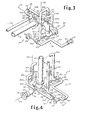
- the loading arm includes a support 10 on which the arms are mounted for rotation.
- Inboard and outboard arms 11 and 12, respectively, provide for flow of fluid from the main riser pipe inlet 13 which will normally be connected to a tank battery.
- inboard and outboard auxiliary arms 14 and 15 provide for flow of vapors through the auxiliary riser pipe outlet 16.
- the auxiliary riser pipe 16 will normally be connected to a facility for handling vapors received from a ship's tank.
- the inboard arms are supported on the support 10 for rotation about horizontal and vertical axes.
- Coaxial swivels 8a and 8b provide for rotation about a.vertical axis.
- Coaxial swivels lla and 14a provide for rotation about a horizontal axis.
- the outboard arms 12 and 15 are supported.on the inboard arms for rotation about a common horizontal axis by swivels 12a and 15a.
- a dual swivel assembly indicated generally at 17 which is designed to connect to spaced flanges such as spaced flanges on the loading manifold of a ship.
- the swivel system 17 provides for rotation of the connecting means of each arm such as the flange connector 18 for the fluid line and the flange connector 19 for the vapor line rotatable about three mutually perpendicular axes 21, 22 and 23.
- the outboard arms 12 and 15 may be connected .together in any desired manner as indicated generally at 24.
- Attached to the free ends of the outboard arms'12 and 15 are a first pair of spaced elbows 25 and 26, respectively.
- these elbows are attached to the outboard arms by the usual flange connectors 27 and 28.
- elbows be connected to each other and this may be readily accomplished by the two pipes 29 and 30 welded to the elbows and joined by the flange connector 31.
- a first pair of spaced swivel joints 32 and 33 are provided. These swivel joints provide for rotation about the common axis 21. In the preferred form of this invention the axis 21 will extend horizontally.
- a second pair of elbows Connected to the first pair of swivel joints are a second pair of elbows.
- an elbow 34 Connected to the swivel 32 is an elbow 34 which in the preferred form is a 90° elbow.
- Connected to the swivel 33 is an elbow indicated generally at 35 which includes a U-section 35a, a straight section 35b, a 90° section 35c, a straight section 35d, and 90° bends 35e and 35f to bring the outlet end of the elbow 35 to a position overlying the elbow 34.
- swivel joints 36 and 37 Connected to the elbows 34 and 35 are a second pair of spaced swivel joints 36 and 37, respectively. These two swivel joints provide for rotation about the common axis 22 which, in the preferred form of the invention, is a vertical axis.
- elbows 34 and 35 are connected together, again by the short pipe sections 38 and 39, interconnected by the flange connector 41.
- a third pair of spaced elbows are connected to the second pair of swivel joints. This may be provided by the elbow 42 connected to swivel joint 36 and by the elbow indicated generally at 43 connected to swivel joint 37.
- the elbow 43 includes a U-shaped section 43a, a straight section 43b, and a 90° section 43c.
- swivels 44 and 45 Connected to the third pair of elbows 42 and 43 are a third pair of spaced swivels 44 and 45...
- the swivels 44 and 45 are arranged for rotation about axis 23 which, in the preferred form of the invention, is a horizontal axis.
- a connector is preferably provided between the elbows 42 and 43 and may be provided by the pipe 47 on elbow 43 and the pipe 48 on elbow 42 joined by the flange connector 49.
- a connecting means of any desired form such as the flanged connector 18 or some form of automatic connector such as shown in U. S. Patent 3,586,350 is provided on swivel 44.
- a connecting means indicated generally at 51 is connected to the swivel 45. This includes elbow 5la to which the pipe section 5lb is attached.
- the connector means 51 may include the flange 19 supported by swivel 50. As is well known in the art, this flange may have substituted therefor an automatic connector.
- the connecting means includes a connecting means swivel joint 52 and an angled arm 53 so that the flange connector 19 can rotate about the center of the connector swivel 52 and position the flange 19 at different points relative to the flange 18 on 7 the liquid arm.
- the several elbows be routed and/or counterbalancing means be provided so that a minimum dead load moment occurs about any substantially horizontal axis of swivel rotation.
- the-connector indicated generally at 51 has extending from the 90° section 51a a counterbalance 55 which counterbalances the weight of the vapor system downstream from the 90° section 51a.
- the elbows 35 and 43 are routed in such manner as to counterbalance rotation of the swivel system about the horizontal axis of rotation 21.
- additional counterbalancing weights could also be utilized as, for instance, where heavy automatic connectors are substituted for the flange connectors 15 or 19 . In this instance it might be desirable to provide additional counterweight to offset the weight of such automatic connectors.
- the vapor swivel system is provided with flange connectors 56, 57 and 58 in addition to connector 28. These connectors together with flange connector 27 permit various sections of the system to be removed for repair without removing other sections.
- the loading arm will function in substantially the same manner as a single fluid loading arm.
- the arm may be rotated about its horizontal and vertical axes on the support and the inboard and outboard arm extended outwardly for attachment to the manifold of a tanker.
- the swivel system With the swivel system in the vicinity of a tanker manifold, the swivel system may be rotated about either of its horizontal axes or its vertical axis to align the connectors with the ship's manifold.
- the vapor connector may be rotated about the vapor connector swivel 52 to accommodate varying distances between the liquid and vapor flanges on the ship's manifold.
- the swivel assembly will accommodate movement of the ship. If, for instance, the fore and aft level of the ship changes the swivel system is free to rotate about axis 23 to accommodate such movement.
- the loading arm may, of course, rise and fall in the conventional manner with movement of tides and rotation of the loading arm swivel system about its three axes, together with movement of the inboard and outboard arms about their axes, will accommodate any movement of the ship.
Landscapes
- Engineering & Computer Science (AREA)
- Mechanical Engineering (AREA)
- Loading And Unloading Of Fuel Tanks Or Ships (AREA)
- Joints Allowing Movement (AREA)
- Manipulator (AREA)
Applications Claiming Priority (2)
| Application Number | Priority Date | Filing Date | Title |
|---|---|---|---|
| US06/129,240 US4290463A (en) | 1980-03-11 | 1980-03-11 | Loading arm |
| US129240 | 1998-08-05 |
Publications (3)
| Publication Number | Publication Date |
|---|---|
| EP0035832A2 true EP0035832A2 (fr) | 1981-09-16 |
| EP0035832A3 EP0035832A3 (en) | 1982-09-08 |
| EP0035832B1 EP0035832B1 (fr) | 1986-06-25 |
Family
ID=22439052
Family Applications (1)
| Application Number | Title | Priority Date | Filing Date |
|---|---|---|---|
| EP19810300539 Expired EP0035832B1 (fr) | 1980-03-11 | 1981-02-10 | Bras de chargement |
Country Status (5)
| Country | Link |
|---|---|
| US (1) | US4290463A (fr) |
| EP (1) | EP0035832B1 (fr) |
| JP (1) | JPS56142200A (fr) |
| CA (1) | CA1149705A (fr) |
| DE (1) | DE3174862D1 (fr) |
Families Citing this family (13)
| Publication number | Priority date | Publication date | Assignee | Title |
|---|---|---|---|---|
| JPS5728050U (fr) * | 1980-07-25 | 1982-02-13 | ||
| US4411290A (en) * | 1981-06-15 | 1983-10-25 | Chevron Research Company | Bottom loading arm for bulk liquid carriers |
| WO2004099061A1 (fr) * | 2003-05-05 | 2004-11-18 | Single Buoy Moorings Inc. | Systeme de transfert d'hydrocarbures equipe d'un bras de transfert a amortissement |
| KR100712076B1 (ko) * | 2005-06-28 | 2007-05-02 | 박재욱 | 액화가스 이송장치 |
| US8382602B2 (en) | 2007-11-30 | 2013-02-26 | Frederick Rieber | Enclosed slide |
| US7815513B2 (en) * | 2007-11-30 | 2010-10-19 | Frederick Rieber | Enclosed slide |
| DE102010064081A1 (de) | 2010-09-09 | 2012-03-15 | Coperion Gmbh | Stationäre pneumatische Schüttgut-Fördervorrichtung zum Beladen und /oder Entladen eines Schiffs |
| DE102012212916A1 (de) * | 2012-07-24 | 2014-01-30 | Putzmeister Engineering Gmbh | Rundverteiler für Dickstoffe |
| US9505568B1 (en) | 2012-09-14 | 2016-11-29 | Sam Carbis Asset Management, Llc | Loading arm with soft-seal hatch cone assembly for top hatch of transport tank |
| US9731915B1 (en) | 2012-09-14 | 2017-08-15 | Sam Carbis Asset Management, Llc | Loading arm with hatch plate for top hatch of transport tank |
| FR3003855B1 (fr) * | 2013-03-29 | 2016-01-29 | Fmc Technologies Sa | Bras de transfert d'un produit fluide de navire a navire |
| CN104671183B (zh) * | 2014-12-30 | 2017-08-29 | 樊冬红 | 一种槽罐车凝结油加热鹤管 |
| CN107055449B (zh) * | 2014-12-30 | 2019-04-19 | 芜湖市金宇石化设备有限公司 | 一种槽罐车凝结油移动式加热鹤管 |
Family Cites Families (7)
| Publication number | Priority date | Publication date | Assignee | Title |
|---|---|---|---|---|
| NL300225A (fr) * | 1900-01-01 | |||
| US3372715A (en) * | 1963-10-25 | 1968-03-12 | Youngstown Sheet And Tube Co | Bottom loading arm |
| US3753453A (en) * | 1968-09-20 | 1973-08-21 | Dover Corp | Fluid handling apparatus |
| US3590870A (en) * | 1969-11-26 | 1971-07-06 | Youngstown Sheet Ahd Tube Co | Loading arm |
| CA936436A (en) * | 1970-01-09 | 1973-11-06 | A. Upton Keith | Fluid transfer apparatus |
| US3825045A (en) * | 1972-08-22 | 1974-07-23 | Fmc Corp | Fluid delivery and vapor recovery apparatus |
| US3896841A (en) * | 1974-03-21 | 1975-07-29 | Fmc Corp | Constant weight-constant dimension coupling assembly for marine loading arms |
-
1980
- 1980-03-11 US US06/129,240 patent/US4290463A/en not_active Expired - Lifetime
-
1981
- 1981-02-10 DE DE8181300539T patent/DE3174862D1/de not_active Expired
- 1981-02-10 EP EP19810300539 patent/EP0035832B1/fr not_active Expired
- 1981-03-10 CA CA000372651A patent/CA1149705A/fr not_active Expired
- 1981-03-11 JP JP3516181A patent/JPS56142200A/ja active Pending
Also Published As
| Publication number | Publication date |
|---|---|
| EP0035832A3 (en) | 1982-09-08 |
| DE3174862D1 (en) | 1986-07-31 |
| EP0035832B1 (fr) | 1986-06-25 |
| US4290463A (en) | 1981-09-22 |
| JPS56142200A (en) | 1981-11-06 |
| CA1149705A (fr) | 1983-07-12 |
Similar Documents
| Publication | Publication Date | Title |
|---|---|---|
| US4290463A (en) | Loading arm | |
| US3434491A (en) | Fluid transfer apparatus | |
| US4261398A (en) | Deepwater offshore loading apparatus | |
| US9403669B2 (en) | Balanced loading arm without a base for transferring a fluid product | |
| US4411290A (en) | Bottom loading arm for bulk liquid carriers | |
| CN103620287A (zh) | 壳形套筒联接器及其应用 | |
| US3889728A (en) | Marine loading arm for bunkering vessels | |
| US3896841A (en) | Constant weight-constant dimension coupling assembly for marine loading arms | |
| GB1600810A (en) | Marine loading arm | |
| US4099542A (en) | Marine loading arm jumper assembly | |
| JP2002543011A (ja) | 流体移送用関節式装置およびそれを備えた積卸しクレーン | |
| US3620268A (en) | Boom loader | |
| US4066098A (en) | Marine loading and bunkering arrangement | |
| US4252162A (en) | Articulated loading arm attitude control system | |
| US4209192A (en) | Fluid transfer adapter for connecting a single conduit to a plurality of tanker manifolds | |
| CA1142054A (fr) | Bras-support articule pour tube transporteur de fluide | |
| CA1105801A (fr) | Adaptateur de transvasement pour le raccordement d'une canalisation unique aux prises de plusieurs wagons-citernes | |
| US3479065A (en) | Coupling device for fluid conducting conduits | |
| EP0679606A1 (fr) | Bras de chargement | |
| US4318423A (en) | External flowline across a universal joint | |
| US5488980A (en) | Suspension device for an oil transferring pipe or hose | |
| US3587643A (en) | Apparatus for transfer of liquids | |
| CN108224075A (zh) | Lng低温流体装卸臂平衡器 | |
| CN218108738U (zh) | 一种清管发球装置 | |
| EP0536367A1 (fr) | Dispositif de suspension de tuyau ou de conduite souple servant au transfert de produits petroliers. |
Legal Events
| Date | Code | Title | Description |
|---|---|---|---|
| PUAI | Public reference made under article 153(3) epc to a published international application that has entered the european phase |
Free format text: ORIGINAL CODE: 0009012 |
|
| AK | Designated contracting states |
Designated state(s): DE FR GB IT |
|
| PUAL | Search report despatched |
Free format text: ORIGINAL CODE: 0009013 |
|
| RHK1 | Main classification (correction) |
Ipc: B67D 5/70 |
|
| AK | Designated contracting states |
Designated state(s): DE FR GB IT |
|
| 17P | Request for examination filed |
Effective date: 19821214 |
|
| RAP1 | Party data changed (applicant data changed or rights of an application transferred) |
Owner name: LTV ENERGY PRODUCTS COMPANY |
|
| GRAA | (expected) grant |
Free format text: ORIGINAL CODE: 0009210 |
|
| AK | Designated contracting states |
Kind code of ref document: B1 Designated state(s): DE FR GB IT |
|
| ITF | It: translation for a ep patent filed | ||
| REF | Corresponds to: |
Ref document number: 3174862 Country of ref document: DE Date of ref document: 19860731 |
|
| ET | Fr: translation filed | ||
| PG25 | Lapsed in a contracting state [announced via postgrant information from national office to epo] |
Ref country code: GB Effective date: 19870210 |
|
| PLBI | Opposition filed |
Free format text: ORIGINAL CODE: 0009260 |
|
| 26 | Opposition filed |
Opponent name: FMC CORPORATION Effective date: 19870325 |
|
| GBPC | Gb: european patent ceased through non-payment of renewal fee |
Free format text: IN PAT.BUL.5145,PAGE 2482 FOR EP 055832 READ EP 035832 |
|
| REG | Reference to a national code |
Ref country code: FR Ref legal event code: ST |
|
| RDAG | Patent revoked |
Free format text: ORIGINAL CODE: 0009271 |
|
| STAA | Information on the status of an ep patent application or granted ep patent |
Free format text: STATUS: PATENT REVOKED |
|
| 27W | Patent revoked |
Effective date: 19871019 |
|
| GBPR | Gb: patent revoked under art. 102 of the ep convention designating the uk as contracting state | ||
| REG | Reference to a national code |
Ref country code: GB Ref legal event code: 7102 |