EP0035839A2 - Appareil et procédé pour la défibration de matière en pâte - Google Patents
Appareil et procédé pour la défibration de matière en pâte Download PDFInfo
- Publication number
- EP0035839A2 EP0035839A2 EP81300736A EP81300736A EP0035839A2 EP 0035839 A2 EP0035839 A2 EP 0035839A2 EP 81300736 A EP81300736 A EP 81300736A EP 81300736 A EP81300736 A EP 81300736A EP 0035839 A2 EP0035839 A2 EP 0035839A2
- Authority
- EP
- European Patent Office
- Prior art keywords
- stator
- rotor
- bladed
- acquisition
- edge
- Prior art date
- Legal status (The legal status is an assumption and is not a legal conclusion. Google has not performed a legal analysis and makes no representation as to the accuracy of the status listed.)
- Granted
Links
Images


Classifications
-
- D—TEXTILES; PAPER
- D21—PAPER-MAKING; PRODUCTION OF CELLULOSE
- D21B—FIBROUS RAW MATERIALS OR THEIR MECHANICAL TREATMENT
- D21B1/00—Fibrous raw materials or their mechanical treatment
- D21B1/04—Fibrous raw materials or their mechanical treatment by dividing raw materials into small particles, e.g. fibres
- D21B1/12—Fibrous raw materials or their mechanical treatment by dividing raw materials into small particles, e.g. fibres by wet methods, by the use of steam
- D21B1/30—Defibrating by other means
- D21B1/34—Kneading or mixing; Pulpers
- D21B1/345—Pulpers
- D21B1/347—Rotor assemblies
Definitions
- the method operates successfully but subjects the rotor and stator to wear at a rapid rate.
- the rotor and stator can be made of wear resistant materials at increased cost, but economic factors make it desirable to find another solution to the problem.
- stator in an annular pattern of generally triangular segments, the segments forming alternate peaks and valleys and either being juxtaposed, or integral as a one piece ring, in a saw tooth or serrated, design.
- the triangular segments may be equally spaced apart with a dwell space between adjacent segments if agitation is not of prime importance.
- Each segment is preferably isosceles triangular in plan and projects inwardly from the periphery of the stator towards the centre of the rotor, the apex edges of the segments outlining an interrupted ring which forms the stock inlet opening of the truncated conical interface of the rotor and stator blades.
- Each peak of each segment has a forward, or "acquisition, edge” separated by an “acquisition space”, or “valley” from the rearward edge of the adjacent segment and forming a predetermined angle of intersection with the rotor blades which produces a “scissors effect”.
- the interior angle at the apex, or peak of each generally triangular segment is preferably obtuse, as is the exterior angle of the acquisition space or valley between the peaks of adjacent segments and there may be as many segments as desired, depending on the agitation, circulation, and degree of breakdown of the material required by the stock charged into the pulper container.
- Clearance at the truncated conical interface normally ranges from 0.25 mm to 0.38 mm.
- the vortical circulation pulper 20 of the invention includes a stock container 21 having a bottom wall 22 and an upstanding side wall 23, there being an opening 24 at the top for receiving the charge 25 of the material to be pulped.
- the charge 25 of material to be pulped is of stock difficult to, or impossible to, defibre in a conventional pulper with conventional clearance,thrust and power for example hemp, flax, rags, used mailbags, leather straps, heavy latex impregnated shoe board, raw cotton and the like.
- a conventional pulper with conventional clearance,thrust and power for example hemp, flax, rags, used mailbags, leather straps, heavy latex impregnated shoe board, raw cotton and the like.
- annular stator 26 of unique design is mounted, preferably in the side wall 23 of container 21, with a circular rotor 27, also of unique design rotatable within the stator and fast on a rotor shaft 28.
- Shaft 28 is cantilever supported in two spaced apart bearings 29 and 31 and driven by a wharve 32, or some other suitable power source well known in the art.
- the stator 26 has a truncated conical, bladed and channeled attrition under-face 33
- the rotor 27 has a truncated conical, bladed and channeled, attrition outer face 34, the faces 33 and 34 jointly forming a truncated conical attrition interface 35 with a small end 36, facing toward, and opening.:into, the interior 37 of the container 21 and forming the stock inlet 38.
- the large end 39 of the interface 35 faces away from the interior of the container and discharge difibred stock into the annular chamber 41.
- Defibred stock may be conducted through conduit 42 and valves 81 and 82 back into container 21 for recirculation and treatment or may be conducted through conduit 83 to further processing.
- Valve 81 may also be used for partial closing of discharge conduit 42 to create back pressure at the interface 35 if desired.
- the shaft 28, rotor 27 and bearings 29 and 31 are movable axially as a unit by the handwheel 43 and gear and rack mechanism 44 to advance and retract the truncated conical rotor outer face 34 relative to the truncated conical under face 33 of the stator to vary clearance.
- the clearance at interface 35 is about 0.13 mm to 0.25 mm so that undue wear is avoided.
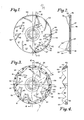
- the rotor 27 of the invention is provided with alternate attrition blades 45 and channels 46, the blades being angled to a radial line such as shown at 47 at an angle which is preferably about 35 0 .
- the rotor 27 is also provided with a plurality of symmetrically arranged vortical circulation vanes such as 48, each upstanding from the disc, or plate-like circular body 49 of the rotor and each having the inner gradually inclined portion 51, preferably angularly bent at 52 for accomplishing vortical circulation.
- Each vortical circulation vane 48 also includes an outer bladed edge 53, the edges 53 of all of the vanes 48 jointly outlining a truncated conical, bladed, outer face 54 for use in reducing large chunks of the difficult to defibre stock as they are moved unidirectionally, usually clockwise in a circular path designated by the hollow headed arrows, by the vortical circulation portions 51 of vanes 48.
- the outer bladed edges 53 are not only sharply inclined at the preferred slope of about 60° from the plane of the body 49 of rotor 27, at the truncated conical interface 35, but they are also angled, in plan, in a preferred range of between thirty to forty degrees from a radial line such as 47, the preferred angle of each bladed edge 53, from its tip 55 to its high point 56, relative to radius 47, being about 35°.
- the spaces between vortical circulation vanes 48 are each designated 57 and the nose cone is designated 58.
- each stator segment exhibits an angle substantially 50° to the axial plane in the interfacial surface.
- the angle of intersection is 35°.
- the stator 26 is shaped in an annular, symmetrical pattern of alternate, generally triangular peaks 59 and valleys 61, the generally triangular peaks 59 being formed in a one-piece ring, or constituting individual segments, for ease of replacement.
- each peak 59 and valley 61 of isosceles triangle configuration in plan with the interior angle 62 at the apex and the exterior angle 63 F t the bottom of each valley being obtuse.
- each peak, or triangular segment 59 is unique in that it is not flat against the body 49 of rotor 27, but instead is inclined to form a portion of a truncated cone, with an outer face 64 and a truncated conical underface 65 having alternate attrition blades 67 and channels 66 running generally radially in the direction of radial line 47 on rotor 27.
- the outer peripheral edge 68 is normal to the plane of the body 49 of rotor 26, but curved to conform to the annular configuration of the stator 26.
- Each stator peak, or triangular segment 59 includes an acquisition, or forward, edge 69 facing towards the direction of travel of chunks being circulated by the vanes 48 of the unidirectionally rotating rotor 27, that direction preferably being clockwise angularly as shown by the hollow headed arrows.
- Each valley 61 in advance of each acquisition edge 69 forms an "acquisition space" for receiving large chunks of difficult to defibre stock-so that such chunks are reduced in size by the successive scissors-like reduction impacts, rips, or tears of the outer bladed edges 53 of the vanes 48 with the acquisition edges 69 of the peaks 59 of.the stator 26.
- the large chunks have been sufficiently reduced in size to permit the fibres therein'to enter the attrition interface 35 they are further defibred therein and discharged from the large end 39 for further processing or recirculation.
- the attrition interface 35 which is bladed and channeled for defibering is in rear of the stock reduction interface 71, both being truncated conical.
- the rearward edge 72 of each peak and the forward or acquisition edge 69 of each peak are slightly curved because formed by a flat plane intersecting a conical surface.
- the angle of each acquisition edge of each peak, to a radial line such as 47 passing through the bottom of the adjacent valley 61, is in the range of about 50° to 70° and preferably about 60°, when viewed in plan as in Fig. 3.
- the acquisition angle 73 which provides the preferred scissors-like reduction effect occurs when the bladed edges 53 of each rotor vane are angularly disposed to a radial line 47 at about 35 0 , and the acquisition edges 69 of each peak 59 are angularly disposed to the same radial line 47 at about 60 0 so that the acquisition angle 73 is about 25° (Fig. 6).
- the acquisition angle remains about the same regardless of whether six to nine segments, or peaks are provided with six to nine vanes, or whether twenty or more peaks and valleys are provided.
- the number of peaks is a function of (1) rotor/stator diameter, and (2) material to be treated.
- a 91.4 cm diameter unit would have nine segments and a similar number of vanes, with easier material, a 91.4 cm diameter unit would have eighteen to twenty segments and nine vanes, or slightly more if desired.
- the rotor/stator combination is required to perform four different functions: (1) agitation; (2) size reduction; (3) defibering;(4) circulation.
- Optimum energy utilisation requires optimising each of these factors in each situation; i.e. enough, but not too much. If, for example, agitation is excessive, energy is wasted; if defibering is inefficient, productivity is reduced; etc. Proper "balance" is thus implied.
- Fig. 8 and Fig. 9 provides different actions, rates of recirculation, agitation, etc.
- the variation of Fig. 8 increases recirculation rate as well as rate of defibering and would be suitable in those situations where (1) the material is already in small pieces (thus coarse reduction is unnecessary) and (2) agitation is not a problem.
- the variation of Fig. 9 further increases recirculation rate and would be suitable in those situations where (1) the material is fibrous (e.g. cotton) and (2) minimum agitation is sufficient.
- annular bladed stator 63 of Fig. 8 has nine peaks 74 of isosceles triangle outline in plan but the interior angle 62 at the apex is obtuse and the triangular peaks 74 are shallow to project only slightly over the rotor blades.
- a dwell portion 75 is provided between each adjacent pair of peaks 74 to decrease agitation, and increase recirculation rate because the material is already in small pieces.
- annular bladed stator 76 has eighteen identical peaks such as 77, juxtaposed with no dwell therebetween so that the stock inlet opening 78 thereof is defined by a multiplicity of acquisiton edges 79.
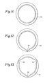
- Figs. 11, 12 and 13 illustrate additional designs are shown in Figs. 11, 12 and 13.
- Fig. 11 illustrates that a stator such as at 85 can be a solid, unbroken ring, if the material of the stock is already in finely divided form. With large pieces of fibrous material such as a design would become blocked. It will work with cotton linters without blocking.
- Fig. 12 illustrates a stator 86 with only one valley 87, or acquisition space, which would be suitable for some intermediate material and provides one escape route to avoid the possibility of blocking.
- the stator of Figs. 11 and 12 would be suitable only in those instances where agitation per se is not a problem.
- Stator 87 has three equally spaced valleys 88, 89 and 91 which provide increased acquisition opportunity and increased agitation.
- the nose cone 58 may be of an area at the base and of a height to nearly occupy the entire stock inlet opening or may be only large enough to guide stock coming in the axis of the rotor outwardly towards the periphery of the rotor.
- the annular, bladed, and channeled stator is so shaped that a series of acquisition edges 69 is created which, in combination with the bladed edges 53 of the rotor vanes 48, form a scissors-like action to rip, cut, shred fibrous material and the like to a completely defibred condition.
- uncooked rags for example, in very large pieces can be quickly and efficiently reduced to homogeneous papermaking stock.
- Rapid rotor/stator wear is avoided by (A) operating at distinct clearance and (B) ensuring that the entire interfacial area is.properly "lubricated” with fibre to prevent metal/metal contact. This is further ensured by providing multiple ramps, acquisition edges, or at critical angle to ensure balanced load.
- the unit is operated with back pressure in a refining chamber (by restricting the valves 43 or 44 in the recirculation line so as to overcome cavitation effects and thus enable complete utilisation of rotor/stator edges.
Landscapes
- Engineering & Computer Science (AREA)
- Life Sciences & Earth Sciences (AREA)
- Wood Science & Technology (AREA)
- Mechanical Engineering (AREA)
- Paper (AREA)
- Crushing And Pulverization Processes (AREA)
- Agricultural Chemicals And Associated Chemicals (AREA)
- Glass Compositions (AREA)
- Preparation Of Compounds By Using Micro-Organisms (AREA)
- Preliminary Treatment Of Fibers (AREA)
- Saccharide Compounds (AREA)
- Medicines Containing Material From Animals Or Micro-Organisms (AREA)
- Grinding Of Cylindrical And Plane Surfaces (AREA)
- Organic Low-Molecular-Weight Compounds And Preparation Thereof (AREA)
- Mixers Of The Rotary Stirring Type (AREA)
Priority Applications (1)
| Application Number | Priority Date | Filing Date | Title |
|---|---|---|---|
| AT81300736T ATE20919T1 (de) | 1980-03-06 | 1981-02-23 | Vorrichtung und verfahren zum mahlen von stoffaufschwemmungen. |
Applications Claiming Priority (2)
| Application Number | Priority Date | Filing Date | Title |
|---|---|---|---|
| US06/127,873 US4365761A (en) | 1980-03-06 | 1980-03-06 | Apparatus and method for defibering unconventional material |
| US127873 | 1980-03-06 |
Publications (3)
| Publication Number | Publication Date |
|---|---|
| EP0035839A2 true EP0035839A2 (fr) | 1981-09-16 |
| EP0035839A3 EP0035839A3 (en) | 1982-04-21 |
| EP0035839B1 EP0035839B1 (fr) | 1986-07-23 |
Family
ID=22432404
Family Applications (1)
| Application Number | Title | Priority Date | Filing Date |
|---|---|---|---|
| EP81300736A Expired EP0035839B1 (fr) | 1980-03-06 | 1981-02-23 | Appareil et procédé pour la défibration de matière en pâte |
Country Status (10)
| Country | Link |
|---|---|
| US (1) | US4365761A (fr) |
| EP (1) | EP0035839B1 (fr) |
| JP (1) | JPS56140118A (fr) |
| AT (1) | ATE20919T1 (fr) |
| AU (1) | AU535692B2 (fr) |
| BR (1) | BR8101329A (fr) |
| CA (1) | CA1159294A (fr) |
| DE (1) | DE3174957D1 (fr) |
| FI (1) | FI74495C (fr) |
| MX (1) | MX152102A (fr) |
Cited By (3)
| Publication number | Priority date | Publication date | Assignee | Title |
|---|---|---|---|---|
| AU683635B2 (en) * | 1992-12-17 | 1997-11-20 | Colorado State University Research Foundation | Treatment method for lignocellulosic biomass |
| WO2008003283A2 (fr) | 2006-07-07 | 2008-01-10 | Gw Fasertechnik Gmbh | Dispositif de fabrication ou de préparation de pâte à papier |
| CN108660548A (zh) * | 2018-04-18 | 2018-10-16 | 海宁市丁桥镇永畅知识产权服务部 | 一种真皮纤维的制备工艺 |
Families Citing this family (13)
| Publication number | Priority date | Publication date | Assignee | Title |
|---|---|---|---|---|
| US5011091A (en) * | 1989-08-10 | 1991-04-30 | Haybuster Manufacturing Inc. | Cellulose fiberization apparatus |
| US5421276A (en) * | 1992-12-15 | 1995-06-06 | Hooper, Jr.; William C. | Method of disposing of absorbent material impregnated with waste |
| US5577674A (en) * | 1993-09-08 | 1996-11-26 | Somat Corporation | Waste pulping and liquid extraction system and method including automatic bag feeding |
| US5451004A (en) * | 1993-09-08 | 1995-09-19 | Somat Corporation | Integrated waste pulping and liquid extraction system |
| US6053441A (en) * | 1997-09-04 | 2000-04-25 | Bolton-Emerson Americas, Inc. | Toroidal flow pulper for difficult materials |
| US7201825B2 (en) * | 2002-10-25 | 2007-04-10 | Weyerhaeuser Company | Process for making a flowable and meterable densified fiber particle |
| US20040081828A1 (en) * | 2002-10-25 | 2004-04-29 | Dezutter Ramon C. | Flowable and meterable densified fiber particle |
| US7364642B2 (en) * | 2003-08-18 | 2008-04-29 | Kimberly-Clark Worldwide, Inc. | Recycling of latex-containing broke |
| WO2007014161A2 (fr) * | 2005-07-22 | 2007-02-01 | Sustainable Solutions, Inc. | Particules de fibres de coton et leur methode de fabrication |
| JP4906593B2 (ja) * | 2007-05-23 | 2012-03-28 | ボイス パテント ゲーエムベーハー | 古紙裁断用ロータのスクリーンプレート |
| CN104452384B (zh) * | 2014-10-22 | 2016-08-17 | 保定钞票纸业有限公司 | 一种用于纤维碎解的转子刀和用于纤维碎解的设备 |
| WO2018222142A1 (fr) * | 2017-05-29 | 2018-12-06 | Aquafilslo D.O.O. | Procédé et dispositif de séparation et de récupération de constituants de tapis à jeter |
| US12571161B2 (en) | 2023-05-24 | 2026-03-10 | Kadant Black Clawson Llc | Deflaking element for pulper |
Family Cites Families (8)
| Publication number | Priority date | Publication date | Assignee | Title |
|---|---|---|---|---|
| US2596586A (en) * | 1947-06-19 | 1952-05-13 | Morden Machines Company | Machine for treating fibrous material |
| GB652439A (en) * | 1947-06-19 | 1951-04-25 | Charles Whitney Morden | Machine for treatment of paper pulp and pulp making materials |
| GB861695A (en) * | 1958-09-02 | 1961-02-22 | Morden Machines Company | Improved rotor cooperating with stationary ring in a machine for shredding and treating fibrous material |
| AT249491B (de) * | 1959-09-19 | 1966-09-26 | P J Wolff & Soehne G M B H App | Maschine zum Aufschließen von Faserstoffen |
| US3428261A (en) * | 1965-10-06 | 1969-02-18 | Bolton Emerson | Method and apparatus for pulping and defibering |
| GB1176412A (en) * | 1967-01-26 | 1970-01-01 | Bolton Emerson | Improvements in and relating to an apparatus and method for Pulping and Defibering |
| US3946951A (en) * | 1974-06-21 | 1976-03-30 | Bolton-Emerson, Inc. | Attrition pulper having high level thrust for grinding pulp and refining fibres |
| CH613484A5 (fr) * | 1976-11-16 | 1979-09-28 | Escher Wyss Gmbh |
-
1980
- 1980-03-06 US US06/127,873 patent/US4365761A/en not_active Expired - Lifetime
-
1981
- 1981-02-05 CA CA000370139A patent/CA1159294A/fr not_active Expired
- 1981-02-23 EP EP81300736A patent/EP0035839B1/fr not_active Expired
- 1981-02-23 AT AT81300736T patent/ATE20919T1/de not_active IP Right Cessation
- 1981-02-23 DE DE8181300736T patent/DE3174957D1/de not_active Expired
- 1981-02-27 AU AU67923/81A patent/AU535692B2/en not_active Ceased
- 1981-03-05 MX MX186241A patent/MX152102A/es unknown
- 1981-03-06 BR BR8101329A patent/BR8101329A/pt unknown
- 1981-03-06 JP JP3235581A patent/JPS56140118A/ja active Granted
- 1981-03-06 FI FI810709A patent/FI74495C/fi not_active IP Right Cessation
Cited By (4)
| Publication number | Priority date | Publication date | Assignee | Title |
|---|---|---|---|---|
| AU683635B2 (en) * | 1992-12-17 | 1997-11-20 | Colorado State University Research Foundation | Treatment method for lignocellulosic biomass |
| WO2008003283A2 (fr) | 2006-07-07 | 2008-01-10 | Gw Fasertechnik Gmbh | Dispositif de fabrication ou de préparation de pâte à papier |
| WO2008003283A3 (fr) * | 2006-07-07 | 2008-03-06 | Gw Fasertechnik Gmbh | Dispositif de fabrication ou de préparation de pâte à papier |
| CN108660548A (zh) * | 2018-04-18 | 2018-10-16 | 海宁市丁桥镇永畅知识产权服务部 | 一种真皮纤维的制备工艺 |
Also Published As
| Publication number | Publication date |
|---|---|
| JPH0320486B2 (fr) | 1991-03-19 |
| DE3174957D1 (en) | 1986-08-28 |
| FI810709L (fi) | 1981-09-07 |
| ATE20919T1 (de) | 1986-08-15 |
| MX152102A (es) | 1985-05-29 |
| FI74495B (fi) | 1987-10-30 |
| BR8101329A (pt) | 1981-09-08 |
| US4365761A (en) | 1982-12-28 |
| FI74495C (fi) | 1988-02-08 |
| AU6792381A (en) | 1981-09-10 |
| CA1159294A (fr) | 1983-12-27 |
| JPS56140118A (en) | 1981-11-02 |
| EP0035839B1 (fr) | 1986-07-23 |
| EP0035839A3 (en) | 1982-04-21 |
| AU535692B2 (en) | 1984-03-29 |
Similar Documents
| Publication | Publication Date | Title |
|---|---|---|
| EP0035839B1 (fr) | Appareil et procédé pour la défibration de matière en pâte | |
| US4480796A (en) | Pulping apparatus including improved rotor | |
| US4109872A (en) | Pulping apparatus for liquid slurry stock | |
| US3894695A (en) | Disintegrator | |
| US3889885A (en) | Pulping apparatus | |
| US6024308A (en) | Conically tapered disc-shaped comminution element for a disc refiner | |
| WO1999054046A1 (fr) | Segment de disque raffineur | |
| US4754935A (en) | Method and apparatus for refining fibrous material | |
| US4401280A (en) | Disc-type pulp refining apparatus | |
| US3946951A (en) | Attrition pulper having high level thrust for grinding pulp and refining fibres | |
| US3960332A (en) | Defibering apparatus for paper making stock | |
| US4382559A (en) | Defibrator | |
| US6053441A (en) | Toroidal flow pulper for difficult materials | |
| WO1994001218A9 (fr) | Pompe de broyage | |
| WO1994001218A1 (fr) | Pompe de broyage | |
| US2681598A (en) | Paper machinery | |
| US4482095A (en) | Bi-directional rotor and stator in a vortical circulation pulper | |
| WO2000006302A1 (fr) | Disque de raffineur comprenant un passage pour la sortie de vapeur | |
| US4283286A (en) | Centrifuge with product accelerator | |
| US2694344A (en) | Paper machinery | |
| CA2276597C (fr) | Element d'alimentation pour matiere fibreuse | |
| US3214104A (en) | Paper making apparatus | |
| US5323914A (en) | Method of and apparatus for separating heavy impurities from fiber suspensions in connection with pumping | |
| WO2000011264A1 (fr) | Plaque de raffineur a chicanes | |
| US5520506A (en) | Pulp slurry-handling, centrifugal pump |
Legal Events
| Date | Code | Title | Description |
|---|---|---|---|
| PUAI | Public reference made under article 153(3) epc to a published international application that has entered the european phase |
Free format text: ORIGINAL CODE: 0009012 |
|
| AK | Designated contracting states |
Designated state(s): AT BE CH DE FR GB IT NL SE |
|
| 17P | Request for examination filed |
Effective date: 19811029 |
|
| PUAL | Search report despatched |
Free format text: ORIGINAL CODE: 0009013 |
|
| AK | Designated contracting states |
Designated state(s): AT BE CH DE FR GB IT NL SE |
|
| GRAA | (expected) grant |
Free format text: ORIGINAL CODE: 0009210 |
|
| AK | Designated contracting states |
Kind code of ref document: B1 Designated state(s): AT BE CH DE FR GB IT LI NL SE |
|
| REF | Corresponds to: |
Ref document number: 20919 Country of ref document: AT Date of ref document: 19860815 Kind code of ref document: T |
|
| ITF | It: translation for a ep patent filed | ||
| REF | Corresponds to: |
Ref document number: 3174957 Country of ref document: DE Date of ref document: 19860828 |
|
| ET | Fr: translation filed | ||
| PLBE | No opposition filed within time limit |
Free format text: ORIGINAL CODE: 0009261 |
|
| STAA | Information on the status of an ep patent application or granted ep patent |
Free format text: STATUS: NO OPPOSITION FILED WITHIN TIME LIMIT |
|
| 26N | No opposition filed | ||
| ITPR | It: changes in ownership of a european patent |
Owner name: CESSIONE;BEMATEC S.A. |
|
| REG | Reference to a national code |
Ref country code: CH Ref legal event code: PUE Owner name: BEMATEC S.A. |
|
| NLS | Nl: assignments of ep-patents |
Owner name: BEMATEC S.A. TE LAUSANNE, ZWITSERLAND. |
|
| REG | Reference to a national code |
Ref country code: GB Ref legal event code: 732 |
|
| REG | Reference to a national code |
Ref country code: FR Ref legal event code: TP |
|
| ITTA | It: last paid annual fee | ||
| EAL | Se: european patent in force in sweden |
Ref document number: 81300736.6 |
|
| PGFP | Annual fee paid to national office [announced via postgrant information from national office to epo] |
Ref country code: BE Payment date: 19971209 Year of fee payment: 18 |
|
| PGFP | Annual fee paid to national office [announced via postgrant information from national office to epo] |
Ref country code: AT Payment date: 19980224 Year of fee payment: 18 |
|
| PGFP | Annual fee paid to national office [announced via postgrant information from national office to epo] |
Ref country code: NL Payment date: 19980228 Year of fee payment: 18 |
|
| PGFP | Annual fee paid to national office [announced via postgrant information from national office to epo] |
Ref country code: CH Payment date: 19980303 Year of fee payment: 18 |
|
| PGFP | Annual fee paid to national office [announced via postgrant information from national office to epo] |
Ref country code: GB Payment date: 19990122 Year of fee payment: 19 |
|
| PGFP | Annual fee paid to national office [announced via postgrant information from national office to epo] |
Ref country code: SE Payment date: 19990125 Year of fee payment: 19 |
|
| PGFP | Annual fee paid to national office [announced via postgrant information from national office to epo] |
Ref country code: FR Payment date: 19990128 Year of fee payment: 19 |
|
| PG25 | Lapsed in a contracting state [announced via postgrant information from national office to epo] |
Ref country code: AT Free format text: LAPSE BECAUSE OF NON-PAYMENT OF DUE FEES Effective date: 19990223 |
|
| PG25 | Lapsed in a contracting state [announced via postgrant information from national office to epo] |
Ref country code: LI Free format text: LAPSE BECAUSE OF NON-PAYMENT OF DUE FEES Effective date: 19990228 Ref country code: CH Free format text: LAPSE BECAUSE OF NON-PAYMENT OF DUE FEES Effective date: 19990228 Ref country code: BE Free format text: LAPSE BECAUSE OF NON-PAYMENT OF DUE FEES Effective date: 19990228 |
|
| PGFP | Annual fee paid to national office [announced via postgrant information from national office to epo] |
Ref country code: DE Payment date: 19990315 Year of fee payment: 19 |
|
| BERE | Be: lapsed |
Owner name: S.A. BEMATEC Effective date: 19990228 |
|
| PG25 | Lapsed in a contracting state [announced via postgrant information from national office to epo] |
Ref country code: NL Free format text: LAPSE BECAUSE OF NON-PAYMENT OF DUE FEES Effective date: 19990901 |
|
| REG | Reference to a national code |
Ref country code: CH Ref legal event code: PL |
|
| PG25 | Lapsed in a contracting state [announced via postgrant information from national office to epo] |
Ref country code: GB Free format text: LAPSE BECAUSE OF NON-PAYMENT OF DUE FEES Effective date: 20000223 |
|
| PG25 | Lapsed in a contracting state [announced via postgrant information from national office to epo] |
Ref country code: SE Free format text: LAPSE BECAUSE OF NON-PAYMENT OF DUE FEES Effective date: 20000224 |
|
| EUG | Se: european patent has lapsed |
Ref document number: 81300736.6 |
|
| GBPC | Gb: european patent ceased through non-payment of renewal fee |
Effective date: 20000223 |
|
| PG25 | Lapsed in a contracting state [announced via postgrant information from national office to epo] |
Ref country code: FR Free format text: LAPSE BECAUSE OF NON-PAYMENT OF DUE FEES Effective date: 20001031 |
|
| PG25 | Lapsed in a contracting state [announced via postgrant information from national office to epo] |
Ref country code: DE Free format text: LAPSE BECAUSE OF NON-PAYMENT OF DUE FEES Effective date: 20001201 |
|
| REG | Reference to a national code |
Ref country code: FR Ref legal event code: ST |